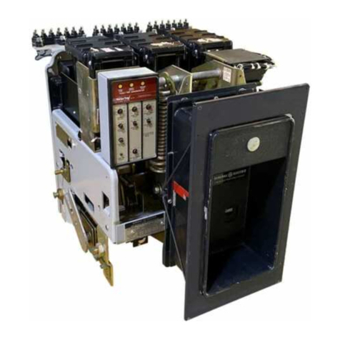
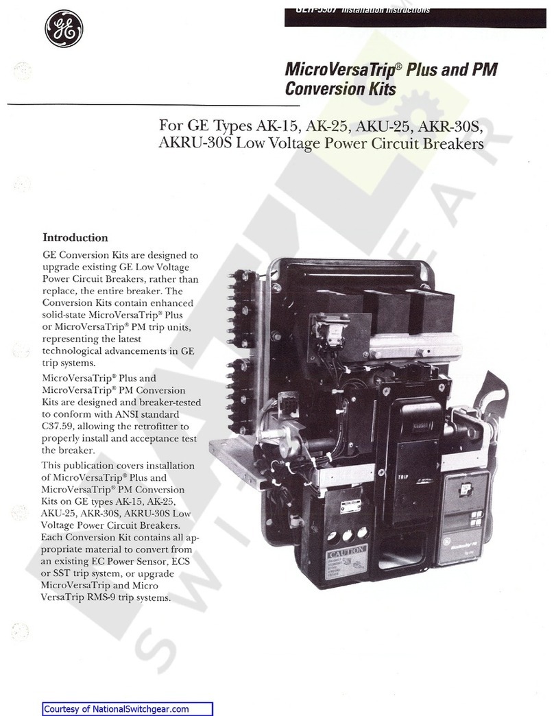
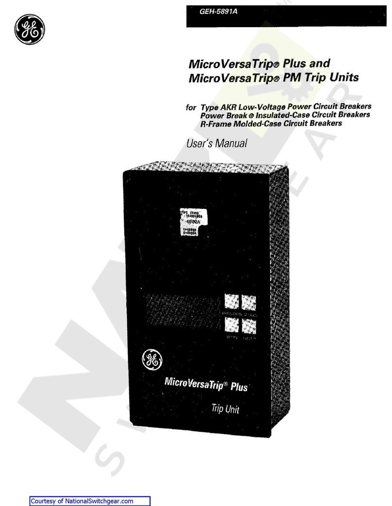
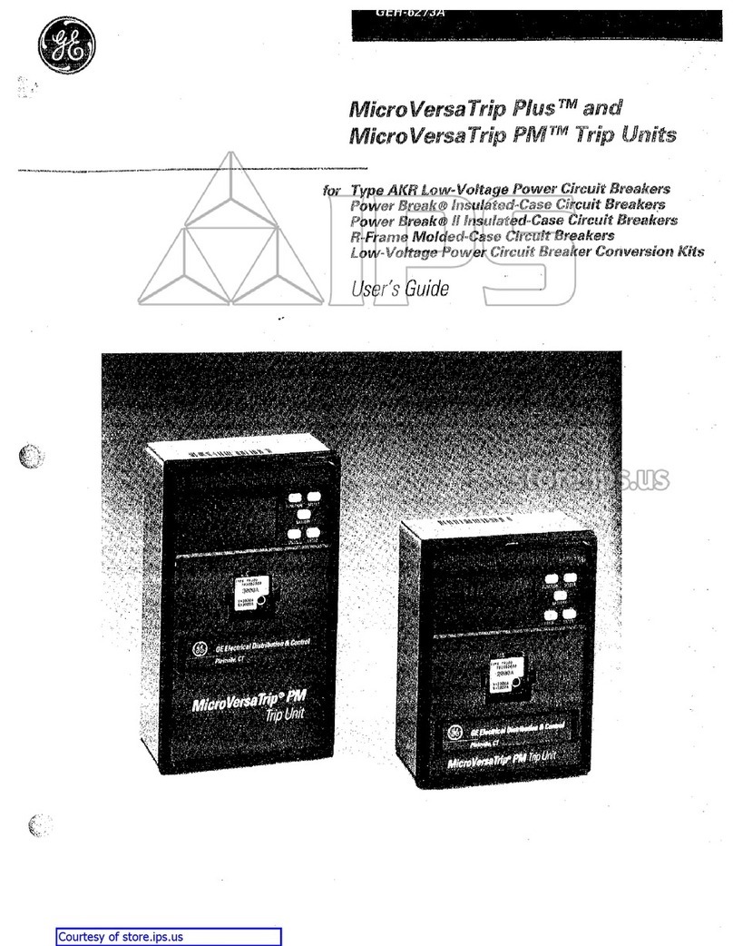
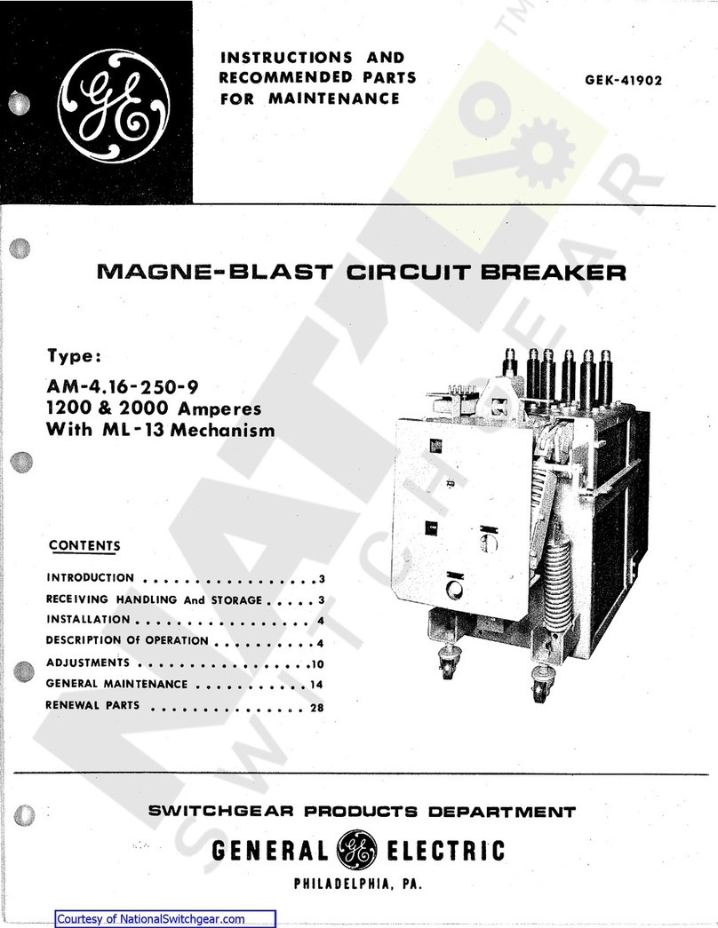
GE MicroVersaTrip Plus User manual

MicroVersaTrip
®
Plus
and
PM
Conversion
Kits
For
I
-
T
-
E
®
Type
KB
Low
-
Voltage
Power
Circuit
Breakers
INTRODUCTION
GE
Conversion
Kits
arc
designed
to
upgrade
existing
I
-
T
-
E
®
Low
Voltage
Power
Circuit
Breakers
,
rather
than
replacing
the
entire
breaker
.
The
Conversion
Kits
contain
enhanced
solid
-
state
MicroVersa
Trip
Plus
or
MicroVersaTrip
-
PM
Trip
Units
,
representing
the
latest
technological
advancement
in
GE
trip
systems
.
MicroVersaTrip
Plus
and
MicroVersaTrip
PM
Conversion
Kits
are
designed
and
breaker
tested
to
conform
with
ANSI
Stan
-
dard
C
37.59
,
allowing
the
retrofittcr
to
properly
install
and
acceptance
test
the
breaker
.
This
publication
covers
installa
-
tion
of
MicroVersaTrip
®
Plus
and
PM
Conversion
Kits
on
I
-
T
-
E
®
Type
KB
Low
Voltage
Power
Cir
-
cuit
Breakers
.
Each
Conversion
Kit
contains
all
the
appropriate
material
to
convert
from
an
existing
I
-
T
-
E
®
electromechanical
trip
system
.
Courtesy of NationalSwitchgear.com

TABLE
OF
CONTENTS
GENERAL
INFORMATION
SECTION
1
3
SECTION
2
PRIOR
TO
INSTALLATION
3
SECTION
3
DISASSEMBLING
THE
BREAKER
Front
and
Back
Frame
Separation
.
.
Metal
Breaker
Frames
Slate
Breaker
Frames
Trip
Paddle
Removal
Old
Trip
Unit
Removal
4
-
9
4
-
7
4
-
5
6
-
7
8
9
SECTION
4
INSTALLING
THE
CONVERSION
KIT
Installing
Phase
Sensors
(
CT
’
s
)
Metal
Breaker
Frames
Slate
Breaker
Frames
Front
/
Back
Frame
Reassembly
(
Metal
Breaker
Frames
)
Front
/
Back
Frame
Reassembly
(
Slate
Breaker
Frames
)
.
Flux
Shifter
/
Programmer
Bracket
Installation
Metal
Breaker
Frames
Slate
Breaker
Frames
Programmer
Wiring
Harness
Communications
Harness
Programmable
Trip
Unit
10
-
23
10
-
12
10
11
-
12
13
14
-
15
16
-
20
16
-
17
18
-
20
21
22
23
SECTION
5
FOUR
-
WIRE
GROUND
FAULT
OPTION
24
TESTING
AND
TROUBLESHOOTING
Cabling
Diagram
25
-
27
SECTION
6
27
2
Courtesy of NationalSwitchgear.com

SECTION
1
GENERAL
INFORMATION
Whenever
the
ground
fault
trip
element
is
fur
-
nished
for
breakers
applied
on
4
-
wire
systems
,
note
that
,
an
associated
neutral
sensor
(
CT
)
is
re
-
quired
for
separate
mounting
in
the
equipment
.
Make
sure
that
retrofitted
breakers
are
applied
within
their
short
circuit
ratings
.
For
example
,
when
the
breaker
’
s
trip
elements
are
to
be
changed
from
long
-
time
instantaneous
to
long
-
time
,
short
-
time
,
the
short
-
time
rating
would
gov
-
ern
the
application
.
As
a
service
-
related
consideration
,
the
installation
of
the
MicroVersaTrip
®
Plus
or
PM
kit
provides
an
excellent
opportunity
to
perform
normal
mainte
-
nance
on
the
breaker
,
particularly
while
the
front
and
back
frames
are
separated
.
Such
procedures
are
described
in
installation
and
maintenance
manuals
normally
supplied
with
breakers
and
equipment
.
Conversion
kit
installation
is
straightforward
.
However
,
careful
workmanship
and
attention
to
these
instructions
should
be
maintained
.
Famil
-
iarity
with
the
breaker
will
prove
helpful
.
The
general
approach
is
to
first
strip
the
breaker
of
its
existing
trip
devices
and
then
install
the
program
-
mable
trip
unit
MicroVersaTrip
®
Plus
or
PM
components
.
Following
this
,
the
converted
breaker
is
performance
-
tested
prior
to
being
restored
to
service
.
The
majority
of
breaker
kit
installations
do
not
re
-
quire
any
customized
assembly
work
.
However
,
some
conversions
may
involve
unusual
mounting
circumstances
or
accessory
'
combinations
which
necessitate
minor
modification
and
or
relocation
of
a
component
(
s
)
.
In
most
instances
,
this
supple
-
mentary
work
can
be
done
on
site
.
Preparatory
to
the
conversion
,
the
installer
should
verify
that
the
correct
kit
,
current
sensors
and
programmable
trip
unit
have
been
furnished
.
SECTION
2
-
PRIOR
TO
INSTALLATION
•
Turn
off
and
lock
out
the
power
source
feed
-
ing
the
breaker
prior
to
attempting
any
installation
,
maintenance
,
or
modification
.
Follow
7
all
lockout
and
tagging
rules
of
the
National
Electrical
Code
and
all
other
appli
-
cable
codes
.
•
Do
not
work
on
a
closed
breaker
or
a
breaker
with
the
closing
springs
charged
.
Trip
OPEN
the
breaker
and
be
sure
the
stored
energy
springs
are
discharged
avoiding
the
possibility
that
the
breakers
may
trip
OPEN
or
the
charg
-
ing
springs
discharge
,
causing
injuries
.
•
For
both
stationary
and
draw
out
breakers
,
trip
OPEN
,
then
remove
the
breaker
to
a
well
lighted
work
area
before
beginning
work
.
•
Do
not
perform
any
maintenance
including
breaker
charging
,
closing
,
tripping
,
or
any
other
function
which
could
cause
significant
movement
of
the
breaker
while
it
is
on
the
draw
out
extension
rails
.
•
Do
not
leave
the
breaker
in
an
intermediate
position
in
the
switchgear
compartment
.
Al
-
ways
leave
it
in
the
CONNECTED
,
TEST
,
or
DISCONNECTED
position
.
Failure
to
do
so
could
lead
to
improper
positioning
of
the
breaker
and
flashback
.
Before
starting
any
work
turn
off
and
lock
out
all
power
sources
leading
to
the
breaker
(
primary
'
and
secondary
)
.
Remove
the
breaker
to
a
clean
,
well
lighted
work
area
.
WARNING
:
Low
7
Voltage
Power
Circuit
Break
-
ers
utilize
high
speed
,
stored
energy
7
spring
operating
mechanisms
.
The
breakers
and
their
enclosures
contain
interlocks
and
safety
features
intended
to
provide
safe
,
proper
op
-
erating
sequences
.
For
maximum
personnel
protection
associated
with
installation
,
opera
-
tion
,
and
maintenance
of
these
breakers
the
following
procedures
must
be
followed
.
Fail
-
ure
to
follow
7
these
procedures
may
result
in
personal
injury
7
or
property
damage
.
•
Only
qualified
persons
,
as
defined
in
the
Na
-
tional
Electrical
Code
,
who
are
familiar
with
the
installation
and
maintenance
of
low
7
volt
-
age
power
circuit
breakers
,
and
switchgear
as
-
semblies
,
should
perform
any
work
associated
with
these
breakers
.
•
Completely
read
and
understand
all
instructions
before
attempting
any
breaker
installation
,
operation
,
maintenance
,
or
modification
.
3
Courtesy of NationalSwitchgear.com

SECTION
3
DISASSEMBLING
THE
BREAKER
RETAINING
STUDS
The
steps
followed
when
converting
a
KB
breaker
are
dependent
on
whether
it
has
a
metal
frame
or
a
slate
frame
.
The
following
sections
include
in
-
structions
for
both
types
.
Before
beginning
the
conversion
,
remove
the
breaker
to
a
clear
,
well
-
lighted
work
bench
.
Make
sure
the
breaker
is
in
the
OPEN
Position
.
SHUNT
SCREW
Front
and
Back
Frame
Separation
METAL
BREAKER
FRAMES
Step
1
.
Remove
the
three
arc
chutes
by
first
removing
the
screw
that
fastens
each
shunt
to
the
contact
arm
,
(
Fig
.
1
)
.
Unscrew
the
(
2
)
retaining
studs
on
the
sides
of
each
arm
chute
and
pull
them
forward
and
up
.
Save
all
the
hardware
.
Step
2
.
Disconnect
the
draw
out
interlock
on
the
right
side
of
the
breaker
.
Remove
the
hairpin
clip
on
the
inside
of
the
pin
and
pull
the
pin
out
.
Save
the
pin
and
clip
(
Fig
.
2
)
Step
3
.
Remove
the
two
outside
pole
line
terminal
hous
-
ings
.
Remove
and
save
the
(
4
)
philip
’
s
head
screws
holding
each
unit
.
(
Fig
3
)
The
housings
can
be
removed
by
pulling
them
up
and
out
.
Some
breakers
may
require
that
the
contact
arm
be
pried
all
the
way
open
using
a
large
screwdriver
.
Step
4
.
Remove
and
save
(
4
)
philip
’
s
head
screws
holding
each
trip
unit
housing
in
the
back
frame
.
(
Fig
.
3
)
.
The
trip
unit
housing
will
be
removed
after
the
frames
are
separated
.
Fig
.
1
.
Arc
Chute
Removal
r
.
Fig
.
2
.
Draw
Out
Interlock
CONTACT
HOUSING
Ml
'
I
a
«
s
;
•
•
»
CONTACT
,
HOUSING
,
SCREWS
a
S
i
X
%
I
I
I
£
£
<
i
>
INSUIATED
HOUSING
SCREWS
©
e
G
.
<
£
v
_
;
.
*
Fig
.
3
.
Insulated
Housing
Removal
4
Courtesy of NationalSwitchgear.com

SECTION
3
DISASSEMBLING
THE
BREAKER
Front
and
Back
Frame
Separation
(
Cont
’
d
)
METAL
BREAKER
FRAMES
FRAME
Step
5
.
Remove
and
save
the
(
2
)
*
/
8
-
16
nuts
at
the
top
side
of
the
breaker
,
holding
the
front
and
back
frames
together
.
The
nuts
can
only
be
accessed
with
the
contact
housings
removed
,
using
a
V
\
6
open
end
wrench
.
(
Fig
.
4
)
Step
6
.
Remove
and
save
the
(
2
)
%
-
16
nuts
at
the
bottom
side
of
the
breaker
,
holding
the
front
and
back
frames
together
(
Fig
.
5
)
.
Use
a
long
extension
and
a
socket
wrench
.
The
frames
should
now
be
gently
separated
,
being
careful
not
to
damage
the
trip
unit
housings
.
Step
7
.
Remove
the
trip
unit
assemblies
from
the
front
frame
.
Remove
and
discard
the
(
2
)
philip
'
s
head
screws
fastening
each
contact
arm
to
the
electro
-
mechanical
trip
units
.
(
Fig
.
6
)
BOLT
Fig
.
4
.
Top
Frame
Bolt
Removal
Fig
.
5
.
Bottom
Frame
Bolt
Removal
CONTACT
AND
SCREWS
TRIP
PADDLE
TRIP
PADDLE
?
SCREWS
Fig
.
6
.
Bottom
Frame
Bolt
Removal
5
Courtesy of NationalSwitchgear.com

SECTION
3
DISASSEMBLING
THE
BREAKER
Front
and
Back
Frame
Separation
SLATE
BREAKER
FRAMES
SHUNT
SCREW
Step
1
.
Remove
the
three
arc
chutes
by
first
removing
the
5
/
i
6
-
18
slotted
screws
that
fasten
each
shunt
to
the
contact
arm
.
(
Fig
.
7
)
Pull
the
arc
chutes
for
-
ward
and
up
.
Save
hardware
to
reuse
when
reassembled
.
Step
2
.
If
the
draw
out
circuit
breaker
is
equipped
with
an
interlock
device
,
disconnect
the
draw
out
in
-
terlock
linkage
on
the
right
side
of
the
breaker
(
Fig
.
8
)
.
Discard
the
trip
bar
link
shown
in
(
Fig
.
9
)
.
Save
the
rest
of
the
linkage
to
be
reused
.
Fig
.
7
.
Arc
Chute
Removal
Fig
.
8
.
Draw
Out
Interlock
Linkage
Fig
.
9
.
Trip
Bar
Link
6
Courtesy of NationalSwitchgear.com

SECTION
3
DISASSEMBLING
THE
BREAKER
I
Front
and
Back
Frame
Separation
(
Cont
’
d
)
I I
V
<
S
>
®
SLATE
BREAKER
FRAMES
e
H
Step
3
.
Remove
the
load
terminal
bracket
on
the
back
side
of
the
breaker
.
(
Fig
.
10
)
.
Remove
and
dis
-
card
the
(
3
)
slotted
screws
that
hold
it
in
place
.
Step
4
.
Remove
the
(
2
)
5
/
16
-
18
x
2
"
slotted
screws
above
each
load
terminal
and
discard
them
.
(
Fig
.
10
)
Step
5
.
Remove
the
1
/
4
-
20
x
1
3
/
4
”
and
10
-
32
x
1
3
/
4
”
slotted
screws
below
each
load
terminal
and
dis
-
card
them
.
(
Fig
.
10
)
Step
6
.
Remove
and
save
the
(
6
)
3
/
8
-
16
x
11
/
2
"
bolts
that
hold
the
front
and
back
frame
together
(
Fig
.
5
)
.
Carefully
separate
the
frames
.
The
electromechanical
trip
units
will
be
fastened
to
the
front
frame
.
Step
7
.
With
the
front
frame
rolled
over
on
the
top
side
,
the
(
2
)
3
/
8
-
16
x
1
1
/
4
”
slotted
screws
in
each
trip
unit
can
be
removed
.
The
screws
hold
the
trip
units
to
the
contact
arm
.
(
Fig
.
12
)
t
.
:
$
i
3
f
.
i
Vie
-
18
SCREWS
$
9
e
^
0
&
*
LOAD
TERMINAL
BRACKET
wy
2
•
m
.
XT
14
-
20
SCREWS
r
*
10
-
32
SCREWS
Fig
.
10
.
Trip
Unit
Screw
Removal
FRAME
BOLTS
CONTACT
ARM
SCREWS
Fig
.
12
.
Trip
Unit
Removal
7
Courtesy of NationalSwitchgear.com

SECTION
3
DISASSEMBLING
THE
BREAKER
Trip
Paddle
Removal
METAL
BREAKER
FRAMES
Step
1
.
Remove
the
(
2
)
screws
holding
each
trip
paddle
to
the
common
trip
bar
(
Fig
.
6
page
5
)
.
Step
2
.
Return
the
(
2
)
screws
on
the
left
end
of
the
trip
bar
that
hold
the
trip
bar
rotation
adjustment
plate
(
Fig
.
13
)
.
ADJUSTMENT
PI
ATE
Fig
.
13
.
Trip
Paddle
Removal
•
:
:
J
V
.
8
Courtesy of NationalSwitchgear.com

SECTION
3
DISASSEMBLING
THE
BREAKER
LOAD
TERMINAL
BRACKET
SCREWS
Removal
of
the
Old
Trip
Units
METAL
BREAKER
FRAMES
Step
1
.
Remove
and
discard
the
(
2
)
load
terminal
bracket
screws
from
the
back
of
each
trip
unit
housing
.
(
Fig
14
)
Step
2
.
Remove
and
discard
the
(
2
or
4
)
trip
unit
screws
from
the
back
of
each
trip
unit
housing
.
(
Fig
.
14
)
Step
3
.
Remove
and
discard
the
(
2
)
load
terminal
screws
on
the
top
of
each
trip
unit
(
Fig
.
15
)
.
Discard
the
electromechanical
trip
units
.
Step
4
.
Separate
the
load
terminal
bracket
from
the
old
load
terminal
(
Fig
.
16
)
.
Discard
the
load
termi
-
nal
and
the
hardware
,
but
save
the
bracket
.
TRIP
UNIT
SCREWS
Fig
.
14
.
Trip
Unit
Disassembly
(
Back
)
1
,
TOP
BUS
SCREWS
rrm
Fig
.
15
.
Trip
Unit
Disassembly
(
Top
)
LOAD
TERMINAL
BRACKET
Fig
.
16
.
Load
Terminal
and
Bracket
9
Courtesy of NationalSwitchgear.com

SECTION
4
INSTALLING
THE
CONVERSION
KIT
%
-
l
6
X
1
"
BOLT
NEW
LOAD
TERMINAL
Installing
Phase
Sensors
(
CT
’
s
)
METAL
BREAKER
FRAMES
h
.
1
'
-
Step
1
.
Mount
the
new
copper
load
terminal
provided
in
the
insulated
housing
.
Use
the
bracket
removed
in
step
4
on
page
9
(
Fig
.
17
)
.
The
bracket
is
in
-
stalled
on
the
bottom
side
of
the
load
terminal
.
Use
the
(
2
)
V
\
-
20
x
VA
"
screws
with
plain
and
lock
washers
,
and
the
Vs
-
lb
x
T
'
bolt
with
a
plain
and
lock
washer
for
each
phase
.
Step
2
.
Assemble
the
”
S
”
shaped
steel
bracket
on
the
front
of
each
housing
placing
a
fiber
barrier
be
-
tween
the
bracket
and
the
new
load
terminal
(
Fig
.
19
)
.
Insert
the
(
2
)
!
4
-
20
x
VA
"
and
lock
washers
provided
,
through
the
holes
above
each
load
terminal
(
Fig
.
18
)
.
Step
3
.
Place
a
spacer
,
phase
sensor
(
CT
)
,
insulated
bar
-
rier
and
top
copper
bus
over
each
CT
post
as
shown
in
sequence
(
Fig
.
19
)
from
left
to
right
.
The
top
copper
bus
is
held
in
place
using
a
%
-
16
x
1
14
bolt
with
a
plain
and
lock
washer
pro
-
vided
.
Also
,
insert
the
(
2
)
14
-
20
x
%
”
screws
with
plain
and
lock
washers
provided
threaded
into
the
"
S
"
bracket
.
'
/
.
-
20
X
1
W
'
SCREWS
E
•
Fig
.
17
.
Load
Terminal
Installation
with
plain
screws
14
-
20
X
1
VH
"
SCREWS
Fig
.
18
.
“
S
”
Bracket
Installation
'
4
-
20
X
VA
''
SCREWS
INSULATED
BARRIER
“
S
”
BRACKET
'
)
\
\
TOP
COPPER
»
BUS
'
FIBER
BARRIER
%
-
l
6
X
VA
"
BOLT
SPACER
Fig
.
19
.
CT
Assembly
10
Courtesy of NationalSwitchgear.com

SECTION
4
INSTALLING
THE
CONVERSION
KIT
TOP
14
-
20
X
VA
"
COPPER
Installing
Phase
Sensors
(
CT
’
s
)
(
Contfd
)
SLATE
BREAKER
FRAMES
Step
1
.
Assemble
the
steel
"
S
"
bracket
to
the
bottom
side
of
the
top
copper
Phase
Sensor
(
CT
)
bus
.
Insert
the
(
2
)
!
/
4
-
20
X
VS
"
bolts
with
plain
and
lock
wash
-
ers
provided
through
the
slots
in
the
copper
bus
(
Fig
.
20
)
.
Tighten
finger
tight
for
now
.
Step
2
.
Assemble
the
spacer
,
CT
and
insulated
barrier
over
the
CT
post
on
the
new
copper
load
terminal
(
Fig
.
21
)
.
Hold
the
CT
in
place
with
the
top
cop
-
per
bus
and
the
%
-
16
x
1
!
4
"
bolt
,
flat
washer
,
and
lock
washer
provided
.
Tighten
the
bolt
finger
tight
for
now
.
Step
3
.
Insert
a
fiber
phase
barrier
between
the
top
cop
-
per
CT
bus
and
the
load
terminal
(
Fig
.
21
)
.
Fig
-
ure
22
shows
the
assembled
CT
'
s
.
BRACKET
Fig
.
20
.
Copper
CT
Bus
Assembly
COPPER
LOAD
TERMINAL
L
*
FIBER
BARRIER
INSULATED
BARRIER
NOTE
:
Occasionally
,
during
current
sensor
manufacturing
,
a
slight
separation
occurs
of
the
epoxy
from
the
plastic
shell
.
This
may
amount
to
as
much
as
0.030
"
and
has
no
effect
on
performance
.
Additionally
,
slight
surface
imperfections
are
part
of
the
epoxy
curing
process
and
have
no
effect
on
performance
.
SPACER
Fig
.
21
.
CT
Assembly
Progression
Fig
.
22
.
CT
Assemblies
11
Courtesy of NationalSwitchgear.com

SECTION
4
INSTALLING
THE
CONVERSION
KIT
Installing
Phase
Sensors
(
CT
’
s
)
(
Cont
'
d
)
SLATE
BREAKER
FRAMES
/
T
>
5
/
l
(
rl
8
X
1
"
BOLTS
Step
4
.
Bolt
each
CT
assembly
to
the
contact
arms
in
the
front
frame
using
the
(
2
)
/
46
-
18
x
1
”
bolts
with
plain
and
lock
washers
provided
per
phase
(
Fig
.
23
)
.
Step
5
.
Tighten
the
contact
arm
bolts
to
100
in
.
lbs
*
(
Fig
.
24
)
*
IMPORTANT
NOTE
:
Steps
designated
by
an
(
*
)
are
critical
electrical
integrity
connec
-
tions
.
They
must
be
correctly
tightened
for
proper
operation
.
Failure
to
tighten
properly
will
cause
a
breaker
failure
resulting
in
prop
-
erty
damage
or
personal
injury
.
Fig
.
23
.
CT
Assembly
Installation
.
i
Fig
.
24
.
Contact
Arm
Bolt
Torque
12
Courtesy of NationalSwitchgear.com

SECTION
4
INSTALLING
THE
CONVERSION
KIT
Front
and
Back
Frame
Reassembly
METAL
BREAKER
FRAMES
Step
1
.
Use
the
(
2
)
Me
-
18
xl
”
bolts
with
plain
and
lock
washers
provided
to
fasten
each
CT
assembly
to
the
contact
arms
on
the
front
frame
(
Fig
.
25
)
.
Tighten
the
bolts
to
100
in
.
lbs
.
*
Step
2
.
Carefully
reassemble
the
front
and
back
frames
.
Use
the
hardware
removed
in
steps
5
and
6
on
page
5
to
hold
the
frames
together
.
Step
3
.
Return
the
two
line
terminal
housings
and
fasten
in
place
with
the
hardware
removed
in
steps
3
and
4
on
page
4
(
Fig
.
26
)
.
Step
4
.
Return
the
draw
out
interlock
lever
removed
in
step
2
on
page
4
.
Step
5
.
Tighten
the
CT
bolts
inserted
in
step
3
on
page
10
to
200
in
.
lbs
.
*
(
Fig
.
27
)
.
Fig
.
25
.
CT
Assembly
Installation
*
IMPORTANT
NOTE
:
Steps
designated
by
an
(
*
)
are
critical
electrical
integrity
connec
-
tions
.
They
must
be
correctly
tightened
for
proper
operation
.
Failure
to
tighten
properly
will
cause
a
breaker
failure
resulting
in
prop
-
erty
damage
or
personal
injury
.
Fig
.
26
.
Frame
Assembly
Fig
.
27
.
CT
Bolt
Torque
13
Courtesy of NationalSwitchgear.com

SECTION
4
INSTALLING
THE
CONVERSION
KIT
Front
and
Back
Frame
Reassembly
SLATE
BREAKER
FRAMES
Step
1
.
Carefully
place
the
front
and
back
frames
to
-
gether
while
guiding
the
new
load
terminals
through
the
holes
in
the
back
frame
(
Fig
.
28
)
.
Make
certain
that
the
fiber
barriers
installed
in
step
3
on
page
11
are
in
proper
position
.
Step
2
.
Return
the
frame
bolts
removed
in
step
6
on
page
7
(
Fig
.
29
)
.
Step
3
.
Insert
the
(
2
)
14
-
20
x
l
7
/
6
"
screws
with
plain
and
lock
washers
provided
through
the
holes
in
the
slate
back
frame
above
the
load
terminals
(
Fig
.
29
)
.
Step
4
.
Reassemble
the
load
terminal
bracket
removed
in
step
3
on
page
9
.
Use
the
(
2
)
14
-
20
x
V
/
H
"
screws
and
the
M
6
-
18
xl
"
bolt
provided
with
plain
and
lock
washers
(
Fig
.
30
)
.
i
.
Fig
.
28
.
Frame
Assembly
FIBER
BARRIER
“
S
”
BRACKET
^
SCREWS
Fig
.
29
.
Frame
Mounting
Hardware
i
i
sac
i
•
A
^
®
lift
{
s
©
o
©
e
SB
m
•
*
•
•
\
•
;
i
L
Fig
.
30
.
Load
Terminal
Brackets
14
Courtesy of NationalSwitchgear.com

SECTION
4
INSTALLING
THE
CONVERSION
KIT
Front
and
Back
Frame
Reassembly
(
Cont
’
d
)
SLATE
BREAKER
FRAMES
Step
5
.
Tighten
the
CT
post
bolts
to
200
in
.
lbs
.
*
(
Fig
.
31
)
.
Step
6
.
Tighten
the
"
S
"
bracket
bolts
inserted
in
step
1
on
page
11
.
*
IMPORTANT
NOTE
:
Steps
designated
by
an
(
*
)
are
critical
electrical
integrity
connec
-
tions
.
They
must
be
correctly
tightened
for
proper
operation
.
Failure
to
tighten
properly
will
cause
a
breaker
failure
resulting
in
prop
-
erty
damage
or
personal
injury
.
Fig
.
31
.
CT
Bolt
Torque
15
Courtesy of NationalSwitchgear.com

SECTION
4
INSTALLING
THE
CONVERSION
KIT
FLUX
SHIFTER
MOUNTING
HOLES
Flux
Shifter
/
Programmer
Bracket
Installation
METAL
BREAKER
FRAMES
Step
1
.
Install
the
new
trip
paddle
on
the
right
end
of
the
common
trip
bar
using
the
(
2
)
8
-
32
x
%
"
screws
with
nuts
and
lock
washers
provided
(
Fig
32
)
.
Step
2
.
Insert
the
(
2
)
10
-
32
x
!
4
"
screws
with
the
captive
lock
washers
into
the
threaded
holes
in
the
right
side
of
the
breaker
frame
(
Fig
.
32
)
.
The
screws
will
hold
the
flux
shifter
/
programmer
bracket
in
place
.
Step
3
.
Install
the
flux
shifter
/
programmer
bracket
over
the
(
2
)
screws
inserted
in
Step
2
above
(
Fig
.
33
)
.
The
bracket
is
inserted
in
and
lifted
into
place
.
Step
4
.
Bolt
the
reset
linkage
pivot
pin
to
the
crossbar
arm
on
the
right
side
of
the
breaker
(
Fig
.
34
)
.
In
-
sert
the
pin
into
the
hole
closest
to
the
cross
bar
pivot
.
Use
the
!
4
-
20
nut
and
lock
washer
provided
.
The
notched
end
of
the
reset
linkage
is
fastened
to
the
pin
using
the
plain
washer
and
cotter
pin
provided
.
TRIP
ADDLE
Fig
.
32
.
Trip
Paddle
Installation
FLUX
SHIFTER
Fig
.
33
.
Flux
Shifter
/
Programmer
Bracket
PIVOT
Fig
.
34
.
Reset
Linkage
Pivot
Pin
16
Courtesy of NationalSwitchgear.com

SECTION
4
INSTALLING
THE
CONVERSION
KIT
Flux
Shifter
/
Programmer
Bracket
Installation
(
Cont
’
d
)
RESET
ARM
METAL
BREAKER
FRAMES
STUD
Step
5
.
Place
the
slot
in
the
opposite
end
of
the
reset
linkage
over
the
bottom
stud
on
the
flux
shifter
reset
arm
.
(
Fig
.
35
)
.
Use
the
nut
and
washer
al
-
ready
assembled
on
the
stud
to
hold
it
in
place
.
Step
6
.
Thread
the
assembly
support
nut
against
the
right
side
of
the
mechanism
until
the
programmer
bracket
is
square
with
the
breaker
frame
(
Fig
.
36
)
.
Lock
the
support
nut
with
the
locking
nut
.
Step
7
.
Once
the
flux
shifter
and
trip
paddle
are
in
-
stalled
,
the
following
adjustment
must
be
made
:
With
the
breaker
in
the
CLOSED
position
,
the
gap
between
the
trip
paddle
adjustment
screw
and
the
trip
slide
of
the
flux
shifter
should
be
Vis
of
an
inch
.
Use
a
Vi
"
wrench
or
nut
driver
to
ad
-
just
the
screw
.
It
may
help
to
gauge
the
air
gap
with
a
VW
'
diameter
rod
or
drill
(
not
provided
)
.
The
best
approach
is
to
adjust
the
breaker
in
the
open
position
,
then
check
it
in
the
closed
position
.
OPTIONAL
TEST
:
The
flux
shifter
assembly
can
be
tested
at
this
point
by
applying
a
9
volt
dc
power
source
to
the
flux
shifter
leads
.
The
red
lead
is
the
positive
.
The
breaker
should
trip
.
Fig
.
35
.
Reset
Link
Installation
SUPPORT
Fig
.
36
.
Flux
Shifter
Adjustment
IMPORTANT
NOTE
:
Extreme
caution
must
be
used
when
working
on
a
closed
breaker
.
DO
NOT
reach
your
hands
into
the
mecha
-
nism
while
adjusting
the
flux
shifter
.
17
Courtesy of NationalSwitchgear.com

SECTION
4
INSTALLING
THE
CONVERSION
KIT
m
Flux
Shifter
/
Programmer
Bracket
Installation
(
Cont
’
d
)
4
*
SLATE
BREAKER
FRAMES
Step
1
.
Install
the
new
trip
paddle
provided
on
the
com
-
mon
trip
bar
on
the
right
end
.
Use
the
10
-
32
x
1
”
screw
,
nut
,
and
lock
washer
to
fasten
the
trip
paddle
(
Fig
.
37
)
.
Step
2
.
Start
the
(
2
)
10
-
32
x
Zi
"
screws
with
captive
lock
washers
into
the
right
side
of
the
frame
(
Fig
.
37
)
.
The
screws
will
hold
the
flux
shifter
assembly
in
place
.
Step
3
.
Install
the
flux
shifter
/
programmer
bracket
as
-
sembly
over
the
two
(
2
)
screws
.
The
assembly
is
held
against
the
frame
and
lifted
up
into
place
(
Fig
.
39
)
.
P
LE
Fig
.
37
.
Trip
Paddle
Installation
Fig
.
38
.
Flux
Shifter
/
Programmer
Bracket
Fig
.
39
.
Flux
Shifter
Assembly
Installed
18
Courtesy of NationalSwitchgear.com

SECTION
4
INSTALLING
THE
CONVERSION
KIT
CROSSBAR
Flux
Shifter
/
Programmer
Bracket
Installation
(
Cont
’
d
)
SLATE
BREAKER
FRAMES
Step
4
.
Place
the
end
of
the
reset
link
with
the
!
4
"
hole
over
the
!
4
”
pin
on
the
end
of
the
cross
bar
(
Fig
.
40
)
.
The
notched
edge
is
up
.
Use
the
plain
washer
and
cotter
pin
provided
to
fasten
the
link
.
Step
5
.
The
slot
in
the
opposite
end
of
the
link
is
placed
over
the
bottom
stud
on
the
flux
shifter
reset
arm
Use
the
nut
and
washer
already
assembled
on
the
stud
to
hold
in
place
(
Fig
.
41
)
.
Step
6
.
Place
the
slotted
draw
out
interlock
link
removed
in
Step
2
on
page
6
over
the
two
posts
on
the
front
and
back
frames
.
Use
the
existing
washers
and
new
cotter
pins
provided
to
fasten
it
.
Step
7
.
Add
the
new
link
shown
in
(
Fig
.
42
)
by
threading
the
!
/
4
-
20
x
Vi
'
screw
through
the
%
"
bushing
pro
-
vided
with
the
link
.
Step
8
.
Bend
the
tang
on
the
trip
paddle
until
the
trip
bar
can
rotate
to
the
fully
reset
position
and
there
is
not
more
than
Vn
"
clearance
between
the
tang
and
the
new
interlock
link
(
Fig
.
42
)
.
Fig
.
40
.
Reset
Link
Installation
RESET
LINK
RESET
ARM
STUD
NEW
LINK
I
Fig
.
41
.
Reset
Arm
Assembly
OLD
LINK
S
'
r
Fig
.
42
.
Interlock
Linkage
19
Courtesy of NationalSwitchgear.com

SECTION
4
INSTALLING
THE
CONVERSION
KIT
Flux
Shifter
/
Programmer
Bracket
Installation
(
Cont
’
d
)
SLATE
BREAKER
FRAMES
Step
9
.
Thread
the
assembly
support
nut
against
the
right
side
of
the
mechanism
until
the
programmer
bracket
is
square
with
the
breaker
frame
(
Fig
.
43
)
.
Lock
the
support
nut
with
the
locking
nut
.
Step
10
.
Once
the
flux
shifter
and
trip
paddle
are
in
-
stalled
,
the
following
adjustment
must
be
made
:
With
the
breaker
in
the
CLOSED
position
,
the
gap
between
the
trip
paddle
adjustment
screw
and
the
trip
slide
of
the
flux
shifter
should
be
]
/
i
6
of
an
inch
.
Use
a
lA
"
wrench
or
nut
driver
to
ad
-
just
the
screw
.
It
may
help
to
gauge
the
air
gap
with
a
V
\
t
>
"
diameter
rod
or
drill
(
not
provided
)
.
The
best
approach
is
to
adjust
the
breaker
in
the
open
position
,
then
check
it
in
the
closed
position
.
OPTIONAL
TEST
:
The
flux
shifter
assembly
can
be
tested
at
this
point
by
applying
a
9
volt
dc
power
source
to
the
flux
shifter
leads
.
The
red
lead
is
the
positive
.
The
breaker
should
trip
.
Fig
.
43
.
Flux
Shifter
Adjustment
IMPORTANT
NOTE
:
Extreme
caution
must
be
used
when
working
on
a
closed
breaker
.
DO
NOT
reach
your
hands
into
the
mecha
-
nism
while
adjusting
the
flux
shifter
.
NOTE
:
The
flux
shifter
assembly
and
the
trip
bar
assembly
should
operate
freely
.
Make
sure
that
the
operation
of
the
trip
slide
on
the
flux
shifter
does
not
interfere
with
the
old
phe
-
nolic
trip
cam
on
slate
back
type
KC
breakers
.
The
trip
slide
should
only
contact
with
the
trip
cam
adjustment
screw
during
normal
op
-
eration
.
File
down
the
phenolic
cam
to
make
clearance
if
needed
.
20
Courtesy of NationalSwitchgear.com
Other manuals for MicroVersaTrip Plus
5
This manual suits for next models
1
Table of contents
Other GE Circuit Breaker manuals