manuals.online logo
Brands
  1. Home
  2. •
  3. Brands
  4. •
  5. GE
  6. •
  7. Circuit Breaker
  8. •
  9. GE EntelliGuard GBKRKR User manual

GE EntelliGuard GBKRKR User manual

1
Introduction
Key Interlock Kit:
The breaker key lock is an optional accessory,
which will keep the breaker in trip free state while
locked. Maximum 4 keys of Ronis/Profalux or Kirk
type can be used. All EntelliGuard Devices can be
equipped with one of the three locks, that when
fitted as indicated allow the use of one to four key
locks that lock the device in its open position.
Figure 1. (A) Front Cover
Devices are found in two Variants:
1. Factory mounted mechanism:
The breaker/device is supplied off works with all
cams and screws allowing the user to mount a
separately acquired GE type lock kit.
2. Field mountable device:
A kit is supplied allowing the field mounting of the
locking mechanism and allowing the use of a lock
of the correct type purchased elsewhere
Catalog Number:
Installation of kit
Use the following procedure to install the Key
Interlock Key accessory into the circuit breaker.
1. Turn the breaker off and discharge the closing
springs by depressing the OFF and ON buttons in
the sequence OFF-ON-OFF. Verify that the
breaker OFF-ON indicator shows OFF and that the
charge indicator shows DISCHARGE. If installing
in a draw-out type breaker remove breaker from
adaptor (cassette) before continuing.
Catalog No
Description
GBKRKR
Kirk Key Interlock kit
GBRONR
Ronis Interlock kit
GBPROR
Profalux Interlock kit
EntelliGuard ®G Circuit Breaker
Accessories
Key Interlock Kit Breaker Mounted
WARNING: Before installing any accessories, turn
the breaker OFF, disconnect it from all voltage
sources, and discharge the closing spings.
AVERTISSEMENT: Avant d’installer tout accessoire,
mettre le disjoncteur en position OFF, le
déconnecter de toute tension d’alimentation , et
décharger les resorts d’armement
DEH-41407 Installation Instructions
2
2. Loosen the 6 screws on front cover (fascia)
using a posidrive screw driver as shown in Fig 1.B
Rotate the charging handle down and slide the
front cover over the handle to remove the front
cover as shown in Fig. 1.C.
Figure 1. (B) Screw Removal (C) Handle Rotation
3. If the locking mechanism device has been
supplied factory fitted, remove the bracket and
cover from the EntelliGuard device. If supplied as
a field mountable kit, please proceed to step 4.
4. Take the Lock cover and carefully break out the
openings needed to place the required number of
locks
5. Fix each lock to the lock bracket using the
fixation nuts as indicated in Fig. 2
Figure 2.
6. Using the nut supplied with each lock fix the
activating CAM. Ensure that the CAM is positioned
as indicated in fig. 3. For Kirk Lock, insert the
spacer and fix the cam supplied with the Kit using
the screws provided in the lock.
Ronis lock
Profalux lock
Kirk lock
Figure 3.
7. Using the supplied screws fit the cover onto the
mechanism.
Spacer
3
8. Uninstall the Motor operator (Optional if
present), Grounding nut & Nylock nut as shown.
Fig 4.
Grounding nut Nylock nut
Figure 4.
9. Install adaptor nut and torque to 6Nm. Mount
the support bracket on grounding stud and
adaptor nut at other end. Secure support bracket
with hardware removed/provided. Torque to
6Nm. Fig 5
Install the Motor operator (if uninstalled) Refer
DEH41413 for Motor operator installation.
Support bracket Nylock nut Adaptor nut
Figure 5.
10. If the locking mechanism device has been
supplied factory fitted. Remount the mechanism
with its cover into the breaker, making sure that
the operating lever moves freely and interacts
correctly with the breaker mechanism. (Fig. 6)
Figure 6.
11. If supplied as a field mountable kit carefully
remove the dummy lock cover from the Breaker.
Mount the Lock mechanism with its cover into the
breaker, making sure that the operating lever
moves freely and interacts correctly with the
breaker mechanism. (See Fig. 7A, 7B, 7C).
Figure 7A.
4
Figure 7B. Tighten to 6 Nm (4.42ft-lbs)
Figure 7C.
Tighten to 6 Nm (4.42ft-lbs)
12. To reinstall the cover, rotate the charging
handle down and slide the front cover over the
handle to assemble the front cover to housing as
shown in Fig. 8.
14. Ensure the fascia is aligned properly with the
trip unit and the pad lock features of the breaker.
Figure 8.
15.Fasten the 6 mounting screws of fascia with
the housing using a pozidrive screwdriver. Apply
torque of 6 Nm (4.42ft-lbs).
Breaker key lock Operation:
Use the following procedure to operate the
padlock:
1. Depress the OFF pushbutton on the breaker
front Fascia and extend/pull the breaker padlock
lever to its' outer position.
2. With the padlock lever extended, rotate one or
more of the keys anticlockwise. The key can then
be removed thus locking the breaker in its open
position.
3. With padlock lever extended, insert the key and
rotate in clockwise to unlock.
GE Consumer & Industrial
Electrical Distribution
These instructions do not purport to cover all details or variations in equipment nor, to provide contingency to be met in connection
with installation, operation, or maintenance. Should further information be desired, or should particular problems arise which are not
covered sufficiently for the purchaser’s purposes, the matter should be referred to GE.
GE
41 Woodford Ave, Plainville, CT 06062
www.geelectrical.com
© 2009 General Electric Company
DEH-41407 R02 (11/14)

This manual suits for next models

3

Other GE Circuit Breaker manuals

GE EntelliGuard AKR30S-800A User manual

GE

GE EntelliGuard AKR30S-800A User manual

GE AKR-30S User manual

GE

GE AKR-30S User manual

GE MicroVersaTrip AK-50 User manual

GE

GE MicroVersaTrip AK-50 User manual

GE M-PACT User manual

GE

GE M-PACT User manual

GE EntelliGuard G User manual

GE

GE EntelliGuard G User manual

GE SPST480 User manual

GE

GE SPST480 User manual

GE AK-2-15 User manual

GE

GE AK-2-15 User manual

GE AM-13.8-500-7 User manual

GE

GE AM-13.8-500-7 User manual

GE Power Break II User manual

GE

GE Power Break II User manual

GE ML-14-0 User manual

GE

GE ML-14-0 User manual

GE Power Break II User manual

GE

GE Power Break II User manual

GE AK-1-15 Series User manual

GE

GE AK-1-15 Series User manual
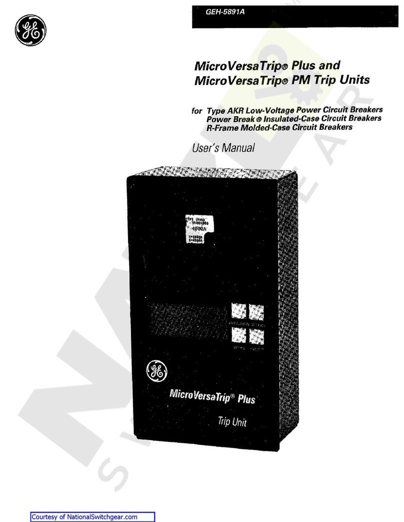
GE PVDB-28kV User manual

GE

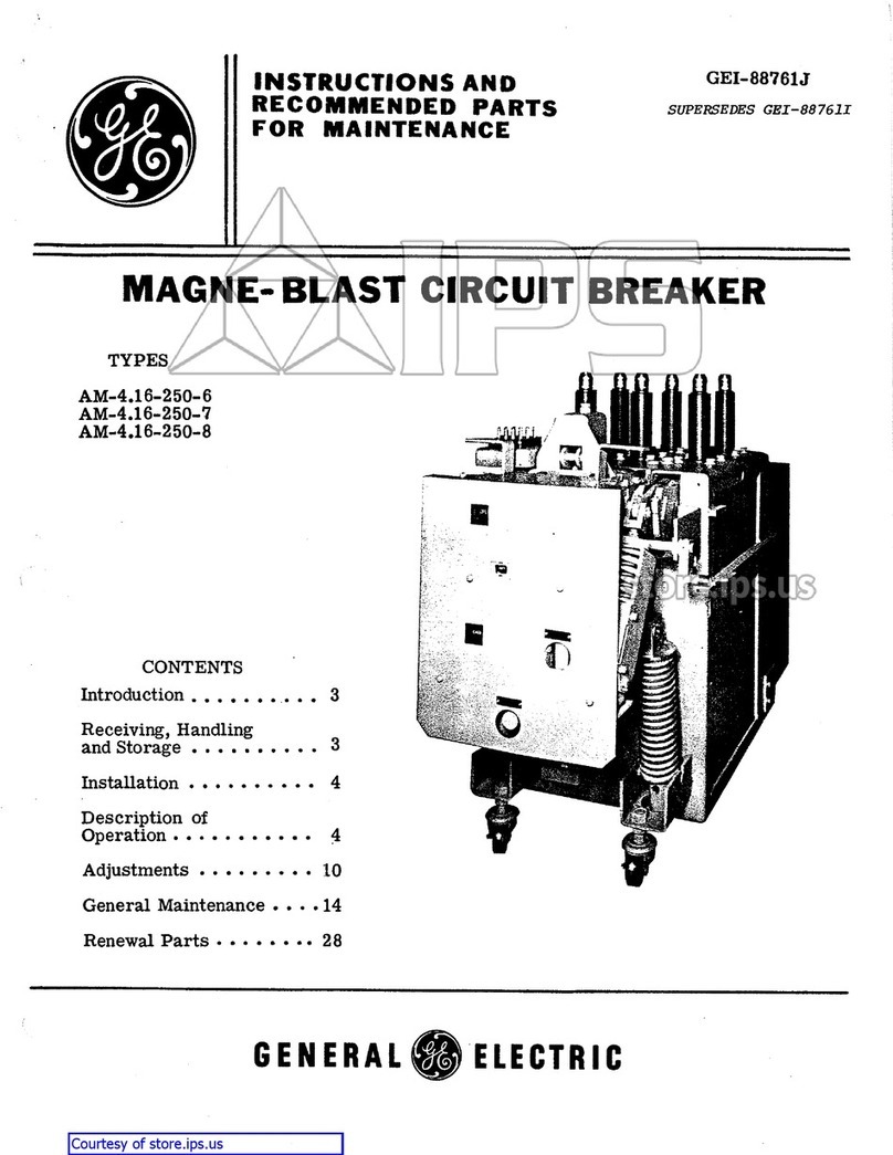
GE PVDB-28kV User manual

GE Power Break II User manual

GE

GE Power Break II User manual

GE Rapid TripFix User manual

GE

GE Rapid TripFix User manual

GE WavePro LVPCB User guide

GE

GE WavePro LVPCB User guide

GE Magne-Blast AM-13.8-1000-3H User manual

GE

GE Magne-Blast AM-13.8-1000-3H User manual

GE AM-4.16-250-9 User manual

GE

GE AM-4.16-250-9 User manual

GE GL 310 F1/4031 P/VR User manual

GE

GE GL 310 F1/4031 P/VR User manual
GE AKR-30 Series User manual

GE

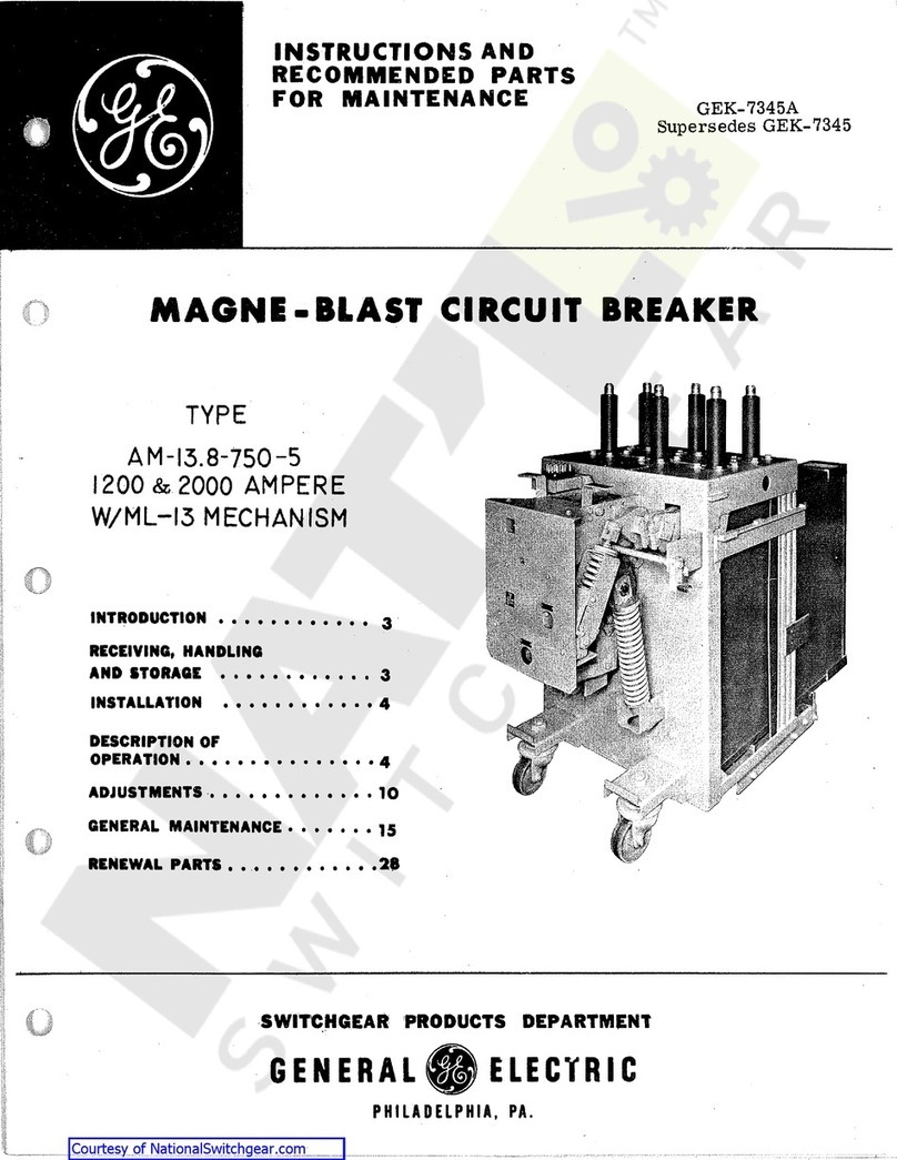
GE AKR-30 Series User manual

GE AM-4.16-250-6C User manual

GE

GE AM-4.16-250-6C User manual

GE EntelliGuard GT-H User manual

GE

GE EntelliGuard GT-H User manual

GE AK-1-15 Series Owner's manual

GE

GE AK-1-15 Series Owner's manual
GE GL 311 F3/4031 P/VE User manual

GE

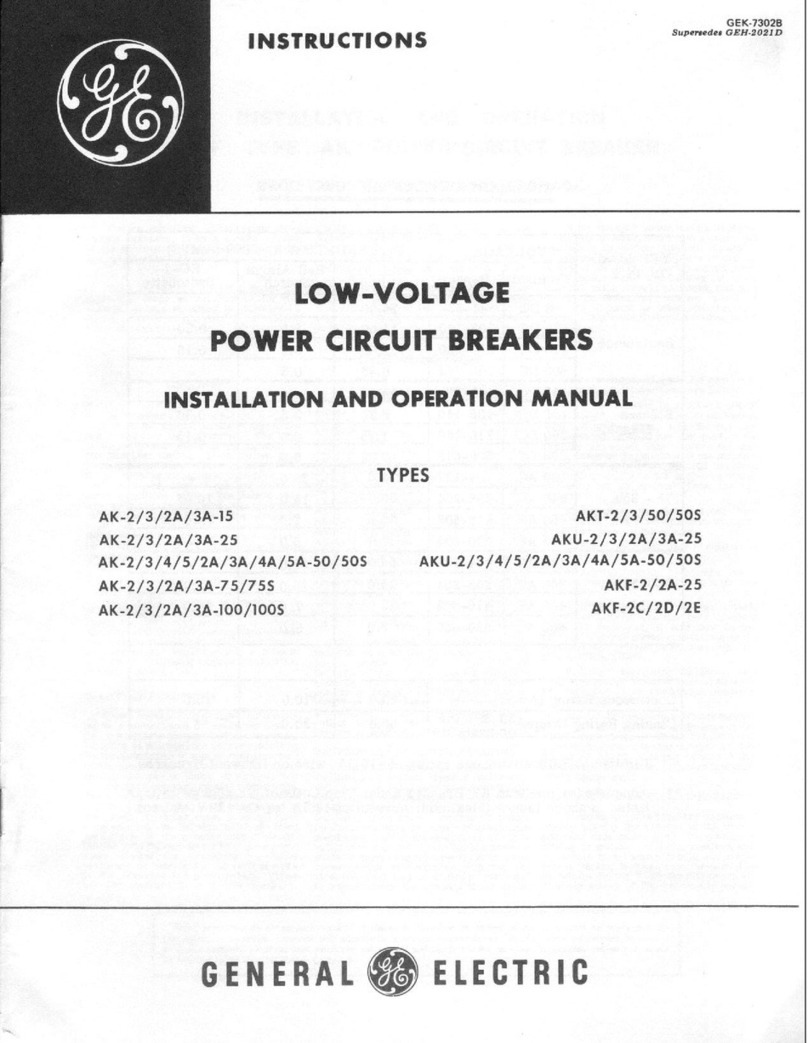
GE GL 311 F3/4031 P/VE User manual

Popular Circuit Breaker manuals by other brands

Siemens 3VT9524-4TG30 quick start guide

Siemens

Siemens 3VT9524-4TG30 quick start guide

Acrel ASCB1 Series Installation and operation manual

Acrel

Acrel ASCB1 Series Installation and operation manual

ABB SACE Emax 2 E2.2 manual

ABB

ABB SACE Emax 2 E2.2 manual

Eaton NOVA LBS 15 Installation and operation instructions

Eaton

Eaton NOVA LBS 15 Installation and operation instructions

ABB SACE Emax E1 quick start guide

ABB

ABB SACE Emax E1 quick start guide

Siemens SIRIUS 3RV1742 Original operating instructions

Siemens

Siemens SIRIUS 3RV1742 Original operating instructions

WEG FHU ACW125 installation instructions

WEG

WEG FHU ACW125 installation instructions

TERASAKI NHP TemBreak PRO P160 Series installation instructions

TERASAKI

TERASAKI NHP TemBreak PRO P160 Series installation instructions

Siemens Sentron 3VA9157-0PK1 Series operating instructions

Siemens

Siemens Sentron 3VA9157-0PK1 Series operating instructions

hager TS 303 User instruction

hager

hager TS 303 User instruction

ETI EFI-4B Instructions for mounting

ETI

ETI EFI-4B Instructions for mounting

Gladiator GCB150 Installation instruction

Gladiator

Gladiator GCB150 Installation instruction

nader NDM3EU-225 operating instructions

nader

nader NDM3EU-225 operating instructions

Eaton 50DHP-VR Instruction handbook

Eaton

Eaton 50DHP-VR Instruction handbook

ABB SACE Emax 2 E6.2 Instruction handbook

ABB

ABB SACE Emax 2 E6.2 Instruction handbook

Gewiss 90 RCD Installation

Gewiss

Gewiss 90 RCD Installation

OEZ LFN Instructions for use

OEZ

OEZ LFN Instructions for use

Eaton Power Defense PDG2 Instruction leaflet

Eaton

Eaton Power Defense PDG2 Instruction leaflet

manuals.online logo
manuals.online logoBrands
  • About & Mission
  • Contact us
  • Privacy Policy
  • Terms and Conditions

Copyright 2025 Manuals.Online. All Rights Reserved.