Rollei Actioncam 300 User manual

www.rollei.de
Studio 300 / 500
Studioblitz | Studio Flash
ANLEITUNG AUF DEUTSCH
MANUAL IN ENGLISH

22
ENGLISH
Before the First Use
Before using the device for the first time, please read the operating
instructions and safety instructions carefully.
Keep the operating instructions together with the device for future use. If other peo-
ple use this device, make this manual available to them. If you pass on the device to
a third party, this manual is part of the device and must be supplied with the device.
Explanation of Symbols
The following symbols are used in this manual, on the flash or on the packaging.
Products marked with this symbol comply with all relevant Community
legislation of the European Economic Area.
Products marked with this symbol are operated with alternating current.
With protection class I (protective earthing), all electrically conductive
housing parts of the unit are connected to the protective earth conductor.
For indoor use only. Devices with this symbol may only be operated
indoors (dry environment).

23
4
7
4
8
5
6
1
Overview
Carrying handle
Tilt lock
Lamp stand lock
Bowens S-type bayonet
Flash tube
LED modelling light
Bayonet release
Umbrella holder and
umbrella lock
Minus ”-“ button
LC display
Photocell (infrared sensor)
Modelling light / acoustic signal
Test flash button
Sync connection
Connection for mains cable and
Fine-wire fuse
Plus ”+“ button
Radio mode button
SET button
On/Off switch
17
18
19
16
10
12
11
13
14
15
9
1
2
3
4
5
6
7
8
9
10
11
12
13
14
15
16
17
18
19
2
3

24
ENGLISH
Display Ads
Radio mode
Power output M: 3.0 – 9.0
Groups A / B / C / D / E / F / G / H / I / J / L / O / P / Q / S / U
Radio channels 0 – 31
Photocell on / off
Acoustic signal
Modelling light on / off, proportional
EasyCap display
20 23
24
25
26
27
22
21
20
21
22
23
24
25
26
27

25
Operation
1) General notes on commissioning
– Please check the scope of delivery for completeness:
1 x Rollei Studio 300 / 500 studio flash, 1 x protective cap, 1 x mains cable 4.5 m,
1 x instruction manual.
– Before using the flash for the first time, please read the operating instructions
completely and observe all warnings and safety instructions.
– Mount the flash on a lamp tripod, lock it in place using the lamp tripod lock [3].
Adjust the tilt of the flash with the tilt lock [2].
– Remove the protective cap from the flash tube. To do this, pull the bayonet
release button [b] to the rear, turn the protective cap to the left and remove it to
the front.
– Put on the desired light shaper / flash umbrella. The flash unit is equipped with
an umbrella holder for reflector/translucent umbrellas and the Bowens S-type
bayonet [a] for the use of a wide variety of light shapers (softboxes, reflectors,
beauty dishes, etc.).
a) Bowens S-type bayonet (3x)
b) Bayonet release
c) Bayonet pins (3x on the light shaper) a
c
b

26
ENGLISH
Operation
– Insert the light shaper with the three bayonet pins [c] into the corresponding re-
cesses on the flash unit and lock it by briefly turning it to the right until it audibly
clicks into place.
– To remove the light shaper, pull the bayonet release button [b] to the rear, turn
the light shaper to the left and pull it off to the front.
– Connect the unit to the mains using the mains cable supplied.
– To switch on, press the on/off switch [19] on the back of the unit, the LC display
switches on.
– Select the various unit functions (see page 28ff.).
– To switch off, press the on/off switch [19] on the back of the unit, the LC display
switches off.
– Please allow the unit to cool down before packing it for transport or storage. If
necessary, remove the light shaper or umbrella, disconnect the flash from the
mains and replace the protective cap on the flash tube.
2) Notes on synchronisation
Simultaneous triggering of camera and flash (synchronisation) is possible via:
– A sync cable (3.5 mm mini-jack), for direct connection between camera and flash
or for connecting flash triggers from other manufacturers to the sync socket [14].
– The photocell / infrared sensor [11] built into the flash. For this you need an
infrared remote trigger for your camera or you trigger the flash as a slave flash
via the light pulse of another flash.
– The radio receiver (2.4 GHz) built into the flash. For this you need one of the
compatible Jinbei radio remote controls TR-Q7, TR-V6 or TRS-V, or the Rollei
Professional Radio Transmitter Mark II.

27
Operation
3) Notes on radio operation
– When using radio remote controls, please note that the radio channel and (de-
pending on the type of remote control) also the group must be set identically for
correct functioning on the flash and on the remote control.
– Please note that the radio frequency (2.4 GHz) used by these devices is shared
with other users / devices. Interference cannot be ruled out due to this. If neces-
sary, change the radio channel to avoid interference.
4) Notes on the camera in continuous shooting mode
– When the camera is switched to continuous shooting mode, please reduce the
power output of the flash unit so that the flash charging time keeps up with the
continuous shooting speed of the camera.
5) Notes on overheating protection
– If there is a danger of overheating, the overheating protection on the flash unit
will switch on automatically. Please interrupt your work immediately and let the
flash unit cool down until the ”OH” symbol disappears from the display. You can
then continue your work.
– If the symbol ”OF“ appears on the display, the flash has switched off because it
has worked over 1000 times continuously at an output power of over 8.0. Again,
wait until the flash has cooled down to continue your work.

28
ENGLISH
Operation
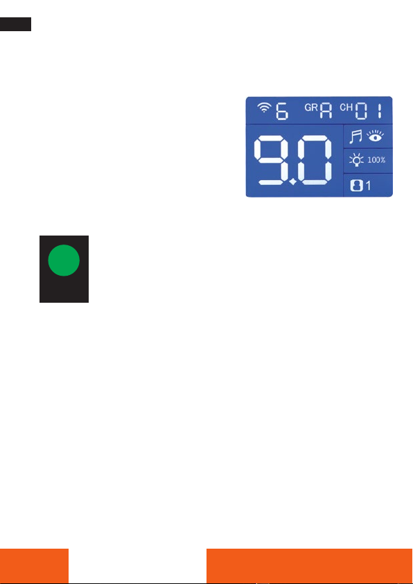
1) Flash output setting
– The flash output from 3.0 to 9.0 can be set in 1/10 or whole f-stop increments.The
maximum power is shown in the display [10] as 9.0.
– To adjust in 1/10 f-stop increments, press
the Minus-button [9] or the plus button
[16] to the desired value.
– For adjustment in whole f-stop steps,
keep the minus button ”-“ [9] or the plus
button ”+“ [16] pressed for a longer
time.
Test flash
– Press the test button [13] to trigger a test flash.
– With a green signal, the test button [13] indicates that the capacitor
is fully charged and the flash is ready to flash again. When the flash
is ready, an acoustic signal sounds at the same time, provided it is
switched on with the button [12].
Modelling light / acoustic signal
– With a short press on the button [12], you switch the modelling light on and off
and select between proportional power, 100% power and off. The symbol [26]
appears on the display.
– When the modelling light is switched on, it also functions as a visual ready
indicator for the flash charging process. When a flash is triggered, it switches
off. When the flash is ready again, it switches on again. If the acoustic signal is
switched on, the modelling light does not function as a visual ready indicator.
– A long press on the key [12] switches the acoustic signal on and off. The
symbol [25] appears on the display.
Test

29
Operation
Radio mode
Press the radio mode button [17] to switch the flash to radio mode. The symbol [20]
on the display starts flashing.
– Press the ”minus“ or ”plus“ button [9/16] until the display shows ”7“. Then the
flash is set for use with the Rollei Professional Radio Transmitter Mark II or the
Jinbei TR-Q7.
– Press the ”minus“ or ”plus“ button [9/16] until the display shows ”C“, ”N“, ”S“
or ”F“ for using the radio remote controls.
Wireless Remote Control
TTL-C (Canon remote control)
TTL-N (Nikon remote control)
TTL-S (Sony remote control)
TTL-F (Fujifilm remote control)
CH/GR (CH & GR remote control)
Canon RT radio „ID“ numbers can be set between 00 – 99 / AU.
Flash and Canon speedlites can be synchronized when CH & ID numbers keep the
same.
Press the ”minus“ or ”plus“ button [9/16] until the display shows ”Radio
6“. The flash is then set for use with the Jinbei radio remote control
TR-V6.
Press the ”minus“ or ”plus“ button [9/16] until the display shows ”Radio
0“. Then the flash is set for for use with the Jinbei TRS-V radio remote
control.
A long press on the radio mode button switches the radio mode off.

30
ENGLISH
Operation
Radio channels and groups
Press once the SET button [18] to set the desired radio channel from
”0“ to ”31“. The display starts flashing. Press the minus button ”-“
[9] or the plus button ”+“ [16] to set the possible values. The set
value is automatically confirmed after 2 seconds.
Press the SET key [18] again to set the desired group to
A – J / L / O / P / Q / S / U. The display starts flashing.To set the
values in question, press the ”Minus“ key [9] or the ”Plus“ key [16].
The set value is automatically confirmed after 2 seconds.
Note: The values set on the flash for channel and group must match the values set
on the radio remote control. Group settings are not available with the TRS-V radio
remote control.
Photocell / Slave mode
Please press buttons [17] and [18] simultaneously to switch the photocell (infra-
red sensor) for slave mode on or off. The symbol [24] appears on the display. Now
the flash is triggered via the flash light of other flash units (studio, camera, clip-on/
system flash) or via an infrared remote trigger.
Note: Please note that this method of triggering is highly dependent on the en-
vironment and the positioning of the individual flash units in relation to each other.
Note: It is not guaranteed that all camera models are always supported.There
may also be restrictions in functionality or in combinations of different technical
possibilities.

31
Operation
EasyCap-Modus
Long press the SET key [18] to activate EasyCap mode.The corresponding icon [27]
appears in the display.
Briefly press the ”minus“ or ”plus“ key [9/16] to set ”1“ for the first flash, ”2“ for
the second flash and ”1/2“ to end the EasyCap mode and confirm your entry by
briefly pressing the SET key [18].
Notes on Changing the Flash Tube
Please note the following instructions for changing the flash tube:
Make sure that the unit is switched off and disconnected from the power supply.
Wait until the flash tube has cooled down before changing it. Always use clean
cotton gloves or a microfibre cloth to change the flash tube.
Fig. 1: Unwind the twisted ignition wire from the
flash tube holder and carefully pull the flash tube out
of the unit.
Fig. 2: To insert a new flash tube, support the legs of
the flash tube and carefully push the flash tube into
the end position. Then wrap the ignition wire around
the flash tube holder again.

32
ENGLISH
Troubleshooting / Fault Rectification
Unit does not switch on
– Please check that the mains cable is correctly seated.
– Please check (if necessary with a suitable measuring device) whether there is
voltage for the mains cable at the socket.
– Please check the appliance fuse and the house fuse. Replace the fuse(s) if neces-
sary.
Modelling light does not work
– Please check whether the modelling light is switched on.
Flash does not fire
– Disconnect the unit from the power supply. Please check that the flash tube is
correctly seated and that the ignition wire is correctly connected. Never touch
the flash tube or the ignition wire with your bare hand. Use cotton gloves or a
microfibre cloth.
– Replace the flash tube if necessary (see page 31).
– Please check whether the overheating mode has been activated on the unit. In
this case, the symbol appears on the LC display. Please interrupt your work imme-
diately and let the flash unit cool down until the symbol ”OH” on the display
disappears. The unit is then ready for operation again.
Flash does not fire via the photocell (infrared sensor)
– Please check whether the photocell is switched on.
– Please check whether the photocell is covered.

33
Troubleshooting / Fault Rectification
Flash does not synchronise
– Please check the cable connection between camera / flash or flash trigger / flash.
If necessary, use a different sync cable.
– When using a radio remote control, please check that the
batteries / accumulators of the radio remote control are not empty.
– Please check whether the radio remote control is correctly seated in the hot shoe
of the camera.
– Please check whether identical radio channels and groups are set on the flash
and on the radio remote control.
– Please check whether other devices in the vicinity operate with the same radio
frequency and switch them off if necessary.
Error messages
– ”OU“ stands for ”over use“. The main capacitor is defective and you must give
the flash to a suitable specialist for repair.
– ”OT“, stands for ”over time“.The charging system is defective and you must
hand the flash over to qualified personnel for repair.
If a problem persists, please contact your Rollei dealer.

34
ENGLISH
Technical Data
Model Studio 300 Studio 300
Power 300 Ws / GN60 500 Ws / GN72
Power control M: 3.0 – 9.0 (1/64 – 1/1) |
setting in whole f-stops or in 1/10 steps
Flash mode M
Sync Mode Normal
Recycling time 0.1 – 0.8 s 0.1 – 1.0 s
Flash duration (t=0.5) 1/800 – 1/2,200 s
Colour temperature 5,500 ± 200 K
Modelling light 15.0 W LED (4,100 K ± 200 K)
Modelling light control Off | proportional | 100% full
Radio receiver integrated
2.4 GHz (Frequency band: 2.402 – 2.480 GHz /
max. radiated power: 6 dBm)
32 radio channels (0 – 31)
16 groups (A, B, C, D, E, F, G, H, I, J, L, O, P, Q, S, U)
Flash release Radio
sync cable (3.5 mm mini jack DC 5.0 V)
photocell (slave)
Test flash trigger
Cooling Fan | Overheating protection
Other features LC display | Ready indicator (acoustic, optical)
Acoustic signal (can be switched off) | Photocell on /
off | Overheating warning „OH
Bowens S-type bayonet | umbrella holder
tripod mount (5/8“)
Carrying handle

35
Technical Data
We reserve the right to update functions or parameters without further notice.
Modell Studio 300 Studio 300
Power supply AC 195 ~ 245 V | 50/60 Hz | Fuse 15.0 A
Compatible radio remote
controls
Rollei Professional Radio Transmitter Mark II
Jinbei TR-Q7
Jinbei TR-V6 for cameras with standard ISO hot shoe
Jinbei TRS-V for cameras with standard ISO hot shoe
Dimensions 27.0 x 13.5 x 20.5 cm (L x W x H)
Weight 1.3 kg 1.5 kg
Box Content Rollei Studio 300 / 500 Studioblitz, protective cap,
power cord and user manual

36
ENGLISH
Safety Instructions
Danger from electric current!
Faulty electrical installations or excessive mains voltage can cause electric shock.
– Only connect the product if the mains voltage of the socket corresponds to the
specifications on the type plate.
– Connect the product to an easily accessible power outlet so that you can quickly
disconnect it from the mains in case of problems.
– Use only the supplied power cord.
– Do not use the product if it is visibly damaged or if the cable is defective.
– If the product or its accessories are damaged, they must be replaced or repaired
by the manufacturer, its service department or a similarly qualified person to
prevent hazards.
– The housing must not be opened and repairs must only be carried out by a
qualified technician. To do this, contact a specialist workshop. Any liability and
all warranty claims are excluded in the event of repairs by the user, improper
connection or incorrect operation.
– If you do not use the product for a long period of time, always disconnect it from
the power source.
– Protect the product from moisture. Do not touch the product with wet/damp
hands or immerse it in water.
– This product is not waterproof! Do not use this product in the rain or in wet environ-
ments. Never touch the product during a thunderstorm.
– Before disconnecting the power, turn off the power at the main switch.
– Do not store or use the flash unit in locations where it is exposed to strong elec-
tromagnetic fields or dust. Keep the unit away from other sources of interference.
– Switch the flash unit off and disconnect it from the power supply when changing
the flash tube.

37
Safety Instructions
Attention!
– Never use the power cord as a carrying handle.
– Keep the product and accessories away from naked flames, hot surfaces and
highly flammable materials.
– Lay the power cord so that it does not present a tripping hazard.
– Do not bend the power cord or lay it over sharp edges.
Attention!
Danger for children and persons with limited physical, sensory or men-
tal abilities (e.g. partially disabled, older persons with limited physical
and mental abilities) or lack of experience and know-how (e.g. older
children).
– This product may be used by persons with reduced physical, sensory or mental
abilities or lack of experience and know-how, provided that they are supervised
or have received instructions for the safe use of the product and understand the
potential hazards arising from its use. Children must not play with the product.
The product must not be cleaned or maintained by children. Keep children under
eight years of age away from the product and its accessories.
– Do not insert any objects into the product.
– Do not leave the product unattended during operation.
– The product is not a toy. Keep the product, accessories and packaging materials
away from children and pets to prevent accidents and suffocation.
– For photographic lighting purposes only. Not suitable for permanent room light-
ing.

38
ENGLISH
Safety Instructions
– Do not film car, bus, bicycle, motorbike or train drivers while driving
with this product. The driver may be blinded and cause an accident. This also
applies to unlisted persons or groups if possible glare could cause an accident.
– Do not shine directly into the eyes of people or animals as this may cause dama-
ge to the retina, visual disturbances and even blindness.
– Ensure adequate ventilation during operation. Never cover the ventilation slits of
the unit.
– Do not use or store the unit in high temperatures or in closed rooms with direct
sunlight. The product should not be used in ambient temperatures above 40°C.
– Please note that the flash tube, modelling light and a connected reflector can be-
come very hot during operation. Do not touch these parts during or immediately
after operation. Allow the unit components to cool down before replacing the
flash tube or reflector.
– Handle glass parts such as the flash tube with care so that the glass is not
broken. Do not touch the flash tube with bare hands, use clean cotton gloves or a
microfibre cloth. Small residues of skin grease can cause the flash tube to burst.
– Make sure that the flash tilt lever is firmly tightened before using the unit and
connecting accessories to it.
– Mount the flash unit on a tripod with sufficient load-bearing capacity and set up
the tripod so that it cannot tip over or slip.
– Allow the flashgun to cool down before packing it for transport or storage.
Other manuals for Actioncam 300
2
Table of contents
Other Rollei Flashlight manuals