Rollerdor RD20X2ANSA User manual

Rollerdor RD20X2ANSA Control Box, Edition 2022/1
Installation Guide for Roller Garage Doors
RD20X2ANSA Control Box
Edition 2022/1

2
Rollerdor RD20X2ANSA Control Box, Edition 2022/1
1. INSTALLING RECEIVER BOX
(SAFETY EDGE)
1 To gain access to the board of the panel remove the dark
grey plastic cover at the bottom and this will reveal a
screw in each corner and the spare fuses for the board,
remove these screws and the light grey cover will come
away (fig.1).
2 Remove the top white plastic light cover by squeezing
each side and easing away the cover and disengaging the
top clip (fig.2).
3 Place the Receiver box on the wall with the cable
pointing downwards at a comfortable height to operate
the push buttons, but out of the easy reach of children.
Between 1500mm up from the floor and 300mm down
from the roof/ceiling is recommended (fig.3) the lid of
the box that the unit came in can be used as a template
for the 3 fixings.
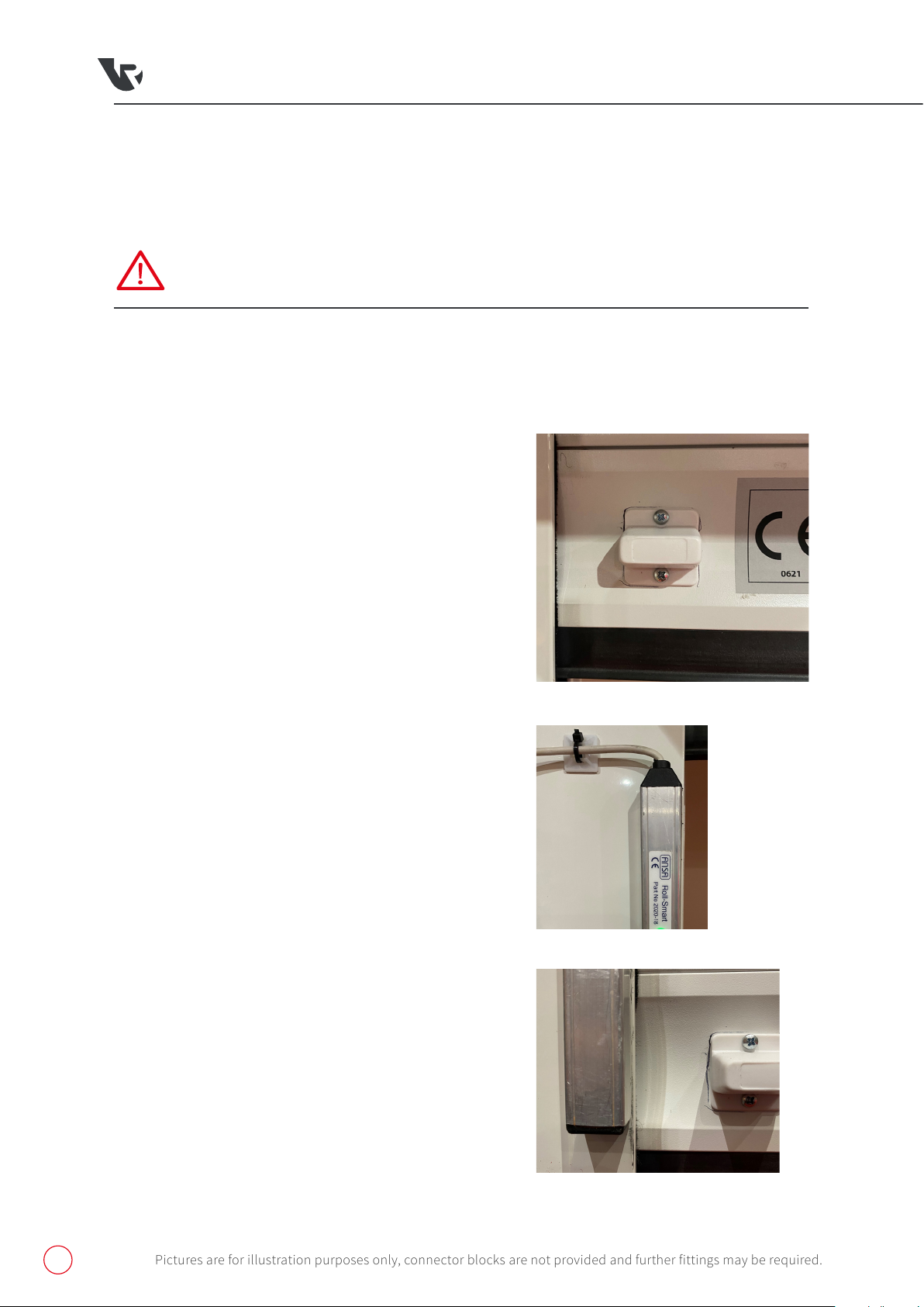
4 If you have a safety brake with a cable then run the two
core cable from the safety brake end across to the same
end as the receiver box, making sure to securely fix the
cable out of the way of the working mechanism.
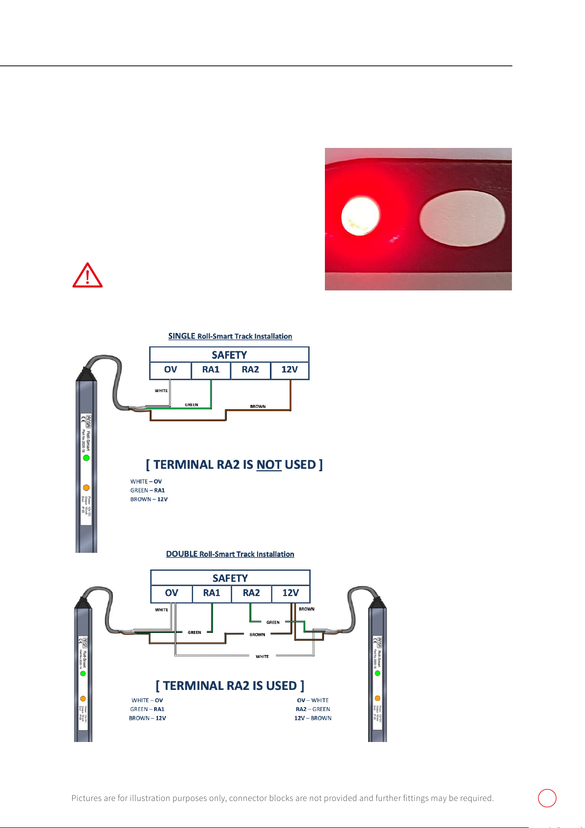
5 Motor Wiring: Connection of the motor's open and close
cables (black & brown) must suit the motor handing as
per the diagram (fig.4).
6 Safety Brake: if you have a safety brake connection then
remove the link from COM24V and STP (fig.5), connect in
the brown 2 core cable to COM24V and blue 2 core cable
to STP (fig.6).
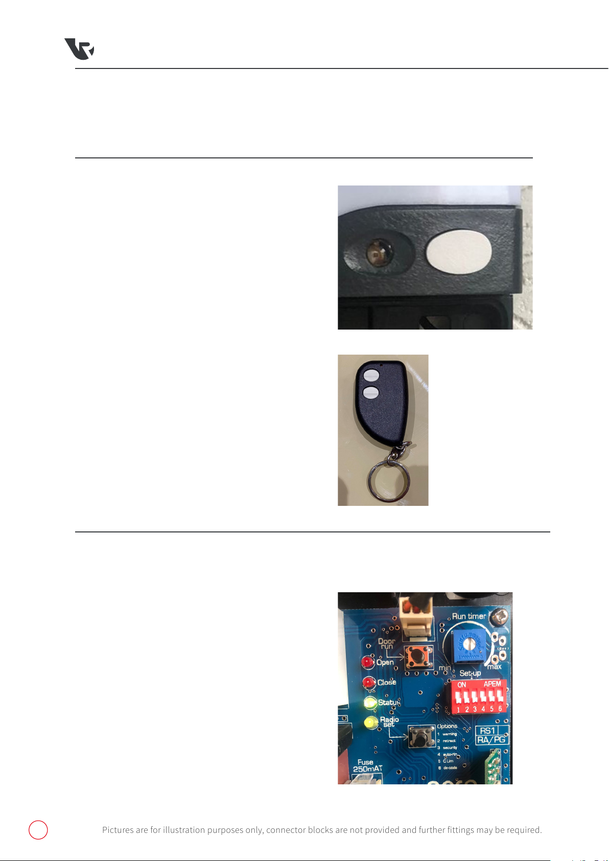
7 Aerial: Steel wire aerial must be connected to terminal
EXT A and be facing down out of the bottom of the unit.
8 Optional Extra Alarm System: if you have purchased
an alarm system it will need to be fixed to the wall and
connected to the receiver box, first enter the cable from
the alarm into the box through one of the grommets on
the bottom and run the cable around and up to the left
hand side top corner where the connector is, simply push
fit to connect (fig.7), then you know how much cable is
available to install the alarm to the wall (fig.8)
WARNING: do not install the alarm module next
to the radio receiver tile.
fig.1
Pictures are for illustration purposes only, connector blocks are not provided and further fittings may be required.
fig.2
fig.4
fig.3

3
Rollerdor RD20X2ANSA Control Box, Edition 2022/1
fig.5
fig.7
fig.6
fig.8
Pictures are for illustration purposes only, connector blocks are not provided and further fittings may be required.

4
Rollerdor RD20X2ANSA Control Box, Edition 2022/1
2. SETTING UP WIRELESS
SAFETY EDGE KIT
(RD20X2 OPTICAL SAFETY EDGE)
PROGRAMMING BASE RAIL UNIT
1 With the power isolated remove link wire from 12v
to PEC (fig.6) and keep safe for later, the control
box is now in hold to run operation for open and
close, if the limits of the motor have not been
set then please set them now using the Door run
button, please be aware the door run button works
sequentially but the LED on the board next to it
will tell you which way it is moving either open or
close. Once limits are set return link wire from 12v
to PEC.
2 Open the door to around chest height so you can
easily access the base rail, on the base rail is 2
pre-drilled holes for the door magnet, these will be
on the same side as the motor or for double doors
there will be holes both sides, attach the magnet
making sure it is the correct way up (fig.9).
3 Close the curtain all the way to the floor, wipe both
of the guide runners to make sure they are clear of
all debris and dust.
4 Attach the smart track to the guide runner on the
same side as magnet, peel off the adhesive strip on
the back and apply to the inner edge of the guide
runner. The track must be straight with the cable
coming out of the top (fig.10) and the bottom of
the rail in line with the magnet on the base rail
(fig.11).
5 Smart Track Wiring: run cables from track to the
receiver box, turn power off and wire in as (fig.12).
6 Commissioning:
(A)Turn power back on and run the curtain to the fully
open position. Turn power o wait 5 seconds then turn
power back on.
fig.9
fig.10
fig.11
Pictures are for illustration purposes only, connector blocks are not provided and further fittings may be required.
WARNING: The Installation of this system MUST be carried out in the order as detailed below.

5
Rollerdor RD20X2ANSA Control Box, Edition 2022/1
Pictures are for illustration purposes only, connector blocks are not provided and further fittings may be required.
fig.12
(B) Press and hold the operation button on the front of the
receiver box next to RED LED (fig.13) for 1 second then release.
(C) Wait 2 seconds then press and release the operation button.
The door will start to close, and will stop just before it touches
the floor. The curtain will then partially reopen to confirm that
the commissioning has been a success.
WARNING: you must not stop the door at any point
during the commissioning cycle. If the door is
stopped or the commissioning doesn’t work please
repeat from Step (A). fig.13

6
Rollerdor RD20X2ANSA Control Box, Edition 2022/1
Handsets that come supplied with the receiver
box are normally programmed in and work in a
sequential operation but if any extra handsets need
programming please follow instructions below.
1 Press and hold the operation button on
receiver box next to the RED LED for roughly
5 seconds and release when the RED LED
goes out (fig.13 & fig.14)
2 The RED LED will flash once to say it
is programming mode: With the new
unprogrammed handset in hand, press and
release the top button (fig.15) and the red
LED will flash once again, repeat for every
handset to be added.
3 After programming all desired handsets
wait 30 seconds for the RED LED to come
back on solid and the door is out of
programming mode and ready to use, test
handset to check and repeat the process if
programming hasn’t worked.
SEQUENTIAL OPERATION
1 Turn mains power off.
2 Move dip switch number 6 in the up position
(fig.16).
3 Turn mains power on, the YELLOW LED “set
radio” will light up for 5 seconds.
4 Turn mains power off, Move dip switch number
6 back down, turn mains power on. All handsets
are wiped.
CLEARING MEMORY OF REMOTE
CONTROL HANDSETS
fig.16
3. PROGRAMMING OF REMOTE
CONTROL HANDSETS
fig.14
fig.15
Pictures are for illustration purposes only, connector blocks are not provided and further fittings may be required.

7
Rollerdor RD20X2ANSA Control Box, Edition 2022/1
1 Operation: The unit will automatically arm on closure, a break in alarm signal is triggered if the button rail
is forced open.
2 Alarm LED status: the alarm has a LED status LED light, if the light is GREEN then the door is closed and the
alarm is set; if the LED is RED the door is open and the alarm is off; if the LED is flashing then the door is in
motion or is part open.
3 Activation: Should the alarm be activated it will continue the alarm until either the handset is operated to
reset the alarm or it will automatically reset after 15 minutes.
ALARM SYSTEM
MR
1 Open the door fully, remove the connection going into STOP terminal on the main board (fig.5 / fig.6), the
LED next to Status should turn from GREEN to RED, then turn the power off.
2 Press and hold the Door Run button on the board (fig.16), whilst holding this button down turn the power
on, the RED LED on the box should slowly flash off and on (fig.13).
3 Re-insert the connection into the STOP terminal on the main board (fig.5 / fig.6), the Status LED should
turn back to green.
4 Turn power off and leave for 10 seconds then turn power back on, reset is now complete.
FACTORY RESET
B
A
Pictures are for illustration purposes only, connector blocks are not provided and further fittings may be required.

8
Rollerdor RD20X2ANSA Control Box, Edition 2022/1
4. OPTIONAL EXTRAS
Pictures are for illustration purposes only, connector blocks are not provided and further fittings may be required.
WIRING AS FOLLOWS:
Grey 11 Terminal Block on right hand side (fig.17):
Switches work on a sequential action so from an initial
position of door closed it will be the following cycle:
(open, stop, close, stop, open etc).
IMP - UP & DOWN Wire.
COM - Common wire from supply to switch.
Rocker Switch (fig.18):
4– Up wire
3– Down wire from rocker switch
5– Common wire for the supply to the switch
Fit Link wire from 5 to 2
To open rocker switch remove screws
Key Switch (fig.19):
Right Block 13 – Up wire
Left Block 14 – Down wire
Right Block 14 – Common wire for the supply to the switch
Left Block 13 – Right Block 14 Link wire between terminals
To open key switch remove screw then turn key
a quarter turn.
HARD WIRED ROCKER / KEY SWITCH
fig.19Bfig.19A
fig.18
fig.17
Link wire
Up wire
Down wire
Common wire

9
Rollerdor RD20X2ANSA Control Box, Edition 2022/1
Pictures are for illustration purposes only, connector blocks are not provided and further fittings may be required.
WIRELESS KEY PAD
INSTALLATION
1 Undo and remove the two back-plate securing screws from the top and bottom of the unit and remove the
back-plate.
2 Using the back-plate as a template, mark the positions of two suitable fixing holes onto the wall then
secure the back-plate to the wall using the plugs and fixing screws provided.
3 Remove the battery cover from the rear of the keypad and fit the 9 volt battery supplied. Refit the battery
cover and fixings. Push the keypad onto the back-plate and secure in place with the two fixing screws.
fig.20
PAIRING USING ACCESS CODE
1 The keypad is supplied with factory pre-set master code number "9999"and factory access code number
"1234".
2 To pair keypad to receiver box, press and hold the operation button on receiver box next to the RED LED for
roughly 5 seconds and release when the RED LED goes out (fig.13 & fig.14).
3 The RED LED will flash once to say it is programming mode: Enter the factory access code “1234" (the LED
keys flash to confirm each key entry and then flash twice once full code has been entered to indicate the
correct access code) the red LED on the box will flash once again to confirm programming.
4 Wait 30 seconds for the RED LED to come back on solid and the door is out of programming mode and ready
to use, test keypad code to check and repeat the process if programming hasn’t worked.

10
Rollerdor RD20X2ANSA Control Box, Edition 2022/1
Pictures are for illustration purposes only, connector blocks are not provided and further fittings may be required.
OPERATION
Entering your personal access code turns on the keypad and operates the control unit, A 20 second time delay
is activated and you may press any numerical key, 0- 9 (excluding # or *) to operate the control box which is in
sequential operation ( down, stop, up, stop etc.)the same manner as a key fob transmitter normally used to
operate the Receiver Box.
KEYPAD FEATURES
1 At night the * key can be pressed to illuminate the keypad.
2 Every number entered is confirmed by the LED keys flashing.
3 If an incorrect access code is accidentally entered, press * and re-enter the correct code.
4 Flat battery warning - when using the keypad, the LED keys will flash rapidly if the battery is low, indicating
the battery needs replacing.
5 The Keypad has an anti-tamper feature - if 6 - 9 incorrect random access codes are entered [or 36 incorrect
keystrokes] the unit will automatically switch off for 10 minutes. If the battery is disconnected in an
attempt to defeat the anti-tamper, the time out restarts when the battery is reconnected.
CHANGING ACCESS CODE
For security reasons it is essential that the access code number is changed to another 4, 5 or 6 digit number these
numbers can be in any combination of numbers 0-9, excluding # and *.
To change access code follow this sequence: press # master code # existing code # new code # new code. The LED
keys flash twice confirming the new access code is acknowledged. (Example from "1234" to "5689", you follow this
sequence: press # 9999 # 1234 # 5689 # 5689.) WARNING: You must keep this new unique access code safe as if lost or
forgotten the Keypad will need to be replaced, which is not covered under warranty.

11
Rollerdor RD20X2ANSA Control Box, Edition 2022/1
5. OPERATING DIAGNOSTICS
Pictures are for illustration purposes only, connector blocks are not provided and further fittings may be required.

12
Rollerdor RD20X2ANSA Control Box, Edition 2022/1
Rollerdor Ltd
10 & 12 Jarrold Way
Bowthorpe Employment Area
Norwich
Norfolk NR5 9JD
+44 (0)1603 743215
sales@rollerdor.net
www.rollerdor.net
Company Registration Number. 10676267
Registered Oice Address:
Rollerdor Ltd, Bankside 300 Peachman Way,
Broadland Business Park, Norwich,
Norfolk, United Kingdom, NR7 0LB
Edition 2022/1
Table of contents
Other Rollerdor Garage Door Opener manuals
Popular Garage Door Opener manuals by other brands

Chamberlain
Chamberlain LiftMaster 3280cm 1/2 HP owner's manual

Edison
Edison Autoslide installation manual

Etdoor
Etdoor 600E Installation instructions and user guide

Chamberlain
Chamberlain WD822KD owner's manual

Cardin Elettronica
Cardin Elettronica 311/GL124EBSS instruction manual

BFT
BFT KR92522800003 Installation and user manual

Overhead door
Overhead door 65A Installation and operating instructions

Chamberlain
Chamberlain LM3800TXSA manual

Chamberlain
Chamberlain Smart Garage MYQ-G0401 quick start guide

RIB
RIB AA33694 manual

GOGOGATE
GOGOGATE Garage Door Opener user manual

Automatismos Pujol
Automatismos Pujol Marathon Pro III manual