7
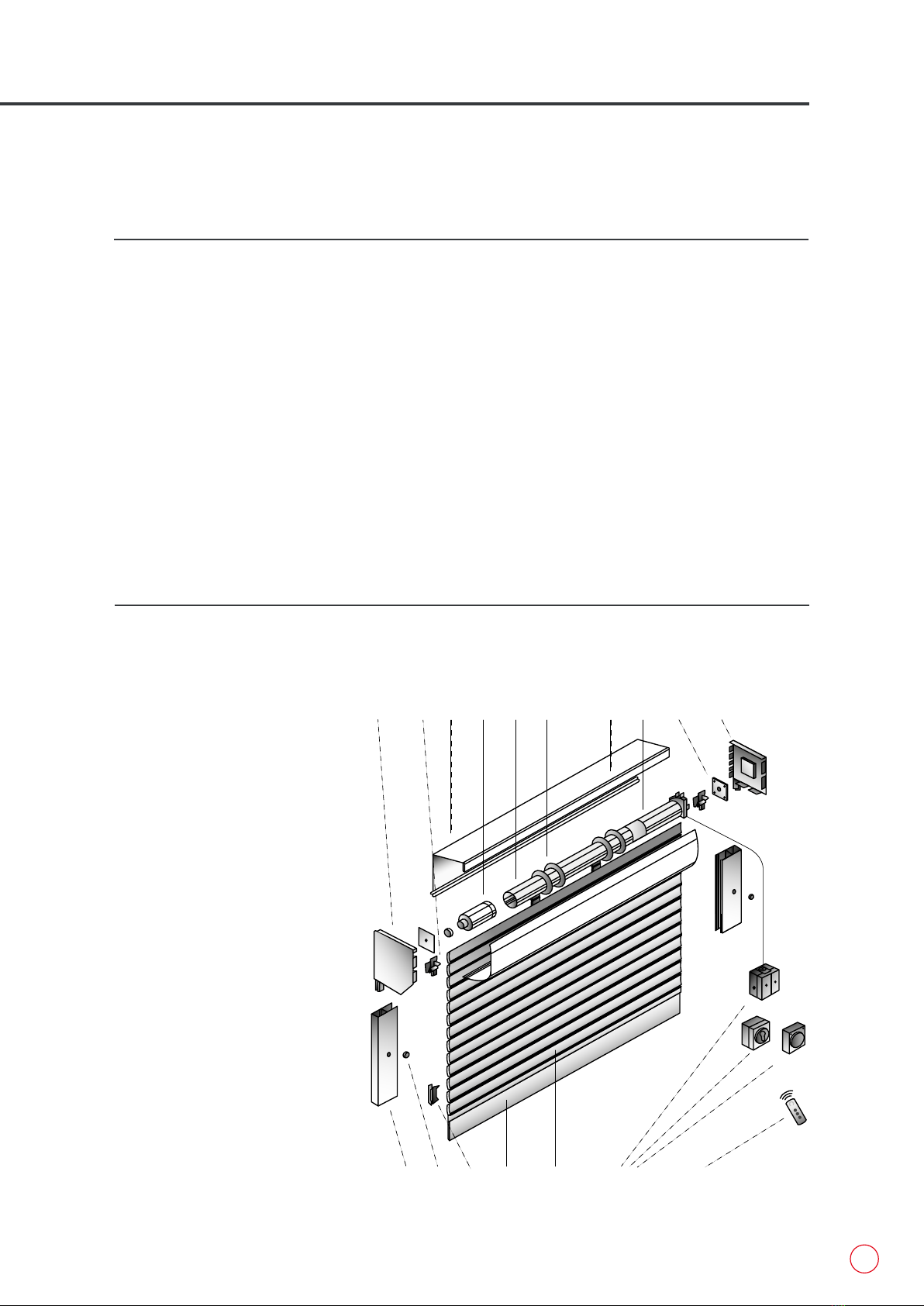
3. INSTALLING HEADER ASSEMBLY
1 Place your hop ups / step ladders
and one guide runner each side of
the opening.
2 With one person each end, lift the
header assembly by the header
plate up and into place, then guide
the locating stem at each end into
the hollow section of guide runners
(this can be made easier by slightly
angling the header if there is not
enough room to simply drop the
locating stem in) (fig.3.1).
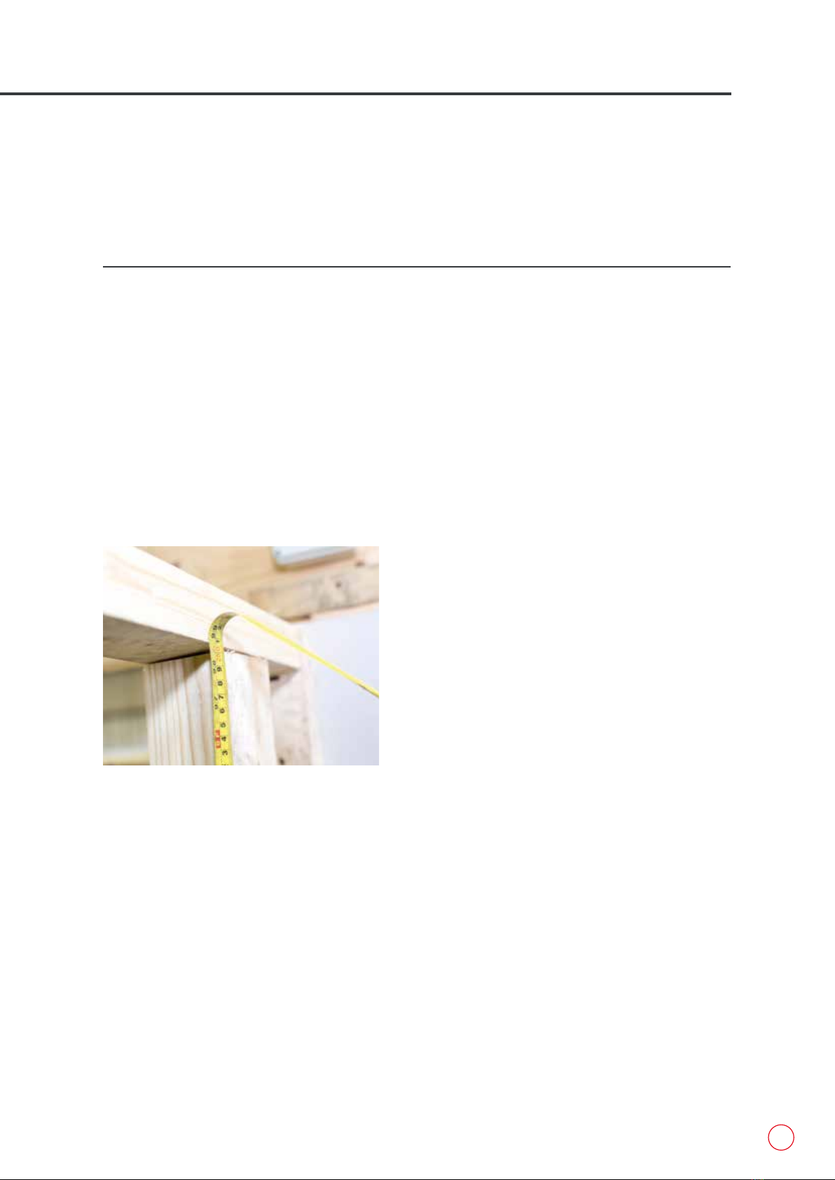
3 Lift the whole unit flush into place
and check that the top box and
guide runners are plumb level and
square (fig.3.2 & fig.3.3).
4 Drill a 7mm fixing through the
top hole in the guide runners and
secure into place (fig.3.4).
5 Check the case and guide runners
are still level and square, then
proceed to drill a 7mm fixing
through the remaining holes,
remembering to check the guide
runners are square and plumb after
each fixing.
6 Check to make sure all fixings have
not caused the front fascia to be
pulled in, as this will rub against
the slats causing damage and
scratching to the face.
7 Seal down the sides and along
the top case (silicon sealant is
recommended).
fig.3.1
fig.3.3
fig.3.2
fig.3.4
8 (For Internal Manual Override system)
Remove winding stem from your winding
handle where it has been taped securely.
9 (For External Manual Override system)
remove metal shaft via the plastic circlet
(p.34, fig.15.1, number 4 ).
10 Remove screw from end of stem and keep
safe for later.
11 Cut cable ties and release curtain, and place
available curtain into guide rails through the
mouth of the guides.
12 Insert winding stem through pre-drilled
hole in header plate. Turn to release
more curtain into guides, roughly 4
slats in total, remove winding stem and
keep safe for later.