Rollerdor RD77 User manual

Rollerdor RD77 Econ Roller Garage Door, Edition 2020/2
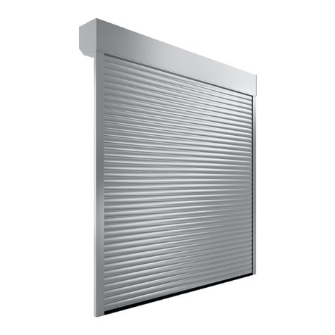
Rollerdor RD77 Econ Roller Garage Doors
Installation Guide
Edition 2020/2

1 2
Rollerdor RD77 Econ Roller Garage Door, Edition 2020/2
CHECKLIST & COMPONENTS
DOOR OVERVIEW
Please check all components for
any visible damage, if there is
any please contact your supplier.
1 Head Plate
2 Guides
3 Full Box
4 Tube End
5 Barrel
6 Security Straps
7 Curtain
8 Motor
9 Motor Plate
10 Guide Rail
11 Plastics Caps
12 End Lock
13 Base Rail
14 Safety Break
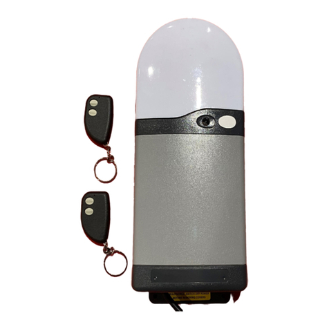
15 Remote Control Fob
16 Switches (if any)
EQUIPMENT REQUIRED
• 2 x Step ladders or hop ups
• Spirit level
• Tape measure
• Power drill
• 10mm A/F Spanner
• 2 x Pozi-screwdrivers
• 7mm Metal drill bit
• 10mm Metal drill bit
• 7mm Masonry drill bit
• Hacksaw
• Small electrical screwdriver
• 4mm A/F Allen key
ROLLERDOR COMPONENT CHECKLIST
• Door Curtain.
• Barrel Assembly (Barrel, Tube End, Security Springs,
Security Collars).
• Head Plate with Motor Attached.
• Head Plate with Safety Break Attached.
• One Pair of Guide Runners.
• Control System with Two Remote Fobs.
• Fixings Kit (Qty 10: 5 x 50 screws 7mm brown rawl plugs, plastic caps
and Qty 1 plastic adjustment wand). Please note: fixings supplied
work on the majority of materials but if you know that you require
specialised fixing please replace with these.
10 11 12 13 7 16 15
1 14 2 3 4 5 6 7 8 9 1
Diagram 1
CONTENTS
02 CHECKLIST & COMPONENTS
04 1. PREPARING SITE FOR INSTALLATION
05 2. HEADER ASSEMBLY CONSTRUCTION
07 3. PREPARING GUIDE RUNNERS FOR INSTALLATION
09 4. INSTALLING HEADER ASSEMBLY
11 5. INSTALLING (TYPE 1) RECEIVER BOX (HOLD TO RUN)
12 6. PROGRAMMING REMOTE CONTROL HANDSETS (HOLD TO RUN)
13 7. INSTALLING (TYPE 2) RECEIVER BOX (HOLD TO RUN)
14 8. PROGRAMMING REMOTE CONTROL HANDSETS
AND PUSH BUTTON (HOLD TO RUN)
15 9. INSTALLING (TYPE 3) RECEIVER BOX (HOLD TO RUN)
16 10. PROGRAMMING REMOTE CONTROL HANDSETS (HOLD TO RUN)
17 11. INSTALLING (TYPE 1) RECEIVER BOX (SAFETY EDGE)
19 12. SOMFY OPTICAL SAFETY EDGE (ROLLIXO RTS)
21 13. INSTALLING CURTAIN TO BARREL
23 14. SETTING MOTOR LIMITS (ALL HOLD TO RUN
AND TYPE 1 SAFETY EDGE)
24 15. SETTING MOTOR LIMITS (SOMFY ROLLIXO RTS ONLY)
25 16. SETTING UP WIRELESS SAFETY EDGE KIT (OPTICAL EDGE)
27 17. SETTING UP WIRELESS SAFETY EDGE KIT (VELOCITY EDGE)
29 18. PROGRAMMING OF REMOTE CONTROL HANDSETS
AND PUSH BUTTON (SAFETY EDGE)
34 19. INSTALLATION OF BACK CASE
35 20. OPTIONAL EXTRAS
41 TROUBLESHOOTING

3 4
Rollerdor RD77 Econ Roller Garage Door, Edition 2020/2
1. PREPARING SITE FOR INSTALLATION
IMPORTANT SAFETY
INSTRUCTIONS
The RD77 must be installed
and operated in accordance
with the instructions supplied;
failure to do so could result
in damage to your door and
compromise your safety.
These fitting instructions are for guidance only, you should always assess your garage
construction for installation as each garage & opening has its own specific needs.
Please read these instructions carefully and in full before commencing the installation
of the roller garage door.
WARNING AND GUIDANCE NOTES
1 At least TWO people are required to install this
product.
2 Prior to installing please remove all rings,
watches and sharp objects to avoid any
possibility of damage.
3 Prior to installing please remove any items of
loose clothing to avoid any risk of entanglement
or injury.
4 Your door comes complete with a 3 pin plug as
standard (this is supplied and must be fitted
with a 13amp fuse) which should be plugged
straight into a 13amp 3 pin switched socket in
the vicinity of your door, should you need any
extra electrical work. This must be carried out
by a suitably qualified person, if you have
any doubts please consult an electrician.
5 Your receiver box should be installed in
a location that is at a comfortable height to
operate the push buttons, but out of the easy
reach of children.
6 Please do not allow children to operate the
push buttons or remote control fobs, as
serious injury can occur from misuse.
7 Warning: you must have a clear line of sight
of the whole of your roller garage door when
the door is in operation. Failure to do so may
result in harm to persons or damage to your
roller garage door.
Drive Through
Width
Estimate Drive
Through Height
Total Door
Height to
Top of Box
Guide
Height
Total Door Width
Including Guides
1 Check all measurements
of your opening (fig1.1) as
well as the measurements
of your new delivered
roller garage door against
your confirmation
(fig.1.2) to make sure
everything is correct.
2 Carefully remove your
old garage door and
frame if applicable.
3 Sweep down the sides
and lintel with a sti brush
and clear all debris.
4 Make sure the opening
is free from any raised
metal or brick work.
Plan Of here To Take The Measurements
RL
Aerial View Of Garage
Notes
Which Side Is The
Power Supply On? Right
4L
Power viewed from inside look
at back of garage door
4R
Opening Width
Opening Height
Headroom Height
mm
4
Side Room
R
4
Side Room
L
mm
mm
mm
mm
Requirements For The Opening & Taking Measurements
>
All measurements should be taken from
multiple places and the smallest size used.
>Please make us aware of any heating pipes, water pipes, ducts, electrical
cables or anything else that may impede the installation of your new door.
View From Inside Garage
Name:Address:
Tel:
Standard Back FixingIn-between Fixing Limited Fixing Back & Between Fixing
Roll Under Lintel Half & Half Roll Above Lintel
PLAN OF WHERE TO TAKE MEASUREMENTS
Name
Tel
Address
REQUIREMENTS FOR THE OPENING & TAKING MEASUREMENTS
Company Registration Number. 10676267
fig.1.1
fig.1.2

5 6
Rollerdor RD77 Econ Roller Garage Door, Edition 2020/2
2. HEADER ASSEMBLY CONSTRUCTION
fig.2.1
fig.2.4
fig.2.6
fig.2.5 fig.2.10
fig.2.9
fig.2.7
fig.2.2
fig.2.3
1 On unpacking your door you will see that the
barrel has the motor in 1 end (fig.2.1) and the
adjustable bung end the other (fig.2.2).
2 If your header plates are separate from the casing
please drill though the ‘L’ shaped front case and
the flange on the header plate at each end, then
secure ‘L’ shaped front case to the flange with at
least 4 rivets (2 per face) (fig.2.3).
3 Remove screws from header plate (fig.2.4)
and keep them safe for later.
4 Round shape safety brake (fig.2.5): Remove the
2 screws from safety brake to remove holding plate
and loosen screw at the end of adjustable bung
end to allow it to slide. Check the position of the
safety brake to make sure that the big silver allen
key bolt is running parallel to the shortest edge
near the inlet wheel as in (fig 2.5). Square shape
safety brake (fig.2.6): Make sure the cable is
coming out of the top of the safety break in line
with the long flat side and the red curve on the
safety break (fig.2.10) is going from fat to thin
towards the front case. Loosen grub screw in
round collar at the end of adjustable bung end
to allow it to slide.
5 (For IMO system) remove winding stem from your
winding handle where it has been taped securely
(fig.2.8.IMO). (For EMO system) remove metal
sha via the plastic circlet (fig.2.9.EMO).
6 For round safety break extend adjustable bung
so it inserts all the way until the groove lines up
so you can replace the plate and refit the screws
(fig.2.8), for the square safety break extend
adjustable bung so it inserts to the black pin
(fig.2.9). The cable coming from the brake is a
2 core wire, which needs to be connected to the
2 core extension wire via connection blocks as
follows; Brown to Brown and Blue to Blue.
7 Remove screw from end of stem and keep safe
for later.
8 Insert barrel assembly into casing, take the
winding stem and insert into head of motor, turn
until both the square head of the motor lines up
for easy fitment into the holder, make sure the
wire is facing towards the casing (downwards so
when installed into place later the wire comes
out of the top of the motor) (fig.2.7), remove
winding stem and keep safe for later then refit
screws to hold motor plate in place.
9 Drill a hole through the flange of the header
plate so it lines up with the hole in the motor, then
reinsert the winding stem back into the motor and
secure in place with the screw. Please check the
barrel is all the way to the motor head as (fig.2.7)
and then slide the locking collar all the way up to
the bung and tighten into place (we advise using
a thread lock adhesive to hold in place) as fig.2.8
or fig.2.9.
fig.2.8 fig.2.9.EMOfig.2.8.IMO

7 8
Rollerdor RD77 Econ Roller Garage Door, Edition 2020/2
3. PREPARING GUIDE RUNNERS
FOR INSTALLATION
1 Both guide runners will be marked
with the letter ‘F’ to indicate the front.
This has the flat face when looking
in the rear box section of the guide
runner (fig.3.1). It will fit against the
wall for a behind fixing or face out
of the garage for a between fixing
(Diagram 1).
2 Measure from floor to lintel and refer to
(Diagram 2), checking the lintel is level.
Your guide runner will be oversized,
make sure you cut the guide runners
to size as needed using a hack saw,
for best results cut the end which will
be the bottom (fig.3.2).
3 Offer both cut guide runners up
against the walls they will be fixed
to and mark the fixing points, either
on the flat face for a behind fixing
(fig.3.3) or for a between fixing in
the opening (fig.3.4). For best
results these should be as follows;
A Top fixing between 50mm to
100mm down from the top of
the guide rail.
B Bottom fixing 50mm to
100mm up from the floor.
C Marking as many fixings as
necessary but must be at
least two extra fixings, spread
these evenly between the two
already marked points on
the guide runners so that you
have a secure fix.
D Drill a 7mm hole all the way
through each of the marks
on the guide runners and
then drill a 10mm hole to
countersink through the first
layer only so you can get the
screw head through.
fig.3.1 - Please be aware that guide rails may vary in profile from picture
fig.3.2
fig.3.4
fig.3.3
Front Face
Standard Back Fixing:
This means that the guide runners go on the back of the pillars, inside the
garage. It will leave you with your desired width of the door. You would
need a minimum of 65mm each side for the RD55 and 95mm for the RD77.
In Between Fixing:
With this the guide runners will be fitted between the walls and visible
from the outside.
Diagram 1
LINTEL
ROOF OR
JOISTS
GUIDE
RUNNER GUIDE
RUNNER GUIDE
RUNNER
TOP
ROLL
TOP
ROLL
TOP
ROLL
LINTEL LINTEL
ROOF OR
JOISTS
Behind lintel fixing’ 3Limited opening fixing 2Below lintel fixing 1
300
MM
< >
300
MM
< >
300
MM
< >
ROOF OR
JOISTS
123
FIXING OPTIONS
Below Lintel Fixing:
Cut guide runners to measured height less 310 mm.
Limited Opening Fixing:
Measure from floor to highest point, deduct 310 mm and cut guide runners to size.
Behind Lintel Fixing:
Cut guide runners to measured height.
Diagram 2

9 10
Rollerdor RD77 Econ Roller Garage Door, Edition 2020/2
4. INSTALLING HEADER ASSEMBLY
1 Place your hop ups / step ladders
and one guide runner each side of
the opening.
2 With one person each end, lift the
header assembly by the header plate
up and then guide the locating stem
at each end into the hollow section
of guide runners (this can be made
easier by slightly angling the header
if there is not enough room to simply
drop the locating stem in) (fig.4.1)
making sure to insert the stem fully
into the guide runner (fig.4.6).
3 Lift the whole unit flush into place
and check that the top box and guide
runners are plumb level and square
(fig.4.2 & fig.4.3).
4 Drill a 7mm fixing through the top
hole in the guide runners and secure
into place (fig.4.4).
5 Check the case and guide runners are
still level and square, then proceed
to drill a 7mm fixing through the
remaining holes, remembering to
check the guide runners are square
and plumb aer each fixing.
6 Once the guide runners are fixed you
will need to secure the top box. This
is best done through the end flanges
of the header plate, either forward or
sideways through the header plate
itself if a between fixing (fig.4.5).
7 Check to make sure all fixings have
not caused the front fascia to be
pulled in, as this will rub against the
slats causing damage and scratching
to the face.
fig.4.5
fig.4.1 fig.4.2
fig.4.3 fig.4.4
Finished door from inside
fig.4.6

11 12
Rollerdor RD77 Econ Roller Garage Door, Edition 2020/2
5. INSTALLING (TYPE 1) RECEIVER BOX
(HOLD TO RUN)
1 Carefully remove the cover by sliding it
upwards from the enclosure, there is a
membrane ribbon from the buttons on the
box to the internal pcb board, please remove
this from the pcb board by pulling carefully
upwards.
2 Drill a 5mm hole in the wall roughly the
centre of where you would like to fix the
receiver box, then using the supplied fixings
insert one of the 6mm wall plugs into the
hole and screw one of the screws into this
leaving approximately 10mm of screw head
and thread showing.
3 Slide the rear of the receiver box flat against
the wall and over the screw to hold in place
and make sure it is level and square while
you mark the remaining two fixings located
at the bottom of the receiver box.
4 Remove receiver box from wall and drill 5mm
holes into these two marks then place the
remaining 6mm wall plugs into the holes.
5 Slide the receiver box back over the top
screw and using fixing provided secure the
bottom two lugs in place.
6 Remove the green 4 terminal motor
connector from the board (fig.5.1) and
you will see the letters on the board
underneath.
7 Run the two core cable from the safety brake
end across to the same end as the receiver
box, making sure to securely fix the cable
out of the way of the working mechanism
(usually on top of the top box).
fig.5.1
8 Remove the green 4 terminal connector
from the board on left of motor connector
(fig.5.1) you will see letters and symbols
underneath, please remove link wire.
9 Wiring as follows;
Pre wired Mains Power:
N– Neutral / Blue power cable
L– Live / Brown power cable
E– Earth / Green/Yellow power cable
Motor:
E - Green / Yellow motor cable
N - Blue motor cable (4 core)
L - Brown motor cable (4 core)
L - Black motor cable (core)
Safety Brake:
GND – Blue wire from safety brake cable
- Brown safety brake cable DIRECTION OF ROTATION (HOLD TO RUN)
1 Press and hold the right ( ) button on the handset and the door should start moving in the downward
direction. Should the barrel be turning in the upwards direction press the stop button ( ).
2 Swap the black and brown motor wires round in the green motor connection block.
3 Re-attach the membrane ribbon to the pcb board on to the 4 pins on the top right (fig.6.2)
4 Press and hold the down button and the door should start to close. Should the barrel be turning in the upwards
direction press the stop button. Reverse the membrane ribbon on the pins.
5 Press and release the down button ( ). If the door closes, press the stop button and in the top le corner is
a bank of 5 dip switches (fig 5.2) flick the second from top dip switch to the right. You should now have to
press and hold the down button for the door to close.
6. PROGRAMMING REMOTE
CONTROL HANDSETS (HOLD TO RUN)
1 Slide the black cover down on the remote control
handset and you will reveal four buttons
(fig 6.1).
2 Press and hold the left button ( ), then press and
hold the right button ( ) if the door moves then the
handset is already programmed in, please repeat
with all other handsets if they are all programmed
please proceed to 'Direction of rotation Section',
if not then carry on to step 3.
3 With the handset in hand, located the red learn
button on the top right hand side of the board next to
the digital display (fig.6.2) and press and hold till the
digital display comes up S.T.U then release.
4 Press and release the top button on the handset twice.
5 The S.T.U display will flash quickly to indicate success.
6 Repeat for all handsets.
fig.6.1
fig.6.2
DELETING REMOTE CONTROL HANDSET’S MEMORY
1 Located the red learn button on the top right hand side of the board next to the digital display
(fig.6.2) and press and old till the digital display comes up D.E.L then release.
2 Press and release the red learn button again and the D.E.L display should flash.
3 All handsets should now be deleted please test handset to see if this has worked.

13 14
Rollerdor RD77 Econ Roller Garage Door, Edition 2020/2
7. INSTALLING (TYPE 2) RECEIVER BOX
(HOLD TO RUN)
1 Remove the lid of the receiver box by
unscrewing small screw at bottom (fig.7.1 A)
and then sliding the lid up, being careful to
remove plug-in cable from board (fig.7.1 C).
2 Place the Receiver box on the wall with the
cable pointing downwards at a comfortable
height to operate the push buttons, but out of
the easy reach of children. Between 1500mm
up from the floor and 300mm down from the
roof/ceiling is recommended.
3 Making sure the box is square, mark the two
fixings (one top and one bottom), then drill
and secure with fixings (fig.7.1 B).
4 Run the two core cable from the safety brake
end across to the same end as the receiver
box, making sure to securely fix the cable out
of the way of the working mechanism (usually
on top of the casing).
5 For ease of installation, undo the terminal
clamp at the bottom (fig.7.1D).
6 Wiring as follows (fig.7.2 & fig.7.3);
Pre wired Mains Power:
N– Neutral / Blue power cable
L– Live / Brown power cable
Earth – Earth power cable
Motor:
L– Brown motor cable (4 core)
R– Black motor cable (4 core)
Earth – Earth connection motor cable (4 core)
N– Blue motor cable (4 core)
Safety Brake:
Remove red link wire from G and S, wire 2 core
cable as follows;
G– Blue safety break cable (2 core)
S– Brown safety break cable (2 core)
Special Attention: red link wire from G to U
MUST STAY IN
fig.7.2
fig.7.1
B
B
D
C
A
fig.7.3
230v TUBE MOTOR
CONNECTION
Connect tube motor
where shown
Note: This connection will supply
230v AC and is specifically for
tube motor operation
Tube Motor 230v AC 50Hz
Mains Supply
230v AC 50Hz
Stop
Gn/Yl
Brown
Blue
Mains Supply Connection
AC IN
N L
Connect mains
power supply
where shown
Recommended
Power Supply
Protection:-
13A fused Spur or
Single Pole
connected
protected by MCB
Type 'A'
Ext Key-Switch Connection
Close
Open
Com
Ext Push Button Connection
Open
Close
L
R
N
Motor Direction
Motor Earth
Motor Common
Motor Direction
Terminal Connections
U D G VU S
MANUAL PHOTOCELL
24v dc
Reflective
Photocell
0v
U D G V U S
MANUAL PHOTOCELL
24v DC Photocell Connection
+24v
N/C
com
UD G VUS
MANUA PHOTOCELL
N
LMains Power 230v AC (Live)
Mains Power 230v AC (Neutral)
Mains Power (Earth)
UExternal connection - Open
D External connection - Close
V +24v dc
G 0V / Switch Common / Photocell Common
Photocell connection - N/C contact
External connection - Stop
Mains Supply
Motor
Manual
Photocell
Basic Remote Control Operation
UDGVUS
MANUAL PHOTOCELL
External
Push Button
Connection
Safety Brake Connection
U D GVU S
MANUAL PHOTOCELL
Safety Brake
(N/C) Switch
Connection
MOTOR
L R N
230v Tube Motor Connection
Gn/Yl
Black
Brown
Blue
Connect tube
motor where
shown
Note:
This connection
will supply 230v
AC and is
specifically
for tube motor
operation
Tube Motor
230v AC 50Hz
MOTOR
L R
Volt free Switching Connection
N
Connection to
provide a 'volt
free' switching
operation
Com
Close
Open
To add an additional external
push button station
Connect where shown leaving link
fitted between G + U
To add an additional external
key-switch
Connect where shown leaving link
fitted between G + U + S
To add an additional photocell for
safety
Connect where shown leaving
links fitted between G + S
Activating the photocell will stop
and re-open a closing door
External
Key switch
Connection
Date
Drawn by
Chk'd by
Drg #
Title
Ellard House
Floats Road
Roundthorn Industrial Estate
Wythenshawe, Manchester
M23 9WB
Tel: 0161 945 4561
Fax: 0161 945 4566
This drawing is the property of ELLARD LTD, it may not be reproduced without the written authorisation of Ellard Ltimited. All interlecual property rights are expressly reserved Revision / Notes:
04/07/2018
D. England
J. Monks
This is a special connection that
does not provide a voltage output
The unit must be factory modified
to give this function and will be
marked 'Volt Free' as such
For Basic remote Control
Operation
Leave links fitted between
G + U + S
Connect safety brake where
shown
Leave link fitted between
U + S
Connection Detail For
ATHENA 2nd GEN
(White Enclosure/White Transmitter)
elec-ATHENA2-001A
Com
MAINS SUPPLY
CONNECTION
Connect mains power supply
where shown
Recommended Power Supply
Protection:- 13A fused Spur or
Single Pole connected protected
by MCB Type 'A'
Mains Supply 230v AC 50Hz
Mains Supply
230v AC 50Hz
Stop
Gn/Yl
Brown
Blue
Mains Supply Connection
AC IN
N L
Connect mains
power supply
where shown
Recommended
Power Supply
Protection:-
13A fused Spur or
Single Pole
connected
protected by MCB
Type 'A'
Ext Key-Switch Connection
Close
Open
Com
Ext Push Button Connection
Open
Close
L
R
N
Motor Direction
Motor Earth
Motor Common
Motor Direction
Terminal Connections
U D G VU S
MANUAL PHOTOCELL
24v dc
Reflective
Photocell
0v
U D G V U S
MANUAL PHOTOCELL
24v DC Photocell Connection
+24v
N/C
com
UD G VUS
MANUA PHOTOCELL
N
LMains Power 230v AC (Live)
Mains Power 230v AC (Neutral)
Mains Power (Earth)
UExternal connection - Open
D External connection - Close
V +24v dc
G 0V / Switch Common / Photocell Common
Photocell connection - N/C contact
External connection - Stop
Mains Supply
Motor
Manual
Photocell
Basic Remote Control Operation
UDGVUS
MANUAL PHOTOCELL
External
Push Button
Connection
Safety Brake Connection
U D GVU S
MANUAL PHOTOCELL
Safety Brake
(N/C) Switch
Connection
MOTOR
L R N
230v Tube Motor Connection
Gn/Yl
Black
Brown
Blue
Connect tube
motor where
shown
Note:
This connection
will supply 230v
AC and is
specifically
for tube motor
operation
Tube Motor
230v AC 50Hz
MOTOR
L R
Volt free Switching Connection
N
Connection to
provide a 'volt
free' switching
operation
Com
Close
Open
To add an additional external
push button station
Connect where shown leaving link
fitted between G + U
To add an additional external
key-switch
Connect where shown leaving link
fitted between G + U + S
To add an additional photocell for
safety
Connect where shown leaving
links fitted between G + S
Activating the photocell will stop
and re-open a closing door
External
Key switch
Connection
Date
Drawn by
Chk'd by
Drg #
Title
Ellard House
Floats Road
Roundthorn Industrial Estate
Wythenshawe, Manchester
M23 9WB
Tel: 0161 945 4561
Fax: 0161 945 4566
This drawing is the property of ELLARD LTD, it may not be reproduced without the written authorisation of Ellard Ltimited. All interlecual property rights are expressly reserved Revision / Notes:
04/07/2018
D. England
J. Monks
This is a special connection that
does not provide a voltage output
The unit must be factory modified
to give this function and will be
marked 'Volt Free' as such
For Basic remote Control
Operation
Leave links fitted between
G + U + S
Connect safety brake where
shown
Leave link fitted between
U + S
Connection Detail For
ATHENA 2nd GEN
(White Enclosure/White Transmitter)
elec-ATHENA2-001A
Com
SAFETY BREAK
CONNECTION
Connect safety brake
where shown
Safety Break (N/C) Switch
Connection
Mains Supply
230v AC 50Hz
Stop
Gn/Yl
Brown
Blue
Mains Supply Connection
AC IN
N L
Connect mains
power supply
where shown
Recommended
Power Supply
Protection:-
13A fused Spur or
Single Pole
connected
protected by MCB
Type 'A'
Ext Key-Switch Connection
Close
Open
Com
Ext Push Button Connection
Open
Close
L
R
N
Motor Direction
Motor Earth
Motor Common
Motor Direction
Terminal Connections
U D G VU S
MANUAL PHOTOCELL
24v dc
Reflective
Photocell
0v
U D G V U S
MANUAL PHOTOCELL
24v DC Photocell Connection
+24v
N/C
com
UD G VUS
MANUA PHOTOCELL
N
LMains Power 230v AC (Live)
Mains Power 230v AC (Neutral)
Mains Power (Earth)
UExternal connection - Open
D External connection - Close
V +24v dc
G 0V / Switch Common / Photocell Common
Photocell connection - N/C contact
External connection - Stop
Mains Supply
Motor
Manual
Photocell
Basic Remote Control Operation
UDGVUS
MANUAL PHOTOCELL
External
Push Button
Connection
Safety Brake Connection
U D GVU S
MANUAL PHOTOCELL
Safety Brake
(N/C) Switch
Connection
MOTOR
L R N
230v Tube Motor Connection
Gn/Yl
Black
Brown
Blue
Connect tube
motor where
shown
Note:
This connection
will supply 230v
AC and is
specifically
for tube motor
operation
Tube Motor
230v AC 50Hz
MOTOR
L R
Volt free Switching Connection
N
Connection to
provide a 'volt
free' switching
operation
Com
Close
Open
To add an additional external
push button station
Connect where shown leaving link
fitted between G + U
To add an additional external
key-switch
Connect where shown leaving link
fitted between G + U + S
To add an additional photocell for
safety
Connect where shown leaving
links fitted between G + S
Activating the photocell will stop
and re-open a closing door
External
Key switch
Connection
Date
Drawn by
Chk'd by
Drg #
Title
Ellard House
Floats Road
Roundthorn Industrial Estate
Wythenshawe, Manchester
M23 9WB
Tel: 0161 945 4561
Fax: 0161 945 4566
This drawing is the property of ELLARD LTD, it may not be reproduced without the written authorisation of Ellard Ltimited. All interlecual property rights are expressly reserved Revision / Notes:
04/07/2018
D. England
J. Monks
This is a special connection that
does not provide a voltage output
The unit must be factory modified
to give this function and will be
marked 'Volt Free' as such
For Basic remote Control
Operation
Leave links fitted between
G + U + S
Connect safety brake where
shown
Leave link fitted between
U + S
Connection Detail For
ATHENA 2nd GEN
(White Enclosure/White Transmitter)
elec-ATHENA2-001A
Com
8. PROGRAMMING REMOTE
CONTROL HANDSETS AND
PUSH BUTTON (HOLD TO RUN)
DIRECTION OF ROTATION (HOLD TO RUN)
1 Press and hold the bottom button ( ) on the handset and the barrel should start turning in the downwards
direction. Should the barrel be turning in the up direction, press the middle stop button ( ) so the
barrel stops and then move the left of the three dip switches up (fig.8.2 A).
2 Press and hold the bottom button ( ) on the handset, and the barrel should start turning in the
downwards direction.
3 Press and hold the right-hand button ( ) on the front of the receiver box and the barrel should start turning in
the downwards direction. Should the barrel be turning in the up direction, press the middle button ( ) on the
front of the receiver box so the barrel stops and then move the right of the three dip switches up (fig.8.2 C).
4 Press and release the down button ( ). If the door closes, press the stop button and flick the middle dip switch up
(fig.8.2 B). You should now have to press and hold the down button for the door to close, hold until barrel stops moving.
1 Re-attach the front box cable to the board.
2 Press and hold the bottom button ( ), if the door
moves then the handset is already programmed in.
Repeat with all other handsets.
3 If not programmed then press and release the
black programming button located at the top of the
receiver box (fig.8.2). The green LED on the front
cover will start flashing.
4 Press and hold the top button on the handset ( ).
The green LED will flash faster and go out.
5 Test handset by pressing either direction, the barrel
should move. Repeat with all other handsets that
need programming.
DELETING REMOTE CONTROL HANDSET’S MEMORY
1 Press and hold the black programming button for roughly 3 seconds. The green LED will flash three times,
go solid, then rapidly flash. Keep hold until flashing stops.
2 Test to see if remote operates door.
fig.8.1
fig.8.2
A B C

15 16
Rollerdor RD77 Econ Roller Garage Door, Edition 2020/2
9. INSTALLING (TYPE 3) RECEIVER BOX
(HOLD TO RUN)
1 Remove the lid of the receiver box by squeezing
each side at the bottom where the wires come
into the box (fig.9.1A).
2 Place the Receiver box on the wall with the cable
pointing downwards at a comfortable height to
operate the push buttons, but out of the easy
reach of children. Between 1500mm up from the
floor and 300mm down from the roof/ceiling is
recommended.
3 Making sure the box is square, mark the three
fixings (one top and two bottom), then drill and
secure with fixings (fig.9.1B).
4 Remove the green 4 terminal block in the bottom
left corner (fig.9.2) and you will see letters
printed on the circuit board.
5 Wiring as follows; (fig.9.3)
Pre wired Mains Power:
N – Neutral / Blue power cable
L – Live / Brown power cable
Earth – Earth power cable
Motor:
L – Brown motor cable (4 core)
R – Black motor cable (4 core)
Earth – Earth connection motor cable (4 core)
Safety Brake:
N – Blue safety brake cable (2 core)
Blue motor cable (4 core) connect to brown
safety brake cable (2 core) with plastic connector
fig.9.2
10. PROGRAMMING REMOTE
CONTROL HANDSETS
(HOLD TO RUN)
DIRECTION OF ROTATION (HOLD TO RUN)
1 Press and hold the top right button ( ) on the handset and the barrel should start turning in the
downwards direction. Should the barrel be turning in the up direction, press the bottom right stop
button ( ) so the barrel stops and then move the right of the two dip switches up (fig.9.2B).
2 Press and hold the top right button ( ) on the handset, and the barrel should start turning in the
downwards direction.
3 Press and hold the bottom button ( ) on the side of the receiver box and the barrel should start turning
in the downwards direction. Should the barrel be turning in the up direction, press the middle button ( )
on the side of the receiver box so the barrel stops and then move the single dip switch up (fig.9.2C).
4 Press and release the down button ( ), if the door starts to close, press the middle button ( )
and flick the left of the 2 dip switches up (fig.9.2.A), You should now have to press and hold the
down button ( ) to close the door, hold until the barrel stops moving.
1 Slide the cover down on the remote control handset
and you will see there are four buttons (fig.10.1).
2 Press and hold the top le button ( ), then press and
hold the top right button ( ), if the door moves then
the handset is already programmed in. Repeat with all
other handsets and, if all are programmed, proceed
to ‘Direction of Rotation Section’, if not then carry on
with step 3.
3 With the handset in your hand, press and release
the black programming button located at the top
middle of the receiver box just below the fixing
screw (fig.10.2). The green LED will start to flash.
4 Press and hold the bottom le programming button
on the handset ( ). The green LED will flash faster
and go out.
5 Press and hold the top le button ( ), then press
and hold the top right button ( ) to test. The barrel
should move. Repeat with all other handsets that
need programming.
fig.10.1
B
fig.9.1
A
B
B
A
fig.9.3
fig.10.2 C
BA
DELETING REMOTE CONTROL HANDSET’S MEMORY
1 Press and release the black programming button located at the top middle of the receiver box just below
the fixing screw, the green LED will start to flash (fig.9.1).
2 Press and hold the black programming button again and the green LED will start to flash faster.
When this happens, release and press again one more time, the green LED will go out.
3 Test to see if remote operates door.

17 18
Rollerdor RD77 Econ Roller Garage Door, Edition 2020/2
11. INSTALLING (TYPE 1) RECEIVER BOX
(SAFETY EDGE)
1 Open the lid of the receiver box by unscrewing the
four screws (one in each corner) (fig.11.1).
2 Remove the two screws from the bottom of the box
(these can be found behind the glands) and the wall
mounting plate can be removed from the back
(fig.11.2 & fig.11.3).
3 Making sure the fixing plate is square with the screw
fixings at the bottom, mark the four fixings points.
This should be at a comfortable height to operate the
push buttons but out of the easy reach of children
- between 1500mm from the floor and 300mm down
from the roof/ceiling is recommended. Drill and then
secure in place (fig.11.4).
4 Hook the top of the receiver box on to the wall fixing
plate with the cable glands pointing downwards and
secure with the two screws.
5 Run the two core cable from the safety brake end
across to the same end as the receiver box making
sure to securely fix the cable out of the way of the
working mechanism (usually on top of the casing).
6 Remove the green 5 terminal block in the bottom left
corner (fig.11.5) and you will see letters printed on
the circuit board.
7 Wiring as follows:
Mains Power:
N– Neutral / Blue 3 core cable (power)
L– Live / Brown 3 core cable (power)
Earth – connect power cable directly to earth
from motor in plastic connector.
Motor:
U– Brown 4 core cable (motor)
V– Black 4 core cable (motor)
Earth - connect motor cable directly to earth
from motor in plastic connector.
W[c] – Blue 4 core cable (motor)
Safety Brake:
Remove black link wire from far right hand side
stop terminal, and replace with Brown (2 core
cable) and Blue (2 core cable), one each side
(fig.11.5).
fig.11.1
fig.11.2
fig.11.3
1 Press and hold the bottom closed button on the receiver board (fig.11.5). This is located at
the bottom right corner of the yellow transformer and the barrel should start turning in the
downwards direction. Should the barrel be turning in the upward direction, swap motor
wires black to U and brown to V.
2 Press and hold the bottom closed button on the receiver board until barrel stops moving.
DIRECTION OF ROTATION (SAFETY EDGE)
fig.11.5
fig.11.4
8 Before plugging in, check to make sure that there
are no bare cables touching and all wires are
securely fixed.
9 There is a four dipswitch block at the bottom
middle of the receiver board (usually blue or red).
Slide dipswitch 2 into the up position (fig.11.5).

19 20
Rollerdor RD77 Econ Roller Garage Door, Edition 2020/2
3 42
Prog
STOP
.
.
.
.
. . . .
L1 N 2L
M
1 2 3 4
Bleu
Marron
Noir
Green/Yellow
Brown
Blue
Black
L1 N 2L
M
1 2 3 4
Bleu
Marron
Noir
Green/Yellow
Brown
Blue
Black
1
.
MOUNTING THE ROLLIXO RTS
1Remove the
courtesy light
cover.
2Unscrew and
remove the
panel cover.
3Mark the
wall drilling
positions.
4Secure the
Rollixo RTS
in place.
3 42
Prog
STOP
.
.
.
.
. . . .
L1 N 2L
M
1 2 3 4
Bleu
Marron
Noir
Green/Yellow
Brown
Blue
Black
L1 N 2L
M
1 2 3 4
Bleu
Marron
Noir
Green/Yellow
Brown
Blue
Black
1
.
MOTOR WIRING
1Connect the motor wires into terminals 1, 2, 3 & 4
as illustrated above. Note: The motor direction can be
reversed during the commissioning procedure.
2Secure the motor supply cable
in place with the cable clamp.
SOMFY ROLLIXO RTS CONTROL PANEL
3 42
Prog
STOP
.
.
.
.
. . . .
L1 N 2L
M
1 2 3 4
Bleu
Marron
Noir
Green/Yellow
Brown
Blue
Black
L1 N 2L
M
1 2 3 4
Bleu
Marron
Noir
Green/Yellow
Brown
Blue
Black
1
.
No. Description
1Up button
2Stop button
3Down button
4Prog button
5Prog LED
6Motor & safety brake LED
7Safety edge LED
8Battery LED
9Photocell LED
12. SOMFY OPTICAL SAFETY EDGE
(ROLLIXO RTS)
1Connect the safety brake into
terminals 5 & 6.
2Use the ink provided to connect
terminals 5 & 6 if no safety brake
is required.
3 421
Prog
STOP
Sec
Safety Edg eSto p
K
5 6 7 8 9 1
Sec
Safety Edg eSto p
K
5 6 7 8 9 1
Sec
Safety Edg eSto p
K
5 6 7 8 9 1
3 421
Prog
STOP
3 42
1
Prog
STOP
3 4
2
1
Prog
STOP
3 421
Prog
STOP
Prog
Prog
Prog
Prog
Prog
SAFTEY BRAKE WIRING
POWERING UP THE ROLLIXO RTS
3 421
Prog
STOP
Sec
Safety Edg eSto p
K
5 6 7 8 9 1
Sec
Safety Edg eSto p
K
5 6 7 8 9 1
Sec
Safety Edg eSto p
K
5 6 7 8 9 1
3 421
Prog
STOP
3 42
1
Prog
STOP
3 4
2
1
Prog
STOP
3 421
Prog
STOP
Prog
Prog
Prog
Prog
Prog
1Unfold the aerial so
that it points vertically
downwards.
2Screw the bulb
supplied into the
light fitting.
3Refit the panel
cover and secure
with the screw.
4Refit the
courtesy
light cover.
3 421
Prog
STOP
Sec
Safety Edg eSto p
K
5 6 7 8 9 1
Sec
Safety Edg eSto p
K
5 6 7 8 9 1
Sec
Safety Edg eSto p
K
5 6 7 8 9 1
3 421
Prog
STOP
3 42
1
Prog
STOP
3 4
2
1
Prog
STOP
3 421
Prog
STOP
Prog
Prog
Prog
Prog
Prog
All the LED’s
come on briefly
and then go out.
If the motor LED comes on, check the safety
brake or link connection.
If the safety edge LED comes on, the safety
edge transmitter has not been recognised.
(This is normal if the safety edge transmitter
has not been paired to the Rollixo RTS yet).
5Plug in the supply cable and
connect the mains supply.

21 22
Rollerdor RD77 Econ Roller Garage Door, Edition 2020/2
13. INSTALLING CURTAIN TO BARREL
1 Your locking straps will come attached to the barrel
in no particular place or direction as this is dictated
on installation. The dierent types of strap available
are Type 1 (fig.13.1) Type 2 (fig.13.2) and Type 3
(fig.13.3).
2 Remove all straps from barrel, for Type 1 Insert
a large flat screwdriver or 10 pence coin into the
green slot and turn a quarter turn anti-clockwise,
then remove straps and leave in a safe place for later.
(fig.13.4), for Type 2 & Type 3 remove the screws
from the left collars of every pair and keep safe for
later, then slide the le collar across far enough so you
have room to remove the straps (fig.13.5), remove
straps and leave in a safe place then remove all screws
from the right collars and keep safe for later.
3 For Somfy Rollixo RTS ONLY you need to perform
the following procedure if any other control system
please skip to section 4. Press and hold the open and
close buttons for 3 seconds to enter motor adjustment
mode. The number 1 light will flash slowly and the
door will judder up and down slightly to confirm
motor adjustment mode has been entered.
4 Press and hold the down button until the barrel stops
on it’s own, this will be the bottom limit. Using the
manual override handle, wind the barrel so it rotates
in the closing direction until for Type 1 straps you
have clear access to the rectangle cut outs in the
barrel (fig.13.6). For Type 2 & Type 3 straps you
have clear access to the screw holes (fig.13.7).
5 Measure 250mm from the head of the motor, mark
with a pen, measure 250mm from the safety break
and mark with a pen, then measure to the middle
of the door and mark with a pen.
6 This section is for Type 2 & Type 3 straps only if you
have Type 1 strap skip to section 7. Manoeuvre the
nearest ring to the marks at both ends and secure in
place with screw, then slide the other ring from the
pair over to this one leaving enough room to be able
to get the strap in. Spread the remaining pairs of rings
out evenly across the barrel, if there is an odd number
of pairs of rings make sure the middle pair of rings are
one either side of the centre mark.
7 Place a tool box or equivalent in the opening roughly
300mm to 500mm high and arrange your step ladder/
hop ups one at each end, then carefully unwrap the
garage door curtain and remove packaging to have
easy access.
fig.13.1
fig.13.4
fig.13.2
fig.13.3
fig.13.12fig.13.5
8 With at least 2 people, take care to feed the curtain over
the barrel and lower carefully into the guide runners so
the curtain sits on top of the tool box (fig.13.8), you may
want to place something on the barrel to protect from
any marking during the process.
9 Slide the locking straps on to the top slat of the
curtain, for Type 2 & Type 3 make sure they line up
with the pairs of collars you have laid out. For Type 1
locking straps lineup the end straps with the mark
and evenly spread out the others.
10 Reattach the straps to the barrel;
Type 1 locking strap: Secure the end straps in line
with your marks by making sure the metal pins on
the back line up with the rectangle cuts in the barrel
(fig.13.6) & (fig.13.9), place the strap flat on the
barrel (fig.13.4) and turn the green circle a quarter
turn clockwise (fig.13.1). Spread the remaining
straps out evenly across the barrel, if there is an odd
number of straps make sure the middle strap is in
line with the centre mark. There are optional fixing
holes on the straps for screws (fig.13.1). If you would
like to fix them PLEASE BE WARNED that no screws
can be secured 650mm from the head of the motor
as you will damage it!
Type 3 locking strap: Make sure the plastic cover
is attached to each of the straps as (fig.13.11).
Type 2 & Type 3 locking strap: Secure each strap
into a pair of collars by lining up the metal pin with
the hole nearest you and sliding it into the collar
(fig.13.5 or fig.13.10), secure the collar in place
if not already done with original screws, then slide
the second collar over so it secures the metal pin
(fig.13.2 or fig.13.12), leave a 2mm gap either side
between the collar and the plastic of the strap then
secure the second collar with the original screw.
fig.13.6
fig.13.9
fig.13.7
fig.13.8
fig.13.10 fig.13.11

23 24
Rollerdor RD77 Econ Roller Garage Door, Edition 2020/2
14. SETTING MOTOR LIMITS
(ALL HOLD TO RUN AND TYPE 1 SAFETY EDGE)
1 Press and hold the up button on receiver box so the curtain starts to roll up around the barrel, keep going until the
motor stops or press the stop button if you get to 300mm (roughly 4 slats) from the top, then remove item from
opening that was used to sit the curtain on.
2 There are 2 straight line arrows on the head of the motor, these are to show you the direction that the limit nearest
to it controls, place the plastic wand in to the limit with the arrow pointing into the garage (fig.14.1 & fig.14.3)
and turn 10 times in the negative direction (the negative (–) and positive (+) are marked on the head of the motor
and are the same direction for both limits).
3 Press and hold the up button and the door will travel to the top and should stop on its own, if the door gets
to 100mm from the top of guide runners (roughly 2 slats) and hasn’t stopped, then stop the door and take
it back down to 300mm from top of guides (roughly 6 slats) turn again 15 times in the negative direction, take the
door up and repeat until the door does stop before it gets to 100mm from top.
4 Whilst holding the up button turn the wand in the positive direction and the door will start to judder up, keep going
until there is only the last slat in the guides, take the door down a little and back up to make sure you are happy.
5 Move the plastic wand in to the other limit with the arrow pointing out of the garage and turn 10 times in the
negative direction.
6 Press and hold the down button so the door closes, it should stop before it touches the floor if this is not the case
take the door back up 300mm o the floor and turn again 15 times in the negative direction, take the door back
down and repeat until the door does stop before it reaches the floor.
7 Whilst holding the closed button on the handset turn the wand in the positive direction and the door will start to
judder down, keep turning until the curtain it fully compressed and pressure is applied from the top via the locking
strap. The ideal finish position of the door is to have the top of the guide runner exactly in the middle of the very
top slat (fig.14.4) but no more than 1 full slat above the top of the guide runner (fig.14.2) if there is more than this
you will need to remove the extra slats.
8 Close the door down to make sure the curtain doesn't catch anywhere and the front case is not bowed in so as
to rub on the curtain during operation, then seal down the sides and along the top case as needed (silicon sealant
is recommended).
fig.14.1
fig.14.4fig.14.2fig.14.3
15. SETTING MOTOR LIMITS
(SOMFY ROLLIXO RTS ONLY)
1 Press and hold the up button on receiver box so the curtain starts to roll up around the barrel, keep going until the
motor stops or press the stop button if you get to 300mm (roughly 4 slats) from the top, then remove item from
opening that was used to sit the curtain on.
2 There are 2 straight line arrows on the head of the motor, these are to show you the direction that the limit nearest
to it controls, place the plastic wand in to the limit with the arrow pointing into the garage (fig.15.1 & fig.15.3)
and turn 10 times in the negative direction (the negative (–) and positive (+) are marked on the head of the motor
and are the same direction for both limits).
3 Press and hold the up button and the door will travel to the top and should stop on its own, if the door gets to 100mm
from the top of guide runners (roughly 2 slats) and hasn’t stopped, then stop the door and take it back down to 300mm
from top of guides (roughly 6 slats) turn again 15 times in the negative direction, take the door up and repeat until the
door does stop before it gets to 100mm from top.
4 Turn the limit towards the positive direction (+) and aer each couple of turns, use the buttons on the control box
to close the door slightly before opening it again each time moving a little higher. Keep doing this until there is
one full slat in the guide runners.
5 Move the plastic wand in to the other limit with the arrow pointing out of the garage and turn 10 times in the
negative direction.
6 Press and hold the down button so the door closes, it should stop before it touches the floor if this is not the case
take the door back up 300mm o the floor and turn again 15 times in the negative direction, take the door back
down and repeat until the door does stop before it reaches the floor.
7 Turn the limit towards the positive (+) direction. Aer each couple of turns, open the door slightly and then close
it each time closing a bit further. keep repeating until the curtain it fully compressed and pressure is applied from
the top via the locking strap. The ideal finish position of the door is to have the top of the guide runner exactly in
the middle of the very top slat (fig.15.4) but no more than 1 full slat above the top of the guide runner (fig.15.2)
if there is more than this you will need to remove the extra slats.
8 Close the door down to make sure the curtain doesn't catch anywhere and the front case is not bowed in so as to
rub on the curtain during operation, then seal down the sides and along the top case as needed (silicon sealant is
recommended).
fig.15.4fig.15.2fig.15.3
fig.15.1

25 26
Rollerdor RD77 Econ Roller Garage Door, Edition 2020/2
16. SETTING UP WIRELESS
SAFETY EDGE KIT
(OPTICAL EDGE)
PROGRAMMING BASE RAIL UNIT
(SAFETY EDGE)
1 Once installation is complete and before
powering up, slide back down dip switch ‘2’ in
the control panel, this can be found on the four
dipswitch block at the bottom middle of the
receiver board (usually blue or red) (fig.16.1).
2 For access to the base rail unit on the right side
(where the writing is), push at the end of the
grey cover and slide to the left. This will give
access to the board (fig.16.2).
3 Remove the plastic tab from the batteries and
the LEDs will blink on the safety edge unit.
4 Inside the receiver box press and hold the
“PROG” button on the receiver card (this is the
card plugged onto the board) until you hear
a single beep (fig.16.4), then press and hold
the “PROG” button on the wireless safety edge
(fig.16.3) and you will hear another beep from
the receiver box.
5 Wait several seconds until you hear 2 beeps
from the receiver box and pairing is complete.
fig.16.1
PUSH
GREY
SECTION
PUSH
GREY
SECTION
fig.16.2
PROGRAMMING RUN TIMERS & LIMITS
(SAFETY EDGE)
1 The curtain must be all the way down in the closed position
before starting.
2 Press and hold the “PROG” button on the receiver box main
board for 2 seconds until the red LED lights up and stays on
(fig.16.5). This can be found in the bottom right next to the
dipswitches.
3 Press “START” button (next to “PROG” button) (fig.16.5).
The door will now start a setup process.
4 Door setup is complete.
Please be aware! During set up the
motor may reach thermal cut out.
If this occurs you will need to wind
the door down manually to allow air
to pass over the barrel and cool.
This can take up to 45 mins.
If the door stops (due to thermal cut
out), or once completed the error light
is on or flashing, then you will need to
clear the memory of the base rail unit
and handsets before restarting the
whole procedure (refer to page 30
to clear memory).
fig.16.4
fig.16.3
fig.16.5
The door will open slightly and close again.
The door will then open and fully stop.
Press & release the "START" button again
(fig.16.5) and the door will close fully.
Wait for several seconds and the "PROG"
light will turn off.
(1)
(2)
(3)
(4)

27 28
Rollerdor RD77 Econ Roller Garage Door, Edition 2020/2
1 Once installation is complete and before
powering up, slide back down dip switch ‘2’ in
the control panel, this can be found on the four
dipswitch block at the bottom middle of the
receiver board (usually blue or red) (fig.17.6).
2 For access to the base rail unit on the right side
(where the writing is), push at the end of the
grey cover and slide to the left. This will give
access to the board (fig.17.7).
3 Fix the wireless safety edge to the centre of the
bottom slat of the door on the inside with the
safety edge fitted level and square with the
writing the correct way up .
4 Check to make sure both dip switches are down
in the base rail unit (fig.17.8A), these are just
off centre at the top of the unit (usually blue
or red).
5 Set the sensitivity on the small dial (fig.17.8B)
to 3 to start. This can be adjusted for optimum
operation (smaller the number the more
sensitive the unit is, and the dial has to be set
on a whole number).
6 Remove the plastic tab from the batteries and
the LEDs will blink on the safety edge unit.
7 Inside the receiver box press and hold the
“PROG” button on the receiver card (this is the
card plugged onto the board) until you hear
a single beep (fig.17.9), then press and hold
the “PROG” button on the wireless safety edge
(fig.17.8C) and you will hear another beep
from the receiver box.
8 Wait several seconds until you hear 2 beeps
from the receiver box and pairing is complete.
fig.17.6
fig.17.7
17. SETTING UP WIRELESS
SAFETY EDGE KIT
(VELOCITY EDGE)
PROGRAMMING BASE RAIL UNIT
(SAFETY EDGE)
PUSH
GREY
SECTION
PROGRAMMING RUN TIMERS & LIMITS
(SAFETY EDGE)
1 The curtain must be all the way down in the closed position
before starting.
2 Press and hold the “PROG” button on the receiver box main
board for 2 seconds until the red LED lights up and stays on
(fig.17.10). This can be found in the bottom right next to the
dipswitches.
3 Press “START” button (next to “PROG” button) (fig.17.10).
The door will now start a setup process.
4 Wait for several seconds and the "PROG" light will turn off.
Door set up is now complete.
fig.17.9 fig.17.10
fig.17.8
A
B
C
The door will open slightly and close again.
The door will then open and fully stop.
Press & release the "START" button again
(fig.17.10) and the door will close.
On final closing, when the door is 20mm
from the floor, press and release "START"
button. The door will carry on moving but
the red light above "PROGRAM" will flash
purple & red.
(1)
(2)
(3)
(4)
Please be aware! During set up the
motor may reach thermal cut out.
If this occurs you will need to wind
the door down manually to allow air
to pass over the barrel and cool.
This can take up to 45 mins.
If the door stops (due to thermal cut
out), or once completed the error light
is on or flashing, then you will need to
clear the memory of the base rail unit
and handsets before restarting the
whole procedure (refer to page 30
to clear memory).

29 30
Rollerdor RD77 Econ Roller Garage Door, Edition 2020/2
1 Press and hold the “RADIO PROG” button
(fig.18.1A). You will hear a beep and the red
LED alongside “C1” will illuminated (fig.18.1B).
Then release the “RADIO PROG” button.
2 Press top button on handset (fig.18.2A).
The panel will beep to confirm it has accepted.
Repeat for all other handsets.
3 Leave for several seconds and the receiver box
will beep twice to confirm end of programming.
SEQUENTIAL OPERATION
1 Press and hold the “RADIO PROG” button
(fig.18.1A). You will hear 3 beeps and the red
LED alongside “C3” will illuminate.
2 Press top button on handset (fig.18.2A).
The panel will beep to confirm it has accepted.
Repeat for all other handsets.
3 Leave for several seconds and the receiver box
will beep twice to confirm end of programming.
4 Press and hold the “RADIO PROG” button
(fig.18.1). You will hear 4 beeps and the red LED
alongside “C4” will illuminate. Then release the
“RADIO PROG” button.
5 Press bottom button on handset (fig.18.2B).
The panel will beep to confirm it has accepted.
Repeat for all other handsets.
6 Leave for several seconds and the receiver box
will beep twice to confirm end of programming.
INDEPENDENT BUTTON OPERATION
fig.18.2
A
B
18. PROGRAMMING OF REMOTE
CONTROL HANDSETS AND
PUSH BUTTON (SAFETY EDGE)
fig.18.1
A
B
To clear memory you will need a small screwdriver. fig.18.3
1 Press and hold the “RADIO PROG” button (fig.18.3).
You will hear a beep and the red LED alongside “C1”
will illuminate.
2 Insert screwdriver between the 2 pin terminals on
the board (MR) to bridge between them (fig.18.3).
3 Press and hold the “RADIO PROG” button (fig.18.3).
The panel will beep 8 times and then go into 1
continuous beep. As soon as you hear this, release
“RADIO PROG” button and then remove screwdriver
from terminals and board will stop beeping.
4 Leave for several seconds and the receiver box will
beep twice to confirm end of programming.
CLEARING MEMORY OF REMOTE CONTROL
HANDSETS (SAFETY EDGE)
MR
fig.18.4
1 Press and hold the “PROG” button (fig.18.4A) on
the receiver card (this is the card plugged onto the
board) until you hear a single beep.
2 Insert screwdriver between the 2 terminals on
the board (forks below “PROG” button) to bridge
between them (fig.18.4B).
3 Press and hold the “PROG” button, the panel will
beep 8 times and then go into 1 continuous beep.
As soon as you hear this release “PROG” button and
then remove screwdriver from terminals and board
will stop beeping.
4 Leave for several seconds and the receiver box will
beep twice to confirm end of programming.
To clear memory you will need a small screwdriver.
CLEARING MEMORY OF BASE RAIL UNIT
(SAFETY EDGE)
B
A

31 32
Rollerdor RD77 Econ Roller Garage Door, Edition 2020/2
PAIRING THE SOMFY
SAFETY EDGE TRANSMITTER
Bring the door and the bottom rail to a workable eye level. Press and hold the ‘Prog’ button
on the Rollixo panel until the LED light above it comes on – Then let go!
Now approach the Transmitter on the Bottom Rail – Using a small tool press the ‘Prog’
button on the unit until the Rollixo panel ‘Prog’ LED flashes, then let go (this could be up to 5
seconds) the 2 units are now active.
3 421
Prog
STOP
3 421
Prog
STOP
3 421
Prog
STOP
4
Prog
3 421
STOP
3 421
Prog
STOP
3 421
Prog
STOP
3 421
STOP
20 mm
max
3 42
Prog
3 421
Prog
STOP
3 421
Prog
STOP
3 421
Prog
STOP
3 421
Prog
STOP
3 421
Prog
STOP
20 mm
max
3 421
Prog
STOP
3 421
Prog
STOP
3 421
Prog
STOP
3 421
Prog
STOP
3 421
Prog
STOP
3 421
Prog
STOP
3 421
Prog
STOP
Check the operation of the door by pressing the Rollixo Up & Down control buttons.
Check that the safety edge works by activating the edge.
max
3 421
Prog
STOP
3 421
Prog
STOP
3 421
Prog
STOP
3 42
Prog
3 421
Prog
STOP
3 421
Prog
STOP
3 421
Prog
STOP
3 421
Prog
STOP
PAIRING KEYGO RTS KEYFOBS
Press the ‘Prog’ button on the Rollixo RTS front panel until the LED above the Prog button
lights up RED.
Press the button on the Keygo RTS keyfob that you want to control the Rollixo RTS controller
with until the ‘Prog’ LED on the Rollixo RTS controller flashes and then goes out.
20 mm
max
Prog
3 421
Prog
STOP
3 421
Prog
STOP
3 421
Prog
STOP
3 421
Prog
STOP
3 421
Prog
STOP
20 mm
max
3 42
Prog
3 421
Prog
STOP
3 421
Prog
STOP
3 421
Prog
STOP
PAIRING THE SOMFY (SAFETY EDGE TRANSMITTER)
1Bring the door and the bottom rail to a workable eye level. Press and hold the ‘Prog’ button
on the Rollixo panel until the LED light above it comes on – Then let go!
PAIRING KEYGO RTS KEYFOBS
1Press the ‘Prog’ button on the Rollixo RTS front panel until the LED above the Prog button
lights up RED.
2Press the button on the Keygo RTS keyfob that you want to control the Rollixo RTS controller
with until the ‘Prog’ LED on the Rollixo RTS controller flashes and then goes out.
3Check the operation of the door by pressing the Rollixo Up & Down control buttons.
4Check that the safety edge works by activating the edge.
2Now approach the Transmitter on the Bottom Rail – Using a small tool press the ‘Prog’ button
on the unit until the Rollixo panel ‘Prog’ LED flashes, then let go (this could be up to 5 seconds)
the 2 nits are now active.
Alarm Operation
The alarm is triggered for 2 minutes if the door is raised manually
No movement of the door is possible when the alarm is sounding.
When the alarm sounds, press a button on a remote control memorised in
the reciever to stop it. The alarm can only be stopped with a memorised
remote control.
To activate/deactivate the alarm, simultaneously press the "STOP"
and buttons on the receiver until the 4 indicator lights flash rapidly.
The alarm emits a beep if it has been activated.
ACTIVATING/DEACTIVATING THE ALARM
Alarm Operation Test
Press "STOP" and the Down button on the
receiver simultaneously.
The alarm triggers briefly to indicate that
it is activated.
POSITIONING OF MAGNETS
1Bring the door down to its final closed/end limit position. If the door lands on floor and stops,
go to point.
If the door comes to floor and retracts (bounces back) then see check the detail below,
this happens because the doors safety edge system has been activated;
Q.Are the end blocks sat in a final position that is lower than the floor level?
A. Raise the blocks and build up with packing.
Q. Is there a high point or bump in the floor?
A. Floor needs to be levelled.
2Once you are happy that the door has been installed within its operating parameters then
we can fit the bottom magnet.
Mark the guide rail at its lowest point to match the arrow indicated on the right of the Transmitter.
Now move the door up out of the way and use the temporary sticky pad to locate the magnet,
now permanently and mechanically fix the magnet with screws provided in place. The magnet
arrows should now be aligned and no more than 10mm apart.

33 34
Rollerdor RD77 Econ Roller Garage Door, Edition 2020/2
19. INSTALLATION OF BACK CASE
1 Lift the back case to offer up into place and
mark for winding stem and if needed the wire
gland (fig.19.1).
2 Take down and place on a flat surface (fig.19.2),
then cut out the slots needed (fig.19.3).
3 Clean up any loose or rough edges (fig.19.4).
4 Lift the back case up as close to the winding
stem and gland as possible, hook the back
case into the top lip where the two cases meet
(fig.19.5) and slide across to go all the way to
the edge of the header plate, making sure when
it is all the way over that the whole of the two
cases are slotted together.
5 With the self-tapping screw provided, secure
through the back case into the bottom flange
of the header plate on both sides (fig.19.6).
fig.19.1
fig.19.2
fig.19.3
Completed
fig.19.4
fig.19.6
fig.19.5
DELETING ALL SOMFY REMOTE CONTROLS
FROM THE MEMORY
1Press the ‘Prog’ button on the Rollixo RTS front panel for approximately 7 seconds until the LED
goes out:
DELETING ALL SOMFY REMOTE CONTROLS
FROM THE MEMORY
Press the ‘Prog’ button on the Rollixo RTS front panel for approximately 7 seconds until the
LED goes out:
3 421
Prog
STOP
3 421
Prog
STOP
3 421
Prog
STOP
3 421
Prog
STOP
Prog
3 421
Prog
STOP
3 421
Prog
STOP
3 421
Prog
STOP
Prog
3 421
Prog
STOP
3 421
Prog
STOP
Approximately 7 seconds
The LED will then begin to flash slowly and then go out - all remote controls have been deleted.
20 mm
max
3 421
Prog
STOP
3 421
Prog
STOP
3 421
Prog
STOP
3 421
Prog
STOP
3 421
Prog
STOP
3 421
Prog
STOP
DELETING THE SAFETY EDGE TRANSMITTER
Press the ‘Prog’ button on the Rollixo RTS front panel for approximately 14 seconds:
The LED will: come on - go out - start to flash rapidly - then let go of the ‘Prog’ button.
The LED will flash slower then go out.
The safety edge transmitter has been deleted.
20 mm
max
3 42
Prog
3 421
Prog
STOP
3 421
Prog
STOP
3 421
Prog
STOP
3 421
Prog
STOP
3 421
Prog
STOP
20 mm
max
3 421
Prog
STOP
3 421
Prog
STOP
3 421
Prog
STOP
3 421
Prog
STOP
3 421
Prog
STOP
3 421
Prog
STOP
20 mm
max
Prog
3 421
Prog
STOP
3 421
Prog
STOP
3 421
Prog
STOP
3 421
Prog
STOP
3 421
Prog
STOP
20 mm
max
3 421
Prog
STOP
3 421
Prog
STOP
3 421
Prog
STOP
3 421
Prog
STOP
3 421
Prog
STOP
Approximately 14 seconds
20 mm
max
Prog
4
Prog
3 421
Prog
STOP
4
Prog
3 421
Prog
STOP
20 mm
max
3 42
Prog
3 421
Prog
STOP
3 421
Prog
STOP
3 421
Prog
STOP
3 421
Prog
STOP
3 421
Prog
STOP
20 mm
max
3 421
Prog
STOP
3 421
Prog
STOP
3 421
Prog
STOP
3 421
Prog
STOP
3 421
Prog
STOP
3 421
Prog
STOP
Prog
20 mm
max
3 421
Prog
STOP
3 421
Prog
STOP
3 421
Prog
STOP
3 421
Prog
STOP
3 421
Prog
STOP
20 mm
max
3 421
Prog
STOP
3 421
Prog
STOP
3 421
Prog
STOP
3 421
Prog
STOP
3 421
Prog
STOP
20 mm
max
3 4
Prog
3 421
Prog
STOP
3 421
Prog
STOP
3 421
Prog
STOP
3 421
Prog
STOP
3 421
Prog
STOP
Prog
20 mm
max
3 421
Prog
STOP
3 421
Prog
STOP
3 421
Prog
STOP
3 421
Prog
STOP
Prog
3 421
Prog
STOP
3 421
Prog
STOP
Prog
20 mm
max
3 421
Prog
STOP
3 421
Prog
STOP
3 421
Prog
STOP
Prog
3 421
Prog
STOP
3 421
Prog
STOP
3 421
Prog
STOP
3 421
Prog
STOP
20 mm
max
3 421
Prog
STOP
3 421
Prog
STOP
3 421
Prog
STOP
3 421
Prog
STOP
3 421
Prog
STOP
3 421
Prog
STOP
RETURN TO THE FACTORY MODE
Aer deleting all the remote controls and safety edge transmitters from the memory:
Press simultaneously the Up & Down buttons on the front panel.
The door will jog Up & Down
and the motor LED will start
flashing slowly.
20 mm
max
3 421
Prog
STOP
3 421
Prog
STOP
3 421
Prog
STOP
Prog
The Rollixo RTS control panel has now been set back to the factory mode.
3 421
Prog
STOP
3 421
The LED will then begin to flash slowly and then go out - all remote controls have been deleted.
Approximately 7 seconds
DELETING ALL SOMFY REMOTE CONTROLS
FROM THE MEMORY
Press the ‘Prog’ button on the Rollixo RTS front panel for approximately 7 seconds until the
LED goes out:
3 421
Prog
STOP
3 421
Prog
STOP
3 421
Prog
STOP
3 421
Prog
STOP
Prog
3 421
Prog
STOP
3 421
Prog
STOP
3 421
Prog
STOP
Prog
3 421
Prog
STOP
3 421
Prog
STOP
Approximately 7 seconds
The LED will then begin to flash slowly and then go out - all remote controls have been deleted.
20 mm
max
3 421
Prog
STOP
3 421
Prog
STOP
3 421
Prog
STOP
3 421
Prog
STOP
3 421
Prog
STOP
3 421
Prog
STOP
DELETING THE SAFETY EDGE TRANSMITTER
Press the ‘Prog’ button on the Rollixo RTS front panel for approximately 14 seconds:
The LED will: come on - go out - start to flash rapidly - then let go of the ‘Prog’ button.
The LED will flash slower then go out.
The safety edge transmitter has been deleted.
20 mm
max
3 42
Prog
3 421
Prog
STOP
3 421
Prog
STOP
3 421
Prog
STOP
3 421
Prog
STOP
3 421
Prog
STOP
20 mm
max
3 421
Prog
STOP
3 421
Prog
STOP
3 421
Prog
STOP
3 421
Prog
STOP
3 421
Prog
STOP
3 421
Prog
STOP
20 mm
max
Prog
3 421
Prog
STOP
3 421
Prog
STOP
3 421
Prog
STOP
3 421
Prog
STOP
3 421
Prog
STOP
20 mm
max
3 421
Prog
STOP
3 421
Prog
STOP
3 421
Prog
STOP
3 421
Prog
STOP
3 421
Prog
STOP
Approximately 14 seconds
20 mm
max
Prog
4
Prog
3 421
Prog
STOP
4
Prog
3 421
Prog
STOP
20 mm
max
3 42
Prog
3 421
Prog
STOP
3 421
Prog
STOP
3 421
Prog
STOP
3 421
Prog
STOP
3 421
Prog
STOP
20 mm
max
3 421
Prog
STOP
3 421
Prog
STOP
3 421
Prog
STOP
3 421
Prog
STOP
3 421
Prog
STOP
3 421
Prog
STOP
Prog
20 mm
max
3 421
Prog
STOP
3 421
Prog
STOP
3 421
Prog
STOP
3 421
Prog
STOP
3 421
Prog
STOP
20 mm
max
3 421
Prog
STOP
3 421
Prog
STOP
3 421
Prog
STOP
3 421
Prog
STOP
3 421
Prog
STOP
20 mm
max
3 4
Prog
3 421
Prog
STOP
3 421
Prog
STOP
3 421
Prog
STOP
3 421
Prog
STOP
3 421
Prog
STOP
Prog
20 mm
max
3 421
Prog
STOP
3 421
Prog
STOP
3 421
Prog
STOP
3 421
Prog
STOP
Prog
3 421
Prog
STOP
3 421
Prog
STOP
Prog
20 mm
max
3 421
Prog
STOP
3 421
Prog
STOP
3 421
Prog
STOP
Prog
3 421
Prog
STOP
3 421
Prog
STOP
3 421
Prog
STOP
3 421
Prog
STOP
20 mm
max
3 421
Prog
STOP
3 421
Prog
STOP
3 421
Prog
STOP
3 421
Prog
STOP
3 421
Prog
STOP
3 421
Prog
STOP
RETURN TO THE FACTORY MODE
Aer deleting all the remote controls and safety edge transmitters from the memory:
Press simultaneously the Up & Down buttons on the front panel.
The door will jog Up & Down
and the motor LED will start
flashing slowly.
20 mm
max
3 421
Prog
STOP
3 421
Prog
STOP
3 421
Prog
STOP
Prog
The Rollixo RTS control panel has now been set back to the factory mode.
3 421
Prog
STOP
3 421
DELETING THE SAFETY EDGE TRANSMITTER
1Press the ‘Prog’ button on the Rollixo RTS front panel for approximately 14 seconds:
The LED will: come on - go out - start to flash rapidly - then let go of the ‘Prog’ button.
The LED will flash slower then go out.
The safety edge transmitter has been deleted.
RETURN TO THE FACTORY MODE
1After deleting all the remote controls and safety edge transmitters from the memory:
Press simultaneously the Up & Down buttons on the front panel.
DELETING ALL SOMFY REMOTE CONTROLS
FROM THE MEMORY
Press the ‘Prog’ button on the Rollixo RTS front panel for approximately 7 seconds until the
LED goes out:
3 421
Prog
STOP
3 421
Prog
STOP
3 421
Prog
STOP
3 421
Prog
STOP
Prog
3 421
Prog
STOP
3 421
Prog
STOP
3 421
Prog
STOP
Prog
3 421
Prog
STOP
3 421
Prog
STOP
Approximately 7 seconds
The LED will then begin to flash slowly and then go out - all remote controls have been deleted.
20 mm
max
3 421
Prog
STOP
3 421
Prog
STOP
3 421
Prog
STOP
3 421
Prog
STOP
3 421
Prog
STOP
3 421
Prog
STOP
DELETING THE SAFETY EDGE TRANSMITTER
Press the ‘Prog’ button on the Rollixo RTS front panel for approximately 14 seconds:
The LED will: come on - go out - start to flash rapidly - then let go of the ‘Prog’ button.
The LED will flash slower then go out.
The safety edge transmitter has been deleted.
20 mm
max
3 42
Prog
3 421
Prog
STOP
3 421
Prog
STOP
3 421
Prog
STOP
3 421
Prog
STOP
3 421
Prog
STOP
20 mm
max
3 421
Prog
STOP
3 421
Prog
STOP
3 421
Prog
STOP
3 421
Prog
STOP
3 421
Prog
STOP
3 421
Prog
STOP
20 mm
max
Prog
3 421
Prog
STOP
3 421
Prog
STOP
3 421
Prog
STOP
3 421
Prog
STOP
3 421
Prog
STOP
20 mm
max
3 421
Prog
STOP
3 421
Prog
STOP
3 421
Prog
STOP
3 421
Prog
STOP
3 421
Prog
STOP
Approximately 14 seconds
20 mm
max
Prog
4
Prog
3 421
Prog
STOP
4
Prog
3 421
Prog
STOP
20 mm
max
3 42
Prog
3 421
Prog
STOP
3 421
Prog
STOP
3 421
Prog
STOP
3 421
Prog
STOP
3 421
Prog
STOP
20 mm
max
3 421
Prog
STOP
3 421
Prog
STOP
3 421
Prog
STOP
3 421
Prog
STOP
3 421
Prog
STOP
3 421
Prog
STOP
Prog
20 mm
max
3 421
Prog
STOP
3 421
Prog
STOP
3 421
Prog
STOP
3 421
Prog
STOP
3 421
Prog
STOP
20 mm
max
3 421
Prog
STOP
3 421
Prog
STOP
3 421
Prog
STOP
3 421
Prog
STOP
3 421
Prog
STOP
20 mm
max
3 4
Prog
3 421
Prog
STOP
3 421
Prog
STOP
3 421
Prog
STOP
3 421
Prog
STOP
3 421
Prog
STOP
Prog
20 mm
max
3 421
Prog
STOP
3 421
Prog
STOP
3 421
Prog
STOP
3 421
Prog
STOP
Prog
3 421
Prog
STOP
3 421
Prog
STOP
Prog
20 mm
max
3 421
Prog
STOP
3 421
Prog
STOP
3 421
Prog
STOP
Prog
3 421
Prog
STOP
3 421
Prog
STOP
3 421
Prog
STOP
3 421
Prog
STOP
20 mm
max
3 421
Prog
STOP
3 421
Prog
STOP
3 421
Prog
STOP
3 421
Prog
STOP
3 421
Prog
STOP
3 421
Prog
STOP
RETURN TO THE FACTORY MODE
Aer deleting all the remote controls and safety edge transmitters from the memory:
Press simultaneously the Up & Down buttons on the front panel.
The door will jog Up & Down
and the motor LED will start
flashing slowly.
20 mm
max
3 421
Prog
STOP
3 421
Prog
STOP
3 421
Prog
STOP
Prog
The Rollixo RTS control panel has now been set back to the factory mode.
3 421
Prog
STOP
3 421
The door will jog Up & Down
and the motor LED will start
flashing slowly.
The Rollixo RTS control panel has now been set back to the factory mode.

35 36
Rollerdor RD77 Econ Roller Garage Door, Edition 2020/2
HARD WIRED ROCKER / KEY SWITCH
(HOLD TO RUN)
20. OPTIONAL EXTRAS
WIRING AS FOLLOWS:
Receiver Box Green 6 Block Terminal (fig.20.3):
U– Up wire from switch
D– Down wire from switch
G– Common wire for the supply to the switch
Key Switch (fig.20.4):
Right Block 13 – Up wire
Left Block 14 – Down wire
Right Block 14 – Common wire for the supply to the switch
Left Block 13 – Right Block 14 Link wire between terminals
To open key switch remove screw then turn key
a quarter turn.
Rocker Switch (fig.20.2):
4 – Up wire
3 – Down wire
5 – Common wire for the supply to the switch
5 – 2 Insert Link wire between terminals
To open rocker switch remove screws.
Receiver Box Green 4 Block Terminal (fig.20.1):
– Up wire from switch
– Down wire from switch
– Common wire for the supply to the switc2
fig.20.1
fig.20.3
WIRING AS FOLLOWS:
Receiver Box Green 6 Block Terminal (fig. 20.5):
L0 – Up wire from switch
L2 – Down wire from switch
L1 – Common wire for the supply to the switch
L1 – L3 Link wire between terminals
Rocker Switch (fig.20.2):
4– Up wire
3– Down wire from rocker switch
5– Common wire for the supply to the switch
5– 2 Link wire between terminals
To open rocker switch remove screws
Key Switch (fig.20.4):
Right Block 13 – Up wire
Left Block 14 – Down wire
Right Block 14 – Common wire for the supply to the switch
Left Block 13 – Right Block 14 Link wire between terminals
To open key switch remove screw then turn key
a quarter turn.
HARD WIRED ROCKER / KEY SWITCH
(SAFETY EDGE)
fig.20.5
fig.20.4B
fig.20.4A
fig.18.2

37 38
Rollerdor RD77 Econ Roller Garage Door, Edition 2020/2
WIRELESS KEY PAD
(ONLY AVAILABLE WITH SAFETY EDGE SYSTEM)
INSTALLATION
Fit directly to the wall using the 2 fixings making sure it is level and square with the writing at the bottom.
1 Press and hold the “RADIO PROG” button
(fig.20.5A). You will hear a beep and the red
LED alongside “C1” (fig.20.5B) will illuminate,
then release the “RADIO PROG” button.
2 Enter the access code and press OK (fig.20.8B).
The panel will beep to confirm it has accepted
the unit.
3 Leave for several seconds and the receiver
box will beep twice to confirm end of
programming.
PROGRAMMING TO RECEIVER BOX
fig.20.8
PROGRAMMING CODES
Master Code:
1 Press and hold the * button (fig.20.8A). For 3
seconds until the LED issues a slow red
flashing light.
2 Enter the master code (factory issue 12345678)
and press OK (fig.20.8B). The red LED will
flash faster.
3 Press the * button (fig.20.8A) then enter the
new master code followed by the * button. The
LED will flash green.
4 Enter the new master code again followed by
the * button (fig.20.8A). The LED will have
a permanent green light for 2 seconds then go
out. This means it has been programmed. If the
second entry doesn’t match the first, the LED
will flash red and it has not been programmed.
1 Press and hold the * button (fig.20.8A) for
3 seconds until the LED issues a slow red
flashing light.
2 Enter the master code and press OK
(fig.20.8A). The red LED will flash faster.
3 Enter your new access code (1 to 8 numbers
long) followed by the channel number from
1 to 4 (e.g. 5555 is the number and 1 for the
channel so 55551) and press OK (fig.20.8A).
4 The LED will have a permanent green light
for 2 seconds then go out. This means it has
been programmed. If you wish for more than
1 access code, then it must be programmed
to a separate channel otherwise it will just
replace the already stored code.
Access Code
AB
Key pad
Commissioning (for first use)
1. Open the Digipad with the key
provided.
2. Press the RESET button.
3. Check that the Digipad has been
commissioned by pressing on
one of the keypad buttons. If the
lower indicator light comes on, the
Digipad has been commissioned.
If it does not come on, press the
RESET button again and check that
it has been commissioned.
Press button Prog on the receiver
until the indicator light comes on
permanently.
Enter 6 x 0 on keypad then press the
desired operating button
Changing the main code
By default, the main code is 000000
on a new Digipad.
To change the main code:
1. Enter the main code and confirm
with the SET button.
2. Press the SET button until the
lower light turns on
(approximately 7 seconds). The lower
light remains on.
3. Enter the chosen replacement code
(between 4-8 characters) and confirm
with the SET button. The lower light
will turn o & come on again.
4. Enter the code again and confirm
with the SET button.
The lower light will turn off.
The main code is recorded.
Main code forgotten and full reset
The Digipad must be reset: stored
settings cleared, codes and radio
protocol reset to factory settings.
To reset the Digipad:
1. Open the Digipad with the key
provided.
2. Press the ADR button
(approximately 10 seconds). The
upper light will come on when
the button is pressed and then
the 2 lights will flash 7 times. The
Digipad is reset.
3. Close the Digipad.
4. Repeat the full installation
procedure: programming,
changing main code, etc.
WIRELESS KEY PAD
(ONLY AVAILABLE WITH SOMFY SAFETY EDGE SYSTEM)
Other manuals for RD77
3
Table of contents
Other Rollerdor Garage Door Opener manuals
Popular Garage Door Opener manuals by other brands

Cardin Elettronica
Cardin Elettronica SL Series instruction manual

Genius
Genius MILORD 424 ENV GUIDE FOR THE INSTALLER

BFT
BFT PHEBE ULTRA BT A Installation and user manual

Johnson Controls
Johnson Controls HomeLink ZH29HL3P quick start guide

Schellenberg
Schellenberg STA Slide 400 instructions

Linear
Linear LD033 Owner's instructions

Chamberlain
Chamberlain 1355CM-1/2HP owner's manual

Stratco
Stratco SDO800G installation guide

Overhead door
Overhead door 555 Installation instructions and owner's manual

Craftsman
Craftsman 139.3043 owner's manual

Aprimatic
Aprimatic AT 50 Series Installation instruction

Raynor
Raynor Safety Signal 3850RGD owner's manual