11 12
Rollerdor RD55 Econ Roller Garage Door, Edition 2020/2
6. INSTALLING (TYPE 2) RECEIVER BOX
(HOLD TO RUN)
7. PROGRAMMING REMOTE
CONTROL HANDSETS AND
PUSH BUTTON (HOLD TO RUN)
1 Remove the lid of the receiver box by
unscrewing small screw at bottom (fig 6.1A)
and then sliding the lid up, being careful to
remove plug-in cable from board (fig 6.1C).
2 Place the Receiver box on the wall with the
cable pointing downwards at a comfortable
height to operate the push buttons, but out of
the easy reach of children. Between 1500mm
up from the floor and 300mm down from the
roof/ceiling is recommended.
3 Making sure the box is square, mark the
two fixings (one top and one bottom),
then drill and secure with fixings (fig 6.1B).
4 For ease of installation, undo the terminal
clamp at the bottom (fig.6.1D).
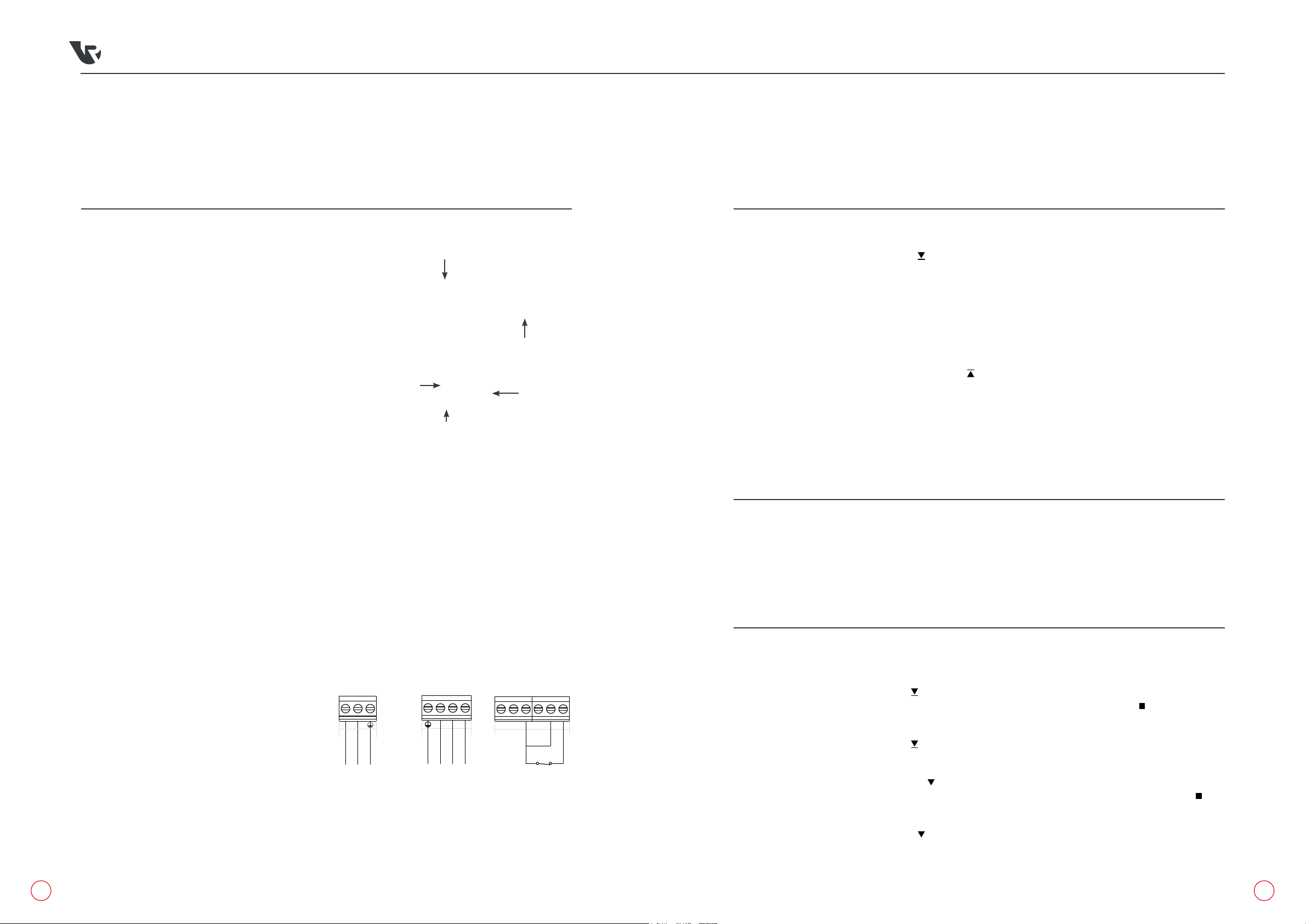
5 Wiring as follows (fig.6.2 & fig.6.3);
Pre wired Mains Power:
N– Neutral / Blue power cable
L– Live / Brown power cable
Earth – Earth power cable
Motor:
L– Brown motor cable (4 core)
R– Black motor cable (4 core)
Earth – Earth connection motor cable
(4 core)
N– Blue motor cable (4 core)
Special Attention: red link wire from
G to U and G to S MUST STAY IN
fig.6.1
fig.6.2
fig.6.3
A
230v TUBE MOTOR
CONNECTION
Connect tube motor
where shown
Note: This connection will supply
230v AC and is specifically for
tube motor operation
Tube Motor 230v AC 50Hz
Mains Supply
230v AC 50Hz
Stop
Gn/Yl
Brown
Blue
Mains Supply Connection
AC IN
N L
Connect mains
power supply
where shown
Recommended
Power Supply
Protection:-
13A fused Spur or
Single Pole
connected
protected by MCB
Type 'A'
Ext Key-Switch Connection
Close
Open
Com
Ext Push Button Connection
Open
Close
L
R
N
Motor Direction
Motor Earth
Motor Common
Motor Direction
Terminal Connections
U D G VU S
MANUAL PHOTOCELL
24v dc
Reflective
Photocell
0v
U D G V U S
MANUAL PHOTOCELL
24v DC Photocell Connection
+24v
N/C
com
UD G VUS
MANUA PHOTOCELL
N
LMains Power 230v AC (Live)
Mains Power 230v AC (Neutral)
Mains Power (Earth)
UExternal connection - Open
D External connection - Close
V +24v dc
G 0V / Switch Common / Photocell Common
Photocell connection - N/C contact
External connection - Stop
Mains Supply
Motor
Manual
Photocell
Basic Remote Control Operation
UDGVUS
MANUAL PHOTOCELL
External
Push Button
Connection
Safety Brake Connection
U D GVU S
MANUAL PHOTOCELL
Safety Brake
(N/C) Switch
Connection
MOTOR
L R N
230v Tube Motor Connection
Gn/Yl
Black
Brown
Blue
Connect tube
motor where
shown
Note:
This connection
will supply 230v
AC and is
specifically
for tube motor
operation
Tube Motor
230v AC 50Hz
MOTOR
L R
Volt free Switching Connection
N
Connection to
provide a 'volt
free' switching
operation
Com
Close
Open
To add an additional external
push button station
Connect where shown leaving link
fitted between G + U
To add an additional external
key-switch
Connect where shown leaving link
fitted between G + U + S
To add an additional photocell for
safety
Connect where shown leaving
links fitted between G + S
Activating the photocell will stop
and re-open a closing door
External
Key switch
Connection
Date
Drawn by
Chk'd by
Drg #
Title
Ellard House
Floats Road
Roundthorn Industrial Estate
Wythenshawe, Manchester
M23 9WB
Tel: 0161 945 4561
Fax: 0161 945 4566
This drawing is the property of ELLARD LTD, it may not be reproduced without the written authorisation of Ellard Ltimited. All interlecual property rights are expressly reserved Revision / Notes:
04/07/2018
D. England
J. Monks
This is a special connection that
does not provide a voltage output
The unit must be factory modified
to give this function and will be
marked 'Volt Free' as such
For Basic remote Control
Operation
Leave links fitted between
G + U + S
Connect safety brake where
shown
Leave link fitted between
U + S
Connection Detail For
ATHENA 2nd GEN
(White Enclosure/White Transmitter)
elec-ATHENA2-001A
Com
MAINS SUPPLY
CONNECTION
Connect mains power supply
where shown
Recommended Power Supply
Protection:- 13A fused Spur or
Single Pole connected protected
by MCB Type 'A'
Mains Supply 230v AC 50Hz
Mains Supply
230v AC 50Hz
Stop
Gn/Yl
Brown
Blue
AC IN
N L
Connect mains
power supply
where shown
Recommended
Power Supply
Protection:-
13A fused Spur or
Single Pole
connected
protected by MCB
Type 'A'
Ext Key-Switch Connection
Close
Open
Com
Ext Push Button Connection
Open
Close
L
R
N
Motor Direction
Motor Earth
Motor Common
Motor Direction
Terminal Connections
U D G VU S
MANUAL PHOTOCELL
24v dc
Reflective
Photocell
0v
U D G V U S
MANUAL PHOTOCELL
24v DC Photocell Connection
+24v
N/C
com
UD G VUS
MANUA PHOTOCELL
N
LMains Power 230v AC (Live)
Mains Power 230v AC (Neutral)
Mains Power (Earth)
UExternal connection - Open
D External connection - Close
V +24v dc
G 0V / Switch Common / Photocell Common
Photocell connection - N/C contact
External connection - Stop
Mains Supply
Motor
Manual
Photocell
Basic Remote Control Operation
UDGVUS
MANUAL PHOTOCELL
External
Push Button
Connection
Safety Brake Connection
U D GVU S
MANUAL PHOTOCELL
Safety Brake
(N/C) Switch
Connection
MOTOR
L R N
230v Tube Motor Connection
Gn/Yl
Black
Brown
Blue
Connect tube
motor where
shown
Note:
This connection
will supply 230v
AC and is
specifically
for tube motor
operation
Tube Motor
230v AC 50Hz
MOTOR
L R
Volt free Switching Connection
N
Connection to
provide a 'volt
free' switching
operation
Com
Close
Open
To add an additional external
push button station
Connect where shown leaving link
fitted between G + U
To add an additional external
key-switch
Connect where shown leaving link
fitted between G + U + S
To add an additional photocell for
safety
Connect where shown leaving
links fitted between G + S
Activating the photocell will stop
and re-open a closing door
External
Key switch
Connection
Date
Drawn by
Chk'd by
Drg #
Title
Ellard House
Floats Road
Roundthorn Industrial Estate
Wythenshawe, Manchester
M23 9WB
Tel: 0161 945 4561
Fax: 0161 945 4566
This drawing is the property of ELLARD LTD, it may not be reproduced without the written authorisation of Ellard Ltimited. All interlecual property rights are expressly reserved Revision / Notes:
04/07/2018
D. England
J. Monks
This is a special connection that
does not provide a voltage output
The unit must be factory modified
to give this function and will be
marked 'Volt Free' as such
For Basic remote Control
Operation
Leave links fitted between
G + U + S
Connect safety brake where
shown
Leave link fitted between
U + S
Connection Detail For
ATHENA 2nd GEN
(White Enclosure/White Transmitter)
elec-ATHENA2-001A
Com
SAFETY BREAK
CONNECTION
Connect safety brake
where shown
Safety Break (N/C) Switch
Connection
Mains Supply
230v AC 50Hz
Stop
Gn/Yl
Brown
Blue
Mains Supply Connection
AC IN
N L
Connect mains
power supply
where shown
Recommended
Power Supply
Protection:-
13A fused Spur or
Single Pole
connected
protected by MCB
Type 'A'
Ext Key-Switch Connection
Close
Open
Com
Ext Push Button Connection
Open
Close
L
R
N
Motor Direction
Motor Earth
Motor Common
Motor Direction
Terminal Connections
U D G VU S
MANUAL PHOTOCELL
24v dc
Reflective
Photocell
0v
U D G V U S
MANUAL PHOTOCELL
24v DC Photocell Connection
+24v
N/C
com
UD G VUS
MANUA PHOTOCELL
N
LMains Power 230v AC (Live)
Mains Power 230v AC (Neutral)
Mains Power (Earth)
UExternal connection - Open
D External connection - Close
V +24v dc
G 0V / Switch Common / Photocell Common
Photocell connection - N/C contact
External connection - Stop
Mains Supply
Motor
Manual
Photocell
Basic Remote Control Operation
UDGVUS
MANUAL PHOTOCELL
External
Push Button
Connection
Safety Brake Connection
U D GVU S
MANUAL PHOTOCELL
Safety Brake
(N/C) Switch
Connection
MOTOR
L R N
230v Tube Motor Connection
Gn/Yl
Black
Brown
Blue
Connect tube
motor where
shown
Note:
This connection
will supply 230v
AC and is
specifically
for tube motor
operation
Tube Motor
230v AC 50Hz
MOTOR
L R
Volt free Switching Connection
N
Connection to
provide a 'volt
free' switching
operation
Com
Close
Open
To add an additional external
push button station
Connect where shown leaving link
fitted between G + U
To add an additional external
key-switch
Connect where shown leaving link
fitted between G + U + S
To add an additional photocell for
safety
Connect where shown leaving
links fitted between G + S
Activating the photocell will stop
and re-open a closing door
External
Key switch
Connection
Date
Drawn by
Chk'd by
Drg #
Title
Ellard House
Floats Road
Roundthorn Industrial Estate
Wythenshawe, Manchester
M23 9WB
Tel: 0161 945 4561
Fax: 0161 945 4566
This drawing is the property of ELLARD LTD, it may not be reproduced without the written authorisation of Ellard Ltimited. All interlecual property rights are expressly reserved Revision / Notes:
04/07/2018
D. England
J. Monks
This is a special connection that
does not provide a voltage output
The unit must be factory modified
to give this function and will be
marked 'Volt Free' as such
For Basic remote Control
Operation
Leave links fitted between
G + U + S
Connect safety brake where
shown
Leave link fitted between
U + S
Connection Detail For
ATHENA 2nd GEN
(White Enclosure/White Transmitter)
elec-ATHENA2-001A
Com
DIRECTION OF ROTATION (HOLD TO RUN)
1 Press and hold the bottom button ( ) on the handset and the barrel should start turning in the downwards
direction. Should the barrel be turning in the up direction, press the middle stop button ( ) so the barrel
stops and then move the le of the three dip switches up (fig.7.2A).
2 Press and hold the bottom button ( ) on the handset, and the barrel should start turning in the downwards
direction.
3 Press and hold the right-hand button ( ) on the front of the receiver box and the barrel should start turning
in the downwards direction. Should the barrel be turning in the up direction, press the middle button ( )
on the front of the receiver box so the barrel stops and then move the right of the three dip switches up (fig.7.2C).
4 Press and release the down button ( ). If the door closes, press the stop button and flick the middle dip
switch up (fig.7.2 B). You should now have to press and hold the down button for the door to close.
B
B
D
C
A
1 Re-attach the front box cable to the board.
2 Press and hold the bottom button ( ), if the door
moves then the handset is already programmed in.
Repeat with all other handsets.
3 If not programmed then press and release the black
programming button located at the top of the receiver
box (fig.7.2). The green LED on the front cover will
start flashing.
4 Press and hold the top button on the handset ( ).
The green LED will flash faster and go out.
5 Test handset by pressing either direction, the barrel
should move. Repeat with all other handsets that
need programming.
fig.7.1
fig.7.2
A B C
DELETING REMOTE CONTROL HANDSET’S MEMORY
1 Press and hold the black programming button for roughly 3 seconds. The green LED will flash three times,
go solid, then rapidly flash. Keep hold until flashing stops.
2 Test to see if remote operates door.