Ropeflex ORYX RX2500 Installation guide

PLEASE REGISTER YOUR NEW PRODUCT
To register your product online please go to:
www.hipeq.com/product-registration
Product serial number is located on equipment or is shown in the box below
SERIAL NUMBER
If serial number is not sown
please check equipment
ORYX –RX2500
Assembly Instructions & Manual
DOC: 32-1016
Configuration subject to change

R X 2 5 0 0 A S S E M B L Y I N S T R U C T I O N S & M A N U A L 32- 0 0 1 6 R E V . B
1
WARNING DECAL PLACEMENT
The decals shown here have been placed on
the equipment in indicated locations. If any of
the decals are missing or illegible, call us toll-
free at 650.549.5888, Monday through Friday,
9 a.m. until 5 p.m. Pacific Time, to order
replacement decals. Apply replacement decals
in the locations shown.
Adjustable Pulley

R X 2 5 0 0 A S S E M B L Y I N S T R U C T I O N S & M A N U A L 32- 0 0 1 6 R E V . B
2
IMPORTANT PRECAUTIONS
WARNING: To reduce the risk of serious injury, read the following important precautions
before using this equipment.
1. Read all instructions in this manual and
assemble as described before using this
equipment.
2. It is the responsibility of the owner to ensure
that all users of this equipment are
adequately informed of all precautions.
3. Use this equipment only on a level surface.
Cover the floor beneath to protect the
surface.
4. Keep children under 12 and pets away from
the equipment at all times.
5. Make sure all parts are properly tightened
each time you use this machine. Replace
any worn parts immediately.
6. Make sure the adjustment knobs are fully
engaged / disengaged before using the
equipment.
7. Always wear athletic shoes for foot
protection while exercising.
8. This equipment is designed to support a
maximum user weight of 300 pounds.
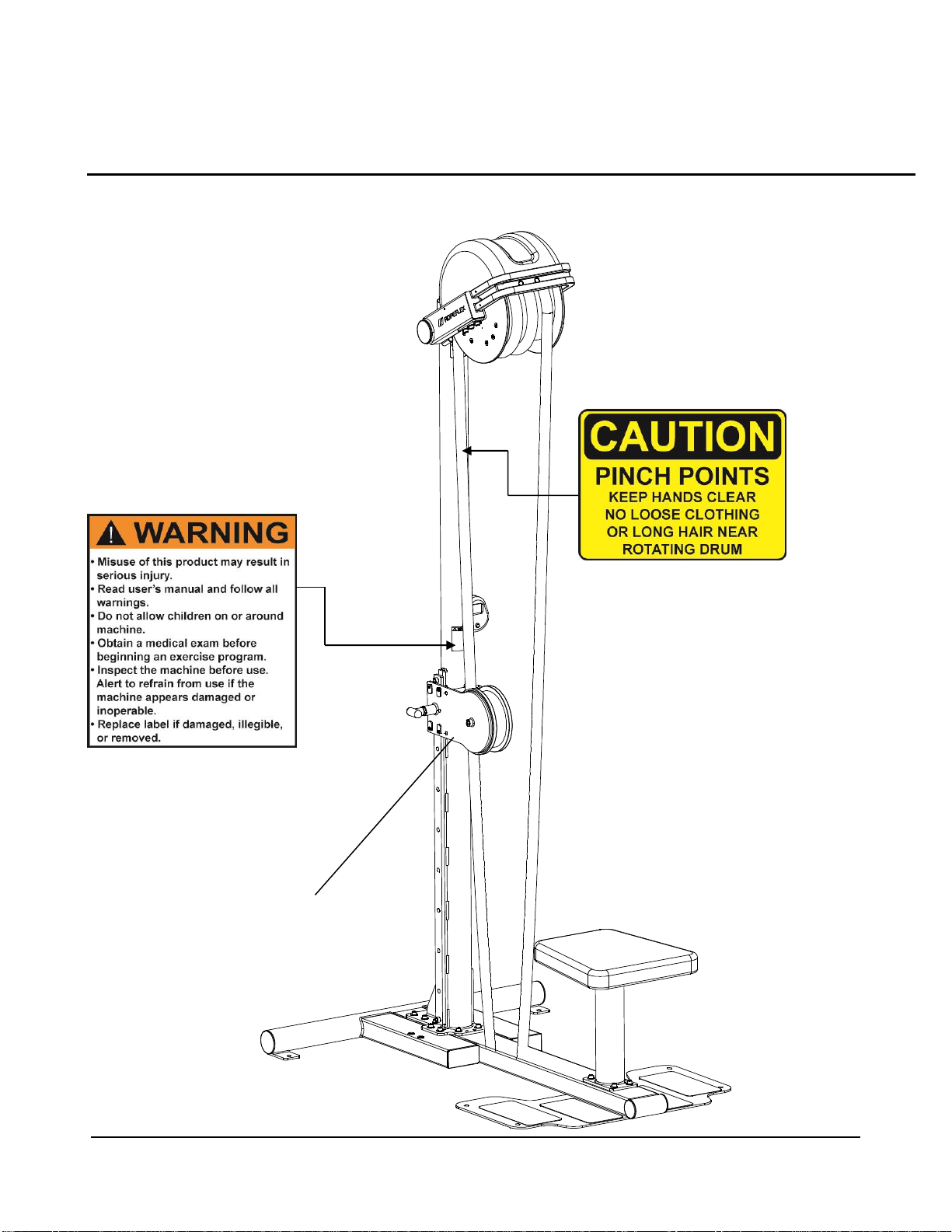
9. Pull on one the rope only and never grab a
rope in a way that prevents the drum from
rotating. Never attempt to hang on the rope.
Pull rope with hands only.
10. If you feel pain or dizziness at any time
while exercising, stop immediately and
begin cooling down.
WARNING: Before beginning this or any exercise program, consult your physician. This is
especially important for persons over the age of 35 or persons with pre-
existing health problems. Read all instructions before using. HIPEQ assumes
no responsibility for personal injury or property damage sustained by or
through the use of this product.

R X 2 5 0 0 A S S E M B L Y I N S T R U C T I O N S & M A N U A L 32- 0 0 1 6 R E V . B
3
Contents / Parts List
ITEM
QUANTITY
DESCRIPTION
1
1
RX2500 Drum with Rope
2
1
RX2500 Main Mast
3
1
RX2500 Base
4
1
RX2500 Seat
5
1
RX2500 Seat stand
6
1
Rope Pulley Assembly
7
24
Button Head Screw 5/16”-18 x 1”
8
24
Washer 5/16”
9
2
Socket Screw 7/16”-14 x 5/8”
10
2
Washer 7/16”
11
1
Display bracket
12
1
LCD Display
13
1
LCD Display screw

R X 2 5 0 0 A S S E M B L Y I N S T R U C T I O N S & M A N U A L 32-001 6 R E V . B
4
Tools Required for Assembly
•3/8 Hex Key for 7/6” Screw
•3/16 or 1/4 Hex Key for 5/16” Button
•5/16 Hex Key for 3/8” Socket Head Screws
Philips #2 Screw Driver

R X 2 5 0 0 A S S E M B L Y I N S T R U C T I O N S & M A N U A L 32-001 6 R E V . B
5
Product Assembly
STEP 1 (Standard RX2500 Configuration)
Parts:
•RX2500 Seat stand
•RX2500 Seat
Hardware:
•Button Head Screw 5/16” x 1”
•Washer 5/16”
Tools:
•3/16 or 1/4 Hex Key for 5/16” Button Head Screws
1-1 Attach RX2500 Seat support plate to RX2500 Seat stand.
1-2 Install and completely tighten hardware (use screw only).
1-3 Attach item from step 1-2 to ORYX Seat (Box 2).
1-4 Install and completely tighten hardware (use screw & washer).
ORYX Seat
ORYX Seat Stand
Hardware (washer)
Qty.4
Hardware (screw)
Qty.8

R X 2 5 0 0 A S S E M B L Y I N S T R U C T I O N S & M A N U A L 32-001 6 R E V . B
6
Product Assembly
STEP 2 (for Hipervision enabled RX2500 refer to page 11)
Parts:
•RX2500 Main Mast
•RX2500 Base
•RX2500 Seat Assembly
Hardware:
•Button Head Screw 5/16” x 1”
•Washer 5/16”
Tools:
•3/16 or 1/4 Hex Key for 5/16” Button Head Screws
2-1 Attach RX2500 Main Mast to Base as shown and completely tighten
hardware (use screws and washers).
2-2 Attach RX2500 Seat Assembly to RX2500 Base as shown and completely
tighten hardware (use screws and washers).
Screw 5/16”
Washer 5/16”
RX2500 Main Mast
RX2500 Seat Assembly

R X 2 5 0 0 A S S E M B L Y I N S T R U C T I O N S & M A N U A L 32-001 6 R E V . B
7
Product Assembly
STEP 3
Parts:
•Assembly from STEP 2
•RX2500 Rope Drum
Hardware:
•Button Head Screw 5/16” x 1”
•Washer 5/16”
Tools:
•3/16 or 1/4 Hex Key for 5/16” Button Head Screws
3-1 Tilt assembly from STEP 2 and lay it down as shown.
3-2 Attach RX2500 Rope Drum to assembly from STEP 2 and completely
tighten hardware on both sides (use screws and washers).
3-3 Attach sensor cable from the Drum to the connector on the RX2500 Main
Mast. Ensure full insertion, most of the time a “click” will be heart and felt.
3-4 Tilt machine back up to a standing position.
Screw 5/16”
Washer 5/16”
Connect sensor
cable

R X 2 5 0 0 A S S E M B L Y I N S T R U C T I O N S & M A N U A L 32-001 6 R E V . B
8
Product Assembly –Pulley Assembly (Revision A)
STEP 4.A
Parts:
•Assembly from STEP 3
•RX2500 Pulley Assembly
Hardware:
•Button Head Screw 7/16” x 5/8”
•Washer 7/16”
Tools:
•3/8 Hex Key for 7/16” Socket Screws
4-1 Attach Pulley Assembly to assembly from STEP 3 and completely
tighten hardware (use screws and washers).
4-2 Attach optional pulley assemblies along the mast, removing filler set screws
as required.
Pulley Assembly
Optional Pulley
Assembly
Screw 5/16”
Washer 5/16”

R X 2 5 0 0 A S S E M B L Y I N S T R U C T I O N S & M A N U A L 32-001 6 R E V . B
9
Product Assembly –Pulley Assembly (Revision B)
STEP 4.B
Parts:
•Assembly from STEP 3
•RX2500 Pulley Assembly REV.B
Hardware:
•Socket Head Screw 3/8-16 or
5/16-18
Tools:
•5/16 Hex Key for 3/8” Socket Head Screws or
•3/16 or 1/4 Hex Key for 5/16” Button
4-3 Attach Pulley Assembly REV B. to assembly from STEP 3 by sliding it from
top of the rail as shown below. Use pull pin to fix pulley in different positions.
4-4 Install “stop screw”as shown and tighten it with an appropriate hex key
Adjustable Pulley
Pull Pin
Stop Screw

R X 2 5 0 0 A S S E M B L Y I N S T R U C T I O N S & M A N U A L 32-001 6 R E V . B
10
Product Assembly –LCD Display (not applicable on Hipervision models)
STEP 5
Parts:
•Assembly from STEP 4
•Display Bracket
•LCD Display
Hardware:
•Button Head Screw 5/16” x 1”
•Washer 5/16”
•Thread Forming #4-20 Screw
Tools:
•3/16 or 1/4 Hex Key for 5/16” Button Head Screws
•Philips #2 Screw Driver
5-1 Attach Display Bracket as shown and tighten hardware
(use screws and washers).
5-2 Remove bottom screw from LCD display, mount display on bracket and
install Thread Forming #4-20 Screw.
Do not over-tighten screw to avoid stripping newly formed plastic threads
5-3 Attach sensor connector from RX2500 Mast to newly installed LCD Display.
Screw 5/16”
Screw 5/16”
Connect sensor cable

R X 2 5 0 0 A S S E M B L Y I N S T R U C T I O N S & M A N U A L 32-001 6 R E V . B
11
Product Assembly - Hipervision enabled RX2500
If the RX2500 was purchased with the Hipervision Bluetooth module please
review the following installation procedure while performing STEP 2 on page 6
Note: Hipervision App is required to establish connection with the Bluetooth
module.
Connections:
•3.5mm mono male to female connector
•On some models a USB socket will be installed on the base and a USB
Type- A connector will be routed through the main mast. This connection
is used to power up smart that are mounted permanently on equipment.
Once connected and additional USB Type-A connector can be found
tucked inside the base for connection to external power supply.
Tools:
•3/16 or 1/4 Hex Key for 5/16” Button Head Screws
•9/64 Hex key for #8-32 battery cover screws
RX2500 Main Mast
Bluetooth module cover
Sensor cables & connectors
RX2500 Base

R X 2 5 0 0 A S S E M B L Y I N S T R U C T I O N S & M A N U A L 32-001 6 R E V . B
12
STEP 2.1
2.1-1 Connect male sensor cable connector to female receptacle on the RX2500
base. Ensure good connection. Electrical tape may be used but is not
required to prevent connectors from separating.
2.1-2 If power cable for smart device is present, insert USB male connector into
USB female panel receptacle located on the base.
2.1-3 Assemble main mast as shown and secure it with screws.
2.1-4 Battery cover is secured by 2 screws. RX2500 ships with batteries
preinstalled. Remove cover only to replace batteries.

R X 2 5 0 0 A S S E M B L Y I N S T R U C T I O N S & M A N U A L 32-001 6 R E V . B
13
Troubleshooting Connection
Go through the following steps if connection with the Bluetooth Hipervision module cannot be
established or if there are any other cable related issues:
1. Refer to illustration below and ensure that batteries are properly inserted and good electrical
contact is established. Check voltage on each battery and replace all if voltage on any one
battery is below 1.3 Vdc
2. Check all sensor connector to ensure proper fitting
a. Refer to Page 7 and Pages 11-12 for external sensor connectors
b. Check sensor cables and connections inside the main vertical mast. If they need to be
pulled out attach a feeding sting to one end in order to route it back.
c. Refer to illustration below to check connection from Bluetooth module to external base
sensor connector. Ensure that the power connector identified by Arrow is fully
inserted into the edge socket. Check cable for damage. 3.5mm sensor cable
connector(s) should be fully inserted into sockets. Note: socket connector identified by
Dashed Arrow is not a sensor socket and is used for daisy chaining multiple units.
3. Perform continuity test on sensor cabling network with the main drum sensor connector
disconnected. Refer to Page 7
4. Perform a separate continuity test on main drum Page 7 by disconnecting cables, connecting
continuity tester to the female 3.5mm connector and manually turning the drum 1 full
revolution. Ensure that there are 4 closed connections per revolution.
5. USE EXTREME CARE WHEN PERFORMING THIS STEP
Remove drum from head frame and disconnect internal sensor cable. Perform a separate
continuity test described in Step 4 and check frame extension cable for damage and
continuity.

R X 2 5 0 0 A S S E M B L Y I N S T R U C T I O N S & M A N U A L 32-001 6 R E V . B
14
Equipment Maintenance
WARNING: Routine inspection and maintenance is of critical importance to ensure
maximum safety and performance. We use the highest quality materials available, but
wear is inevitable. Be advised that dangerous conditions can arise even during a
warranty period. A warranty does not negate the owner’s responsibility to thoroughly,
carefully and daily inspect the machine. Consult your physician before starting your
exercise program. For your own safety, do not begin any exercise program without
proper instruction.
1. Check Rope
While the machine is not in use carefully inspect the rope for damage and tears.
Carefully inspect connection of rope ends and make sure that stitching (threads) are
not torn or damaged. Do not use equipment until damaged rope has been replaced.
2. Upholstery
Wipe down after every workout.
Periodically take the time to use a mild soap or mild vinyl upholstery cleaner. Avoid
using any abrasive cleaner not intended for use on vinyl.
Keep sharp or pointed objects out of your pockets and clear of all upholstery.
3. Nuts/Bolts/Fasteners
Periodically inspect all nuts and bolts. Tighten if needed. If bolts seem to loosen
periodically, use Loctite 242 for a long-term cure.
Go through a re-tightening sequence periodically to ensure that all hardware is
properly tensioned.
4. Adjustments / Locking Pins / Tightening Knobs
Check all pieces for signs of visible wear or damage.
Check springs in Snap Links and Pop Pins for proper tension and alignment.
If the spring sticks or has lost its rigidity, replace it immediately.
5. Anti-Skid Surfaces
Replace if they appear worn or become slippery.
7. Warning Instruction Labels
Inspect and familiarize yourself with all safety warnings and other user information on
decals. Replace decals if damaged, illegible, or removed.

R X 2 5 0 0 A S S E M B L Y I N S T R U C T I O N S & M A N U A L 32-001 6 R E V . A
15
WARRANTY
We strive to offer the simplest and fastest resolution to all product related concerns. Our
warranty service program gives its customers the option to return the product for repair,
exchange or refund if the product is determined to be defective.
•All products are warranted to the original purchaser and must be
registered to receive coverage.
•Warranties apply and cover all defects in material and workmanship.
WARRANTY
Frame (not coatings)
10 years
Structural parts
10 years
Pulleys
5 years
Bearings
5 years
Labor
1 year
Electronics
1 year
Rope / Upholstery
6 months
Accessories
6 months
•Customer is responsible for the cost of shipment to HIPEQ. Company
“ship to” address for product returns and service will be provided once the
RMA has been issued. It will be at HIPEQ’s discretion to determine the
party responsible for cost of shipment back to customer.
•Out-of-Warranty Products are repaired only with the customer’s prior
approval. If you have any questions regarding HIPEQ equipment or any
instruction found in this document, please call 650.549.5888 for
assistance.

16
If you have any questions regarding HIPEQ
equipment or any instruction found in this document,
please call 650.549.5888 for assistance.
HIPEQ
Table of contents
Other Ropeflex Fitness Equipment manuals

Ropeflex
Ropeflex RX2300 Installation guide

Ropeflex
Ropeflex GLADIATOR Installation guide

Ropeflex
Ropeflex APEX-RX4400 Installation guide

Ropeflex
Ropeflex WOLF-RX2200 Operating manual

Ropeflex
Ropeflex IBEX-RX2300 Installation guide

Ropeflex
Ropeflex RXB2 User manual

Ropeflex
Ropeflex VORTEX RX3300 Installation guide

Ropeflex
Ropeflex OX-RX2000 Installation guide

Ropeflex
Ropeflex OX2 User manual

Ropeflex
Ropeflex DRAGON RX1500 Installation guide