Ropox Vario User manual

Ropox Vario
User manual
This manual should always be in close proximity of the
product.
TF 200.01.0050 / Date 27-09-2022

TF 200.01.0050_ENG
2
Table of content
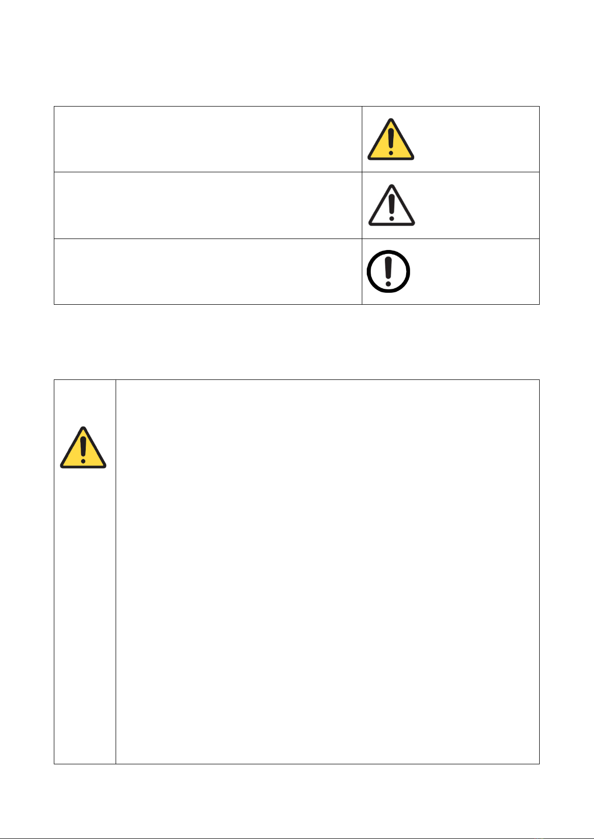
1. Symbols used in this manual.................................................................................................................. 4
2. General safety........................................................................................................................................... 4
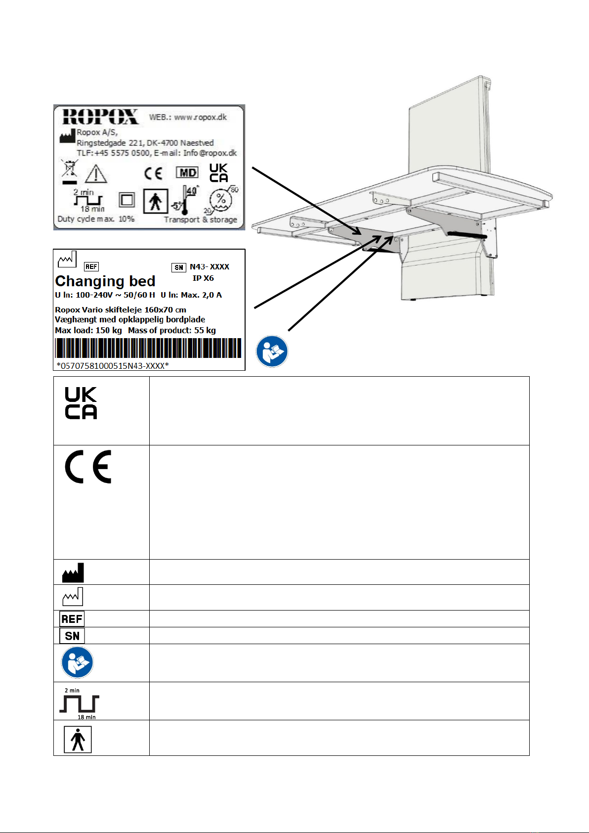
2.1 Product Unit label ........................................................................................................................ 6
3. General requirements .............................................................................................................................. 7
3.1 Product information ......................................................................................................................... 7
3.2 Product description ......................................................................................................................... 8
3.3 Intended purpose ............................................................................................................................ 8
3.4 Intended operator............................................................................................................................ 8
3.5 Essential performance .................................................................................................................... 9
3.6 Complaints and adverse events...................................................................................................... 9
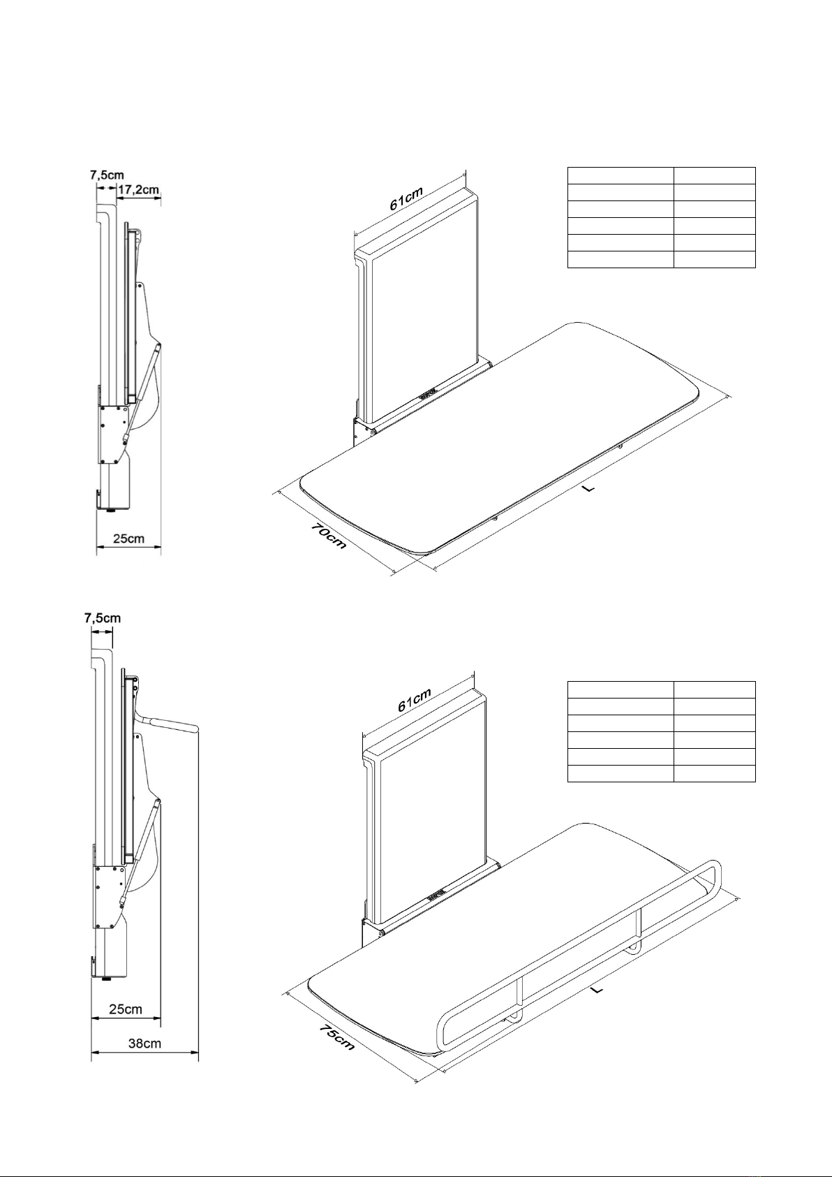
3.7 Product dimensions....................................................................................................................... 10
3.7.1 Without bed guard .................................................................................................................. 10
3.7.2 With bed guard ....................................................................................................................... 10
4. Instructions for use................................................................................................................................ 11
4.1 Installation of product................................................................................................................. 11
4.1.1 Placement of power socket outside of lifting unit ................................................................... 11
4.1.2 Placement of power socket behind lifting unit ........................................................................ 11
4.1.3 Receiving the Changing Bed.................................................................................................. 12
4.1.4 Remove the cover .................................................................................................................. 12
4.1.5 Mounting to the wall................................................................................................................ 13
4.1.6 Mounting the wires ................................................................................................................. 14
4.1.7 Re-mount the plastic cover..................................................................................................... 15
4.1.8 Mount the Tabletop on the Lifting unit.................................................................................... 16
4.1.9 Mount the middle cover plate ................................................................................................. 17
4.2 Operating the product ................................................................................................................ 18
4.2.1 Actuation of the product.......................................................................................................... 18
4.2.2 Operation of the bed guards................................................................................................... 19
4.2.3 How to fold changing bed up and down ................................................................................. 20
4.3 Electrical component diagram ................................................................................................... 21
4.3.1 Wire diagram .......................................................................................................................... 21
4.3.2 Connecting cables.................................................................................................................. 22
4.3.3 Placement of the hand control................................................................................................ 22
4.4 Residual risk .............................................................................................................................. 23
5. Trouble shooting .................................................................................................................................... 24
6. Maintenance............................................................................................................................................ 24
6.1 Periodic maintenance ................................................................................................................ 24
7. Cleaning .................................................................................................................................................. 25
8. Environmental protection...................................................................................................................... 25
9. Spare parts.............................................................................................................................................. 26
10. Accessories ............................................................................................................................................ 27

TF 200.01.0050_ENG
3
10.1 Bed guard................................................................................................................................. 27
10.2 Cushion for bed guard.............................................................................................................. 27
10.3 Mattress ................................................................................................................................... 27
11. Electromagnetic compatibility .............................................................................................................. 28
11.1 Suitable Environments........................................................................................................... 28
11.2 Basic safety and Essential performance ............................................................................... 28
11.3 Adjacent and stacked use...................................................................................................... 28
11.4 Cables.................................................................................................................................... 28

TF 200.01.0050_ENG
4
1. Symbols used in this manual
Warning Symbol
Indication of potentially hazardous situation. If not avoided it can
result in serious injury or death.
Caution Symbol
Indication of potentially hazardous situation which may result in
minor or moderate injury.
It may also be used to alert against unsafe practices.
Notification Symbol
This symbol is used to notify correct use and handling of the
product.
2. General safety
This manual must be read and understood before use. Always
keep this manual in close proximity of the product.
The use, installation and service of this product must be in
compliance with this manual to avoid accidents and serious
personal injury.
Never use or handle this product in other ways specified in
this manual as it can result in personal safety hazards and/or
cause damage to the product.
Persons installing and/or using this product either as operator
or user should have the necessary safety information and
access to this manual.
If the supply cord is damaged, it must be replaced by the
manufacturer, its service agent or similarly qualified
designated persons in order to avoid a hazard.

TF 200.01.0050_ENG
5
Do not perform repairs, disassembly or assembly operations,
add-ons, re-adjustments or modification of the product beyond
what is described in this manual. These must be carried out
by Ropox or Ropox authorized personnel. Do not perform
service while in use.
This appliance can be used by adults who have read and
understood the user manual. Children shall not play with the
appliance.
Cleaning and user maintenance shall not be made by children
without supervision.
Do not use the product if it has defects or have become
damaged before being repaired or replaced.
If the control box makes unusual noise or smells, switch off
the mains voltage immediately.
Take care that the cables are not damaged.
The products must only be used in an environment that
corresponds to their IP protection.
The information in this manual is based on correct installation
in accordance with installation instructions for this product.
Ropox cannot be held liable if the product is used in any way
that differs from stated in this manual and/or installation
instruction.
Ropox reserve the right to amend this manual and reference
documents without prior notice.

TF 200.01.0050_ENG
6
2.1 Product Unit label
This product is UKCA-marked in accordance with:
UK SI 2002 No. 618 - The Medical Devices Regulations 2002, and its amendments
UK SI 2008 No. 1597 - The Supply of Machinery (Safety) Regulations 2008, and its
amendments
This product is CE-marked in accordance with:
European Medical Device Directive 93/42/EEC, including
amendments incorporated in Directive 2007/47/EEC.
European Medical Device Regulation (EU)2017/745
Council Directive 2006/42/EC on machinery
Council Directive 2011/65/EU, RoHS
Manufacturer name and address
Date of production
Stock number
Serial number
Consult manual before use
Operating interval of electrically operated equipment. The use of electrical
height adjustable equipment can run at maximum 2 minutes, followed by an
18-minute break.
Type BF applied part. The product complies with IEC 60601-1 requirements to
provide protection against electric shock
xxxx-xx
40-306x-x

TF 200.01.0050_ENG
7
3. General requirements
3.1 Product information
Manufacturer:
Ropox A/S
Ringstedgade 221, DK-4700 Naestved
+45 55 75 05 00
Product models
Part number
Model
Configuration
40-30604
40-30606
40-30608
40-30610
40-30611
40-30804
40-30806
40-30808
40-30810
40-30811
Vario 120x70cm
Vario 140x70cm
Vario 160x70cm
Vario 180x70cm
Vario 190x70cm
Vario 120x70cm
Vario 140x70cm
Vario 160x70cm
Vario 180x70cm
Vario 190x70cm
With bed guard
With bed guard
With bed guard
With bed guard
With bed guard
Expected service life
5 years
MDD Class
93/68/EEC
MDR Class
2017/745
Class I
Applied part
classification
60601-1
Type BF applied part
MEE Class
60601-1
Class II
Intended environments
This product is to be used only in:
Proffesional Healtcare Environment
Homecare Environment
The device is not intended for use in special environments as defined by IEC
60601-1-2
Maximum user weight
according to DS/EN
ISO 12182:2012
200kg
Power supply
100-240V ~50/60Hz
I in
Max 2.0A
Intermittence
2min use / 18min pause
Consult manual for important safety related information, warnings and safety
precautions.
Class II, double isolated electrical components.
Do not dispose as unsorted municipal waste. Product must be returned to a
designated recycling station.
Operating and storing temperatures may not exceed 5-40C°

TF 200.01.0050_ENG
8
Height adjustment
30-100cm
Speed of actuation
≈17 mm/s
IP rating
IPX6
Ambient temperature
-10 °C to +50 °C Transport and storage
+5 °C to +40 °C Operation
Materials in contact
with patient
Component
Material description
Unit Cover
Tabletop surface
Mattress (accessories)
Bed guards
(accessories)
Lifting unit
ABS
Compact laminate surface.
Dahlia fabric
Backing: 100% polyester
Coating: 100% Polyurethane
ISO 10993-10 Non-Allergic
St37 tube construction with powder coating.
Aluminum anodized with powder coating
Accessories
Item Number
Component
Model/Specification
40-25760-1
40-25795-1
40-25796-1
40-25764-1
40-25765-1
Matresses
For L= 120cm
For L= 140cm
For L= 160cm
For L= 180cm
For L= 190cm
40-30196-1
40-30197-1
Bed guards
For L=120cm, 140cm
For L=160cm, 180cm, 190cm
40-25782-1
40-25783-1
Cushion for bed guard
For L=120cm, 140cm
For L=160cm, 180cm, 190cm
3.2 Product description
Vario is a fixed, height adjustable & foldable changing bed that can be used for care of children and adults up
to 200kg
3.3 Intended purpose
The changing bed is intended for use in private homes, institutions, day care centers and similar institutions
and for people with physical or mental disabilities. The product is designed to provide optimum working
conditions for caregivers. The changing bed can be used in both dry and wet rooms (conditions) but must not
be used as a shower bed.
The height of tabletop (changing bed) can be adjusted from 30-100 cm using the hand control and can be
folded up for space saving when not in use.
3.4 Intended operator
Reading and understanding this manual will be sufficient training for an intended operator. Children and
patients are not considered intended operator.

TF 200.01.0050_ENG
9
3.5 Essential performance
The device does not have any function related to basic safety or essential performance. In case of loss or
degradation of performance, the user can be lifted off the device
3.6 Complaints and adverse events
Any serious incident that has occurred in relation to the device should be reported to the manufacturer and the
competent authority of the Member State in which the user and/or patient is located.

TF 200.01.0050_ENG
10
3.7 Product dimensions
3.7.1 Without bed guard
3.7.2 With bed guard
Model
Length (L)
40-30604
120cm
40-30606
140cm
40-30608
160cm
40-30610
180cm
40-30611
190cm
Model
Length (L)
40-30804
120cm
40-30806
140cm
40-30808
160cm
40-30810
180cm
40-30811
190cm

TF 200.01.0050_ENG
11
4. Instructions for use
4.1 Installation of product
4.1.1 Placement of power socket outside of lifting unit
The main power cable
has a total length of
approx. 320cm of which
250cm is outside the
lifting unit. The cable can
be pulled out in either left
or right side.
4.1.2 Placement of power socket behind lifting unit
The following drawing illustrates the space that can be
allocated for an electrical outlet without interfering with the
movement of the unit. The blue-hatched area is the safe area
for placing an electrical outlet and cover. Placing the outlet
and/or cover outside of this area may result in product damage
and malfunction.
If possible, hold off on the final position of the mains cable and
cover in the wall, until the lifting unit has been fully placed and
fixed to the wall (steps for mounting the unit are detailed later in
this manual). Then raise the sled to the top-level position and
use the cutout to ensure a safe fit of the electrical cable and
cover with proper clearance all around.
Note: Depth of electrical outlet (incl. wire) must not exceed
65mm from the wall

TF 200.01.0050_ENG
12
Caution!
If you have other objects mounted right next to this changing bed, you have to consider the
risk of trapping, and therefore consider a safe distance to the other objects.
4.1.3 Receiving the Changing Bed
The Ropox Vario Changing Bed will come in two packages. One for the “Lifting unit” and one for the
“tabletop”.
4.1.4 Remove the cover
The plastic cover can slide up and released from the lifting unit, or it can be clicked out by pulling it forward.
!! Take care not to scratch the plastic cover in the process !!
Tabletop
Lifting unit with cover
Middle Cover Plate

TF 200.01.0050_ENG
13
4.1.5 Mounting to the wall
Place the lifting unit in the desired location. Be especially aware of any
items on the floor and wall that might be in the way of the product
during it’s full movement (30-100cm from the floor)
Attach the frame securely to the wall by using adequate bolts and
rawlplugs suitable for the type of wall construction / material on site.
The changing bed is supplied with a set (7 pcs) of screws and
rawlplugs, which are ONLY intended for mounting the unit in a concrete
wall. If the unit is to be mounted on another kind of wall, suitable plugs
and screws for that wall type must be used. The Ropox Changing bed
is tested according to a load of up to 200kg applied to the changing
bed.
The attachment holes can be marked up on the wall, four possibilities in
the top, and three in the bottom of the frame. Place the frame against
the wall and make sure it is horizontal. The frame is standing on two
adjustable feet. Adjust these if the floor is uneven or has a tilt, until the
top of the lifting unit is level. Mark out the hole locations. Remove the
frame and drill the holes.
Maximum pull force for each of the four
screws in top of the unit: 40kg
Note!
Make sure that no dust or other obstacles are interfering with the rollers, chain, sprocket, or
gas springs. This can cause malfunction and damage the system.
Caution!
It is important that the frame is screwed securely to the wall. If the frame comes loose, a
person may fall off the changing bed.

TF 200.01.0050_ENG
14
To gain access to all the bottom holes, the
control box will need to be temporarily
removed. This is done by unlocking it from
the holder at the top, pressing it back and
sliding the control box down.
Remember to securely re-attach the
controlbox, before putting the cover back
on the lifting unit.
4.1.6 Mounting the wires
If the electrical outlet is placed behind the unit, It is
crucial to control the cable from the outlet, down to the
control box. This is to ensure that the sled will not
squeese, cut or otherwise damage the cable during
product use.
Fix the mains cable to the brackets (highlighted by the
arrows) using the included zip-ties, making sure the
cable is tight with no loose parts that could get trapped
by the moving sled.
Once everything is placed, perform a test-run of the
full length of travel down and up again to ensure that
nothing is in danger of entrapment or collides with the
moving sled.

TF 200.01.0050_ENG
15
4.1.7 Re-mount the plastic cover
The cover can either be clicked in place from the front or slide down from
above. Make sure that the cover reaches the floor and is in contact with the
wall at the top. This step can also wait until the end of the installation process
if ease of access to the electrical components is required.
When all the wires have been attached and
screws fastened, the cover must be fixed in
place. Use the attached M5x8 screws and
screw button cover. This step can wait until the
end to make it easier to access the control box
and wires if needed.
Once the screw is tightened, click on the white
button plastic cover.

TF 200.01.0050_ENG
16
4.1.8 Mount the Tabletop on the Lifting unit
Slide the tabletop in between the
lifting unit and the support arms
on the lifting unit. It is an
advantage to be two persons
when doing this.
Fasten the tabletop to the Lifting
unit with 4 pcs. M8x12 through
the bushings in the support arms.

TF 200.01.0050_ENG
17
4.1.9 Mount the middle cover plate
If the large plastic cover has not
yet been installed, do this
before starting this step.
Set the middle plate against the
plastic cover at an angle, as
shown.
Rotate the cover into place
Push it down until you hear the
locks snap into place
Double check that it sits flush
and fiirmly on the lifting unit

TF 200.01.0050_ENG
18
4.2 Operating the product
Before starting use of this product, be sure that “main power” has been connected as described in
electrical connections.
4.2.1 Actuation of the product
The product is operated with the spiral cord hand control. Arrow up will move the product upwards, and arrow
down will move the product downwards.
Warning!
The product should always be able to travel the full range of actuation without colliding
with objects. Failing to do so will compromise the product stability.
Special care should be taken in ensuring that no children or adults are sited under the
product as severe injury from entrapment may occur.
Warning!
Before use always make sure that mains cable and hand control cable will be able to travel
freely without the risk of squeezing or disconnecting the product as result of the movement.
•After mounting, with the cover off, make sure that the chain is in correct
position on the sprocket, also check that cable plugs are connected correctly to
the control box.
•Check that no cables can be trapped or squeezed during the full range of
movement of the product
•Connect the main power, and the changing table is ready to be used.

TF 200.01.0050_ENG
19
Warning!
The product should always be able to travel the full range of actuation without colliding with
objects. Failing to do so will compromise the product stability.
Special care should be taken in ensuring that no children or adults are sited under the
product as severer injury from entrapment may occur.
Only adjust the product in height position, when the table-top is in horizontal position
Note!
The control buttons are «push and hold». Height adjustment stops as soon as the button is
released. This is an important safety measure.
4.2.2 Operation of the bed guards
Vario is not supplied with bed guard as standard. This can be ordered as an accessory.
To operate the bed guards, pull the rubber tubing placed under the tabletop to release the locking mechanism.
The bed guard can then be pivoted to the desired mode.
Warning!
Make sure that the bed guard is locked securely in place when in use. Locking is checked
by shaking the bed guard back and forth ensuring that the locking pin is fully engaged.

TF 200.01.0050_ENG
20
4.2.3 How to fold changing bed up and down
The changing bed can be secured against inadvertent folding while in the upright position by locking the table
with the locking pin.
When worktop is folded up, press and hold the red button while inserting the split. The changing bed is now
locked against folding down. Verify that the lock is engaged by pulling the worktop.
For folding changing bed in downwards position, remove locking pin by pressing and holding the red button,
while removing the split. The top can now be lowered by hand.
Note!
Prior to folding worktop in upright position, bed guard must be turned underneath worktop.
Warning!
Always make sure worktop is securely locked in upright position with locking pin when left in
this position. Check changing table is locked by pulling the worktop to ensure locking pin is
fully engaged and worktop cannot be lowered.
Warning!
NEVER leave a person on the changing bed unattended - not even for a very
short period.
If two changing beds are mounted next to each other, it’s recommended to mount a
side cover between, to avoid the trapping risk.
Other manuals for Vario
1
Table of contents
Other Ropox Medical Equipment manuals
Popular Medical Equipment manuals by other brands

Halyard
Halyard INDISCAL Instructions for use

PULOX
PULOX PO-300 instruction manual

Abilia
Abilia Lightwriter SL50 user manual

Haws
Haws 7500EB Installation, operation & maintenance instructions

Tuffcare
Tuffcare Century Max T5248 Operation manual

Given Imaging
Given Imaging SmartPill GI Monitoring System user manual