Ropox Mobilio Series User manual

Ropox Mobilio Shower bed
User manual
This manual should always be in close proximity of the
product.
PDF6217 / Rev002

PDF6217 / Rev002
2
Table of content
1. Symbols used in this manual.................................................................................................................. 4
2. General safety........................................................................................................................................... 4
2.1 Product label.............................................................................................................................. 5
3. General requirements .............................................................................................................................. 6
3.1 Product information....................................................................................................................... 6
3.2 Intended use.................................................................................................................................. 7
3.3 Intended operator.......................................................................................................................... 7
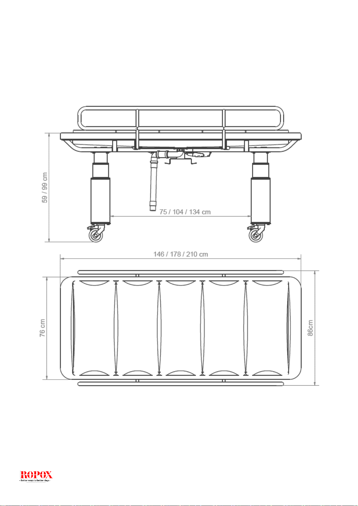
3.4 Dimensions.................................................................................................................................... 8
4. Instructions for use.................................................................................................................................. 9
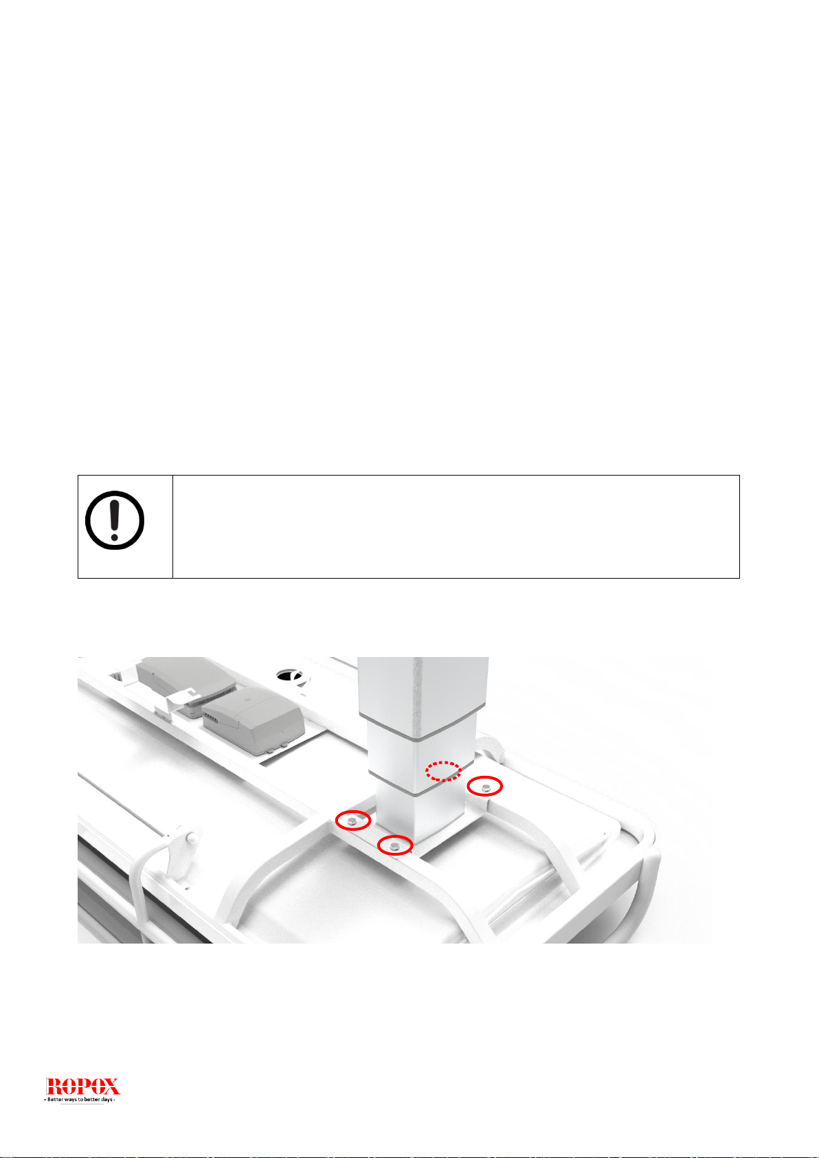
4.1 Product assembly ...................................................................................................................... 9
4.1.1 Assembly of legs .................................................................................................................... 9
4.1.2 Connection of wires in the controlbox .................................................................................. 10
4.2 Operating the product.............................................................................................................. 11
4.2.1 Actuation of the product........................................................................................................ 11
4.2.2 Activation and release of brake systems.............................................................................. 12
4.2.3 Operation of the bed guards................................................................................................. 12
4.3 Installation of battery................................................................................................................ 13
4.3.1 Mounting the battery............................................................................................................. 13
4.3.2 Connecting the battery ......................................................................................................... 13
4.3.3 Charging the battery............................................................................................................. 14
4.3.4 Battery feedback indicators.................................................................................................. 14
4.4 Electric block diagram.............................................................................................................. 14
5. Cleaning .................................................................................................................................................. 15
6. Maintenance............................................................................................................................................ 15
6.1 Periodic maintenance of bed guards....................................................................................... 15
6.2 Periodic charging of battery..................................................................................................... 15
6.3 Replacement of battery............................................................................................................ 16
6.4 Fault finding ............................................................................................................................. 16
6.5 Calibration of lifting columns.................................................................................................... 16
7. Environmental protection...................................................................................................................... 16
8. Accessories ............................................................................................................................................ 17
8.1 Battery...................................................................................................................................... 17
8.2 Cushion for bed guards ........................................................................................................... 17
8.5 Central brake system............................................................................................................... 18
9. Electro magnetic compability ............................................................................................................... 18
9.1 Suitable Environments............................................................................................................. 18
9.2 Basic safety and Essential performance ................................................................................. 18
9.3 Adjacent and stacked use........................................................................................................ 18
9.4 Cables...................................................................................................................................... 19
9.5 RF portable equipment ............................................................................................................ 19
9.6 Compliance for emission and immunity standard.................................................................... 19
9.6.1 Emission class and group..................................................................................................... 19

PDF6217 / Rev002
4
1. Symbols used in this manual
Warning Symbol
Indication of potentially hazardous situation. If not avoided it can
result in serious injury or death.
Caution Symbol
Indication of potentially hazardous situation which may result in
minor or moderate injury.
It may also be used to alert against unsafe practices.
Notification Symbol
This symbol is used to notify correct use and handling of the
product.
2. General safety
This manual must be read and understood before use. Always keep this manual in close
proximity of the product.
The use, installation and service of this product must be in compliance with this manual to
avoid accidents and serious personal injury.
Never use or handle this product in other ways specified in this manual as it can result in
personal safety hazards and/or cause damage to the product.
Persons installing and/or are using this product either as operator or patient should have the
necessary safety information and access to this manual.
Always comply with instructions in this manual to avoid damaging or destroying the product.
Not doing so can cause the safety of this product to be compromised.
Do not perform repairs, disassembly or assembly operations, add-ons, re-adjustments or
modification of the product beyond what is described in this manual. These must be carried
out by Ropox or Ropox authorized personnel. Do not perform service while in use with a
patient.
Do not allow children to operate this product unless they are under supervision from an
adult that has read and understood this manual. The product is not intended to play with.
Do not use the product if it has defects or have become damaged before being repaired or
replaced.
The information in this manual is based on correct installation in accordance with installation
instructions for this product.
Ropox cannot be held liable if the product is used in any way that differs from stated in this
manual and/or installation instruction.
Ropox reserve the right to amend this manual and reference documents without prior notice.

PDF6217 / Rev002
5
2.1 Product label
This product is CE-marked in accordance with the
Regulation (EU) 2017/745
Council Directive 2006/42/EC
Council Directive 2011/65/EU
Manufacturer name and address
Date of production
Stock number
Serial number
Consult manual before use
Operating interval of electrically operated equipment. The use of electrical
height adjustable equipment can run at maximum 2 minutes, followed by an
18-minute break.
Type B applied part. The product complies with IEC 60601-1 requirements
to provide protection against electric shock.
Consult manual for important safety related information, warnings and safety
precautions.
Class II, double isolated electrical components.
Do not dispose as unsorted municipal waste. Product must be returned to a
designated recycling station.
Mobile phones or other portable RF emitting equipment should be no closer
to the product than 30cm.
Operating and storing temperatures may not exceed 5-40C°

PDF6217 / Rev002
6
3. General requirements
3.1 Product information
Manufacturer:
Product models
Part number
Model
Configuration
40-31406-1
40-31410-1
40-31411-1
Mobilio Shower Bed 148x76cm
Mobilio Shower Bed 178x76cm
Mobilio Shower Bed 210x76cm
Standard lockable
wheels
MDR Class
(EU) 2017/745
Class I
Applied part classification
60601-1
Type B applied part
MEE Class
60601-1
Class II
Height adjustment
59-99cm
Speed of actuation
≈18mm/s
Maximum user weight
according to
EN12182:2012
200kg
Power supply
100-240V ~50/60Hz
I in
Max 2.0A
Intermittence
2min use / 18min pause
IP rating
IPX6
Ambient temperature
5-40C° Operation and storage
Materials in contact with
patient
Tub
Cushion for bed guard
Bed guard
Slats
ABS/PMMA
Dahlia fabric
Backing: 100% polyester
Coating: 100% Polyurethane
ISO 10993-10 Non Allergic
St37 tube steel, powder coated
PUR FLEX 200
Intended environments
This product is to be used only in:
Proffesional Healtcare Environment
Homecare Environment
The device is not intended for use in special environments as defined by IEC
60601-1-2
Accessories
BA19 Lead acid battery
40-30762
Specification
• Lead acid technology: Lead acid
• Output voltage: 24 V DC
• Max. discharge current: 6 A
• Charging current: 300 mA, controlled by BA19
internal charger
• Capacity: 1.2 Ah / 28.8 Wh
• Weight: 1.6 kg
Usage

PDF6217 / Rev002
7
Cushion for bed guard
40-25782-1
40-25783-1
Central brake system
40-30753-2
40-30760-2
40-30763-2
• Compatibility: Battery backup for CA30/CA40 and
CO61
• Duty cycle: 10%, 2 minutes continuous use followed
by 18 minutes not in use
• Charging: Via integrated charger
• Charging time: Approx. 6 hours
• Recharging during storage: Battery recharging no
later than 6 months after production date stated on
the label
• Operating temperature: +5°C to +40°C
• Storage temperature: -5°C to +40°C
The batteries must be stored in an applicable storage
room to avoid direct sunlight
• Relative humidity: 20% to 80%, but non-condensing
acc. to temp.
• Atmospheric pressure: 700 to 1060 hPa
• Service: Battery cells cannot be replaced as the
battery cover cannot be closed properly afterwards
For L= 148cm
For L= 178cm, 210cm
For L= 148cm
For L= 178cm
For L= 210cm
3.2 Intended use
The mobile height adjustable shower bed can be used to nurse children and adults up to 200 kg.
The shower bed is intended for use in private homes, day-care centers, day centers for persons
with physical or mental disabilities, or similar institutions, to provide the right and optimal working
conditions for the staff. The mobile shower bed can be used in both dry and wet rooms. The
shower bed is freestanding, mobile and with brake wheels to ensure optimum working conditions.
The height of the work surface can be adjusted step less from 59-92´9 cm using a spiral cord
handset.
3.3 Intended operator
Reading and understanding this manual will be sufficient training for an intended operator. Children
nor patient are not considered intended operator.

PDF6217 / Rev002
8
3.4 Dimensions

PDF6217 / Rev002
9
4. Instructions for use
4.1 Product assembly
4.1.1 Assembly of legs
Mount the legs with 8x enclosed M8 bolts. I is recommended to cross tighten the 4 bolts, on each leg
assembly.
Notification!
Remember to use locking shims! All bolts are tightened with a torque of 12Nm / 8.9ft/lbs

PDF6217 / Rev002
10
4.1.2 Connection of wires in the controlbox
Wires are connected according to picture and designation shown below.
Notification!
All wires are sealed with O-rings, make sure these a fully engaged by pushing the
connectors firmly to the bottom of the socket.
A
Motor cable 1
B
Motor cable 2
C
Handset
D
Battery (accessorie)

PDF6217 / Rev002
11
4.2 Operating the product
Warning!
Before use always make sure that mains cable and hand control cable will be able to
travel freely without the risk of squeezing or disconnecting the product as result of the
movement.
Caution!
When connected to the mains the product must be placed in a manner according to
power outlets so that the operator will be able to disconnect the product during use in
case of an emergency.
4.2.1 Actuation of the product
The product is operated with the spiral cord hand control. Arrow up will move the product upwards
and arrow down will move the product downwards.
Warning!
The product should always be able to travel the full range of actuation without colliding
with objects. Failing to do so will compromise the product stability.
Special care should be taken in ensuring that no children or adults are sited under the
product as severer injury from entrapment may occur.

PDF6217 / Rev002
12
4.2.2 Activation and release of brake systems
To activate the brake wheels use appropriated foot pad.
Caution!
The central brake system or standard locking brakes must always be locked and secure
before a patient is placed on the product.
The product is not intended as a mean for patient transportation and the use of it must only
be stationary.
4.2.3 Operation of the bed guards
To operate the bed guards pull the rubber tubing placed under the table top to release the locking
mechanism. The bed guard can then be pivoted to the desired mode.
Warning!
Make sure that the bed guard is locked securely in place when in use. Locking is
checked by shaking the bed guard back and forth ensuring that the locking pin is
fully engaged.
Central locking
wheels
(accessories)

PDF6217 / Rev002
13
4.3 Installation of battery
Mobilio is not supplied with a backup battery. This can be ordered as an accessory. To order a battery
use the following part number: 40-30762
Notefication!
The installation of the battery must be in compliance with the following installation guide
4.3.1 Mounting the battery
4.3.2 Connecting the battery
•Stop actuation of lifting coloumns
•Switch of the controlbox by disconnecting the mains plug.
•Connect the battery to the port in the controlbox.
BA19 battery
CO61 control box

PDF6217 / Rev002
14
4.3.3 Charging the battery
The battery will automatically charge through an integrated charger when the product is connected to the
mains. A full charging takes approx 6 hours and is indicated through the LED on the battery
Notefication!
Before using the battery the first time make sure to charge it for 24hours. This will prolong
the life of the battery.
4.3.4 Battery feedback indicators
The battery has a built in buzzer that automatically gives feedback to the user when the capacity is low. This
will sound when the product is operated with the hand control for adjusting the height.
4.4 Electric block diagram
Caution!
Check battery capacity before use if the battery is the only power source. Make sure that the
product is within distance of a power outlet to ensure continous function of the product when
used wih a patient in case the battery become exhausted.
Battery (accessories)
lifting
column
Control box
Hand control
Power
100-240V AC
lifting
column

PDF6217 / Rev002
15
5. Cleaning
Cleaning can be done with lukewarm water and a suitable all purpose cleaning agent. Use a cloth or soft
sponge to wash the product. Dry the product of with a wrung cloth.
Cleaning of slats
Lime deposits on slats are removed with a household bathroom cleaning agents
Chemical resistance
Detergents containing the following chemicals must not be used for cleaning:
Acetone
Ammonium carbonate
Ethyl acetate
Formic acid
Hydrochloric acid
Isopropanol
Methyl acetate
Nitric acid
Phosphoric acid
Notification!
Do not use cleaning agents containing abrasive e.g. scouring powder, steel wool, scouring
sponge.
This product is not designed to be sterilized, autoclaving and sterilization beyond normal
cleaning is may possibly change the product safety and function.
6. Maintenance
Notification!
Failing to comply with periodic maintenance may result of degrading of product function and
safety.
6.1 Periodic maintenance of bed guards
If the product is used humid or dry atmosphere the locking pin may be prone to seizing from lubricants
drying. Besides checking the function of the locking mechanism before every use, a periodic lubrication
of the locking pin every 6 month is recommended.
6.2 Periodic charging of battery
The battery must be periodically charged minimum every 6 months to sustain capacity. If the product is
left unused or the battery is disconnected this may result degrading of the battery capacity. Charging the
battery minimum every 6 months will mitigate this.

PDF6217 / Rev002
16
6.3 Replacement of battery
Notefication!
The battery are to be replaced after 4 years at the latest.
6.4 Fault finding
6.5 Calibration of lifting columns
Lifting columns are aligned and calibrated from the factory. In case they need calibration to run
simultaneously use the “Reset” procedure.
7. Environmental protection
The product is not intended to be disposed as municipal waste. Proper disassembly, sorting and
disposal of components must be done by waste disposal professionals.
Part
Disposal recommendation
Tub
Hard plastic
Slats
Soft plastic
Bed guards
Steel waste
Frame and wheel assemlby
Steel waste
Controlbox
Electronics
Lifting columns
Aluminimum or electronic waste
BA19 batteri
Lead acid battery waste
Problem
Tjek følgende:
Mobilio does not move up or down when the hand-
control switch is pressed
1. The product is connected to 230V and the
control box LED indicator lights green
2. Motor cables are connected to control box
3. The control switch has been connected with
the control unit
4. If the product is used with battery, check
whether it is charged.
5. The motors are overloaded (note: 2 min.
ON, 18 min OFF).
Control switch defective
1. Mobilio works with another control switch
Mobilio is not horizontal / level
”Reset”
Press and hold UP ( ) and DOWN ( ) buttons.
Keep the buttons depressed until the control unit
has beeped approx.. ten times. After that, the
bathtub may be adjusted to the bottom position for
resetting.
1.

PDF6217 / Rev002
17
8. Accessories
8.1 Battery
Mobilio can be powered by a backup battery which can be ordered separately. Always follow the
instructions for proper use and installation, see 4.3.
Item number: 40-30762-2
8.2 Cushion for bed guards
Item nr.
Size
Pcs.
40-25782-1
L= 148cm
1
40-25783-1
L= 178, 210cm
1

PDF6217 / Rev002
18
8.5 Central brake system
Item nr.
Size
Pcs
40-30753-2
L= 148cm
1
40-30760-2
L= 178cm
1
40-30763-2
L= 210cm
1
9. Electro magnetic compability
9.1 Suitable Environments
The device is suitable for use at home, at daycare centres, at day centres for persons with
physical or mental disabilities or at hospitals except near active HF surgical equipment and
the RF shielded room of an medical electrical system for magnetic resonance imaging,
where the intensity of electromagnetic disturbances is high.
9.2 Basic safety and Essential performance
The device does not have any function related to basic safety or essential performance. In
case of loss or degradation of performance, the user can get on and off the product.
9.3 Adjacent and stacked use
Warning !
Use of this equipment adjacent to or stacked with other equipment should be
voided because it could result in improper operation. If such use is necessary,
this equipment and the other equipment should be observed to verify that they
are operating normally

PDF6217 / Rev002
19
9.4 Cables
Cable component
Length
Power cable
3,2m
Hand control spiral cable
Approx. 5m extended.
Warning!
Use of accessories, transducers and cables other than those specified or
provided by the manufacturer of this could result in increased electromagnetic
emissions or decreased electromagnetic immunity of this equipment and result in
improper operation.
9.5 RF portable equipment
Warning !
Portable RF communications equipment (including peripherals such as antenna
cables and external antennas) should be used no closer than 30 cm (12 inches)
to any part of the device, including cables specified by the manufacturer.
Otherwise, degradation of the performance of this equipment could result.
9.6 Compliance for emission and immunity standard
The product is tested and found compliant for EMC according to EN60601-1-2:2015 for Clause 7 and
Clause 8. Documentation are tested and found compliant according to EN60601-1-2:2015 for Clause 5
9.6.1 Emission class and group
Phenomenon
Test method
Class
Group
Conducted RF emissions
EN 55011
Class B
Group 1
Radiated RF emissions
EN 55011
Class B
Group 1
Harmonic current
emissions
EN 61000-3-2
Class A
-
Voltage changes, voltage
fluctuations and flicker
emissions
EN 61000-3-3
-
-

PDF6217 / Rev002
20
9.6.2 Immunity test levels
Phenomenon
Test method
Immunity test level
Electrostatic discharge
immunity
EN 61000-4-2
+/- 8 kV contact
+/- 2, 4, 8, 15 kV air
Electrostatic discharge
immunity –I/O
SIO/SOP ports
EN 61000-4-2
+/- 8 kV contact,
+/- 2, 4, 8, 15 kV air
Connectors shall be tested.
Do not test pins, as they can not be contacted or touched,
under conditions of intended use.
Radiated RF
electromagnetic field
immunity
EN 61000-4-3
10 V/m 80 MHz to 800 MHz
20 V/m 800 MHz to 2.5 GHz
10 V/m 2.5 GHz to 2.7 GHz
80 % AM 1 kHz
Immunity to proximity
fields from RF wireless
communication
equipment
EN 61000-4-3
385 MHz, 27 V/m, 18 Hz PM (50 % duty cycle square wave)
450 MHz, 28 V/m, FM +/- 5 kHz dev., 1 kHz sine
710 MHz, 9 V/m, 217 Hz PM (50 % duty cycle square wave)
745 MHz, 9 V/m, 217 Hz PM (50 % duty cycle square wave)
780 MHz, 9 V/m, 217 Hz PM (50 % duty cycle square wave)
810 MHz, 28 V/m, 18 Hz PM (50 % duty cycle square wave)
870 MHz, 28 V/m, 18 Hz PM (50 % duty cycle square wave)
930 MHz, 28 V/m, 18 Hz PM (50 % duty cycle square wave)
1720 MHz, 28/ V/m, 217 Hz PM (50 % duty cycle square
wave)
1845 MHz, 28 V/m, 217 Hz PM (50 % duty cycle square wave)
1970 MHz, 28 V/m, 217 Hz PM (50 % duty cycle square wave)
2450 MHz, 28 V/m, 217 Hz PM (50 % duty cycle square wave)
5240 MHz, 9 V/m, 217 Hz PM (50 % duty cycle square wave)
5500 MHz, 9 V/m, 217 Hz PM (50 % duty cycle square wave)
5785 MHz, 9 V/m, 217 Hz PM (50 % duty cycle square wave)
Electrical fast
transient/burst immunity
–AC power ports
EN 61000-4-4
+/- 2 kV
100 kHz repetition frequency
Electrical fast
transient/burst immunity
–I/O SIO/SOP ports
EN 61000-4-4
+/- 1 kV
100 kHz repetition frequency
Surge immunity –AC
power ports
EN 61000-4-5
Line-to-line: +/- 0.5, 1 kV line to line
Line-to-ground: Not applicable, the device is a
Class II device
Immunity to conducted
disturbances induced
by RF fields –AC
power ports
EN 61000-4-6
3 V (6 V in ISM bands and amateur radio bandsa)
0.15-80 MHz
80 % AM 1 kHz
Immunity to conducted
disturbances induced
by RF fields –I/O
SIO/SOP ports
EN 61000-4-6
3 V (6 V in ISM bands and amateur radio bandsa)
0.15-80 MHz
80 % AM 1 kHz
Power frequency
magnetic field immunity
EN 61000-4-8
30 A/m
50 Hz and 60 Hz
Test as tabletop equipment, for at least 1 minute in each
direction
Voltage dips, short
interruptions and
voltage variations
immunity
EN 61000-4-11
0 % UT; 0.5 cycle at 0°, 45°, 90°, 135°, 180°, 225°, 270° and
315°
0 % UT; 1 cycle at 0°
70 % UT; 10 cycles at 0°
0 % UT; 250 cycles at 0°
a) The ISM (industrial, scientific and medical) bands between 0.15 MHz and 80 MHz are 6.765 MHz to 6.795 MHz; 13.553 MHz to
13.567 MHz; 26.957 MHz to 27.283 MHz; and 40.66 MHz to 40.70 MHz. The amateur radio bands between 0.15 MHz and 80 MHz
are 1.8 MHz to 2.0 MHz. 3.5 MHz to 4.0 MHz. 5.3 MHz to 5.4 MHz. 7 MHz to 7.3 MHz. 10.1 MHz to 10.15 MHz. 14 MHz to 14.2 MHz.
18.07 MHz to 18.17 MHz. 21.0 MHz to 21.4 MHz. 24.89 MHz to 24.99 MHz. 28.0 MHz to 29.7 MHz and 50.0 MHz to 54.0 MHz.
This manual suits for next models
4
Table of contents
Other Ropox Medical Equipment manuals
Popular Medical Equipment manuals by other brands

FREEWAY
FREEWAY S180E Mobile Hoist user manual

Hospira
Hospira Sapphire quick start guide

Integra
Integra MAYFIELD A1121 instruction manual

Gynesonics
Gynesonics Sonata System Service manual

DeVilbiss
DeVilbiss DV54 AutoAdjust CPAP Series owner's manual

DeVillbiss Air Power Company
DeVillbiss Air Power Company 525DS Service manual