Ropox 25-20010 User manual

All-in-one hoist 150kg
User manual
This manual should always be in close proximity of the
product.
TF 200.01.0009_eng / Dato 20-04-2022

TF 200.01.0009_eng
2
Table of content
1. Symbols used in this manual.................................................................................................................. 4
2. General safety........................................................................................................................................... 4
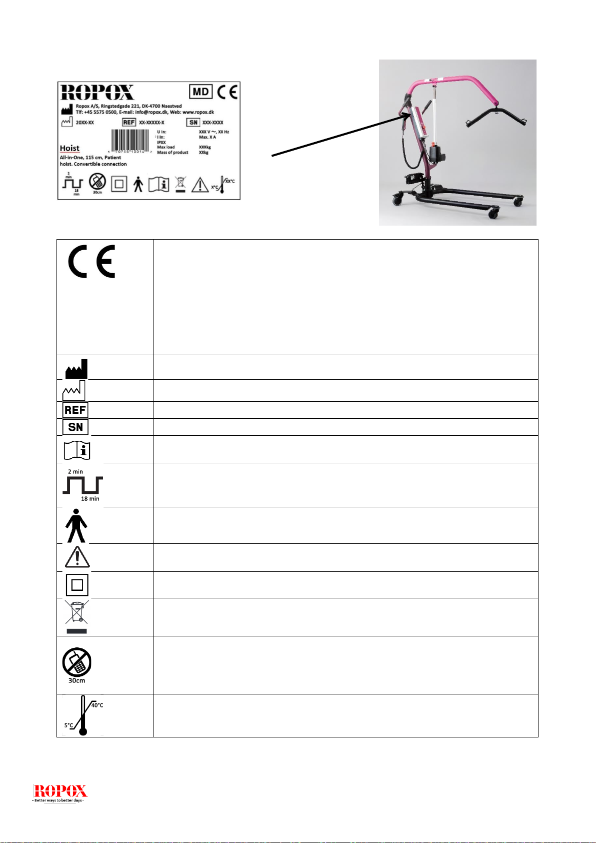
2.1 Product Unit label ...................................................................................................................... 6
3. General requirements .............................................................................................................................. 7
3.1 Product information.................................................................................................................... 7
3.2 Product description.................................................................................................................... 8
3.3 Intended use.............................................................................................................................. 8
3.4 Intended operator ...................................................................................................................... 8
3.5 Essential performance............................................................................................................... 8
3.6 Basic safety................................................................................................................................ 8
3.7 Non clinical functions................................................................................................................. 8
3.8 Product dimensions ................................................................................................................... 9
4. Instructions for use................................................................................................................................ 12
4.1 Assembly instructions.............................................................................................................. 12
4.2 Mounting and dismounting of arm with spreader bar and stand-up hoist module................... 13
4.3 Operating the product.............................................................................................................. 14
4.3.1 Operating instructions........................................................................................................... 14
4.3.2 Emergency situation............................................................................................................. 15
4.4 Recharging the battery ............................................................................................................ 15
4.5 Safety function, liftingmotor ..................................................................................................... 15
4.6 Safety function, control unit ..................................................................................................... 15
4.7 Emergency lowering ................................................................................................................ 16
4.8 Brakes...................................................................................................................................... 16
4.9 Transfer –person lifting........................................................................................................... 17
4.9.1 Lifting from wheelchair.......................................................................................................... 17
4.9.2 Placing in wheelchair............................................................................................................ 17
4.9.3 Lifting to and from bed.......................................................................................................... 18
4.9.4 Lifting from floor.................................................................................................................... 18
4.10 Transfer –Stand-up hoist .................................................................................................... 18
4.10.1 Lifting from chair................................................................................................................. 19
4.11 Installation of accessories.................................................................................................... 20
4.12 Electrical component diagram ............................................................................................. 21
5. Trouble shooting .................................................................................................................................... 22
6. Cleaning .................................................................................................................................................. 23
7. Maintenance............................................................................................................................................ 23
7.1 Periodic maintenance .............................................................................................................. 23
7.2 Daily check............................................................................................................................... 23
7.3 Monthly maintenance............................................................................................................... 24
7.4 Yearly inspection ..................................................................................................................... 24
7.5 Maintenance report mechanical parts ..................................................................................... 25
7.6 Maintenance report actuator/lifting motor................................................................................ 26

TF 200.01.0009_eng
3
7.7 Lifetime of actuator/liftingmotor................................................................................................ 27
8Components part list.............................................................................................................................. 28
8.1 Spare parts .............................................................................................................................. 28
9Environmental protection...................................................................................................................... 29
10. Electro magnetic compability ............................................................................................................... 29
10.1 Suitable Environments......................................................................................................... 29
10.2 Cables.................................................................................................................................. 29
10.3 RF portable equipment........................................................................................................ 29

TF 200.01.0009_eng
4
1. Symbols used in this manual
Warning symbol
Indication of potentially hazardous situation. If not avoided it can
result in serious injury or death.
Caution Symbol
Indication of potentially hazardous situation which may result in
minor or moderate injury.
It may also be used to alert against unsafe practices.
Notification Symbol
This symbol is used to notify correct use and handling of the
product.
2. General safety
This manual must be read and understood before use.
Always keep this manual in close proximity of the product.
The use, installation and service of this product must be in
compliance with this manual to avoid accidents and serious
personal injury.
Never use or handle this product in other ways specified in
this manual as it can result in personal safety hazards and/or
cause damage to the product.
Persons installing and/or using this product either as operator
or user should have the necessary safety information and
access to this manual.
If the supply cord is damaged, it must be replaced by the
manufacturer, its service agent or similarly qualified
designated persons in order to avoid a hazard.

TF 200.01.0009_eng
5
Do not perform repairs, disassembly or assembly operations,
add-ons, re-adjustments or modification of the product
beyond what is described in this manual. These must be
carried out by Ropox or Ropox authorized personnel. Do not
perform service while in use.
This appliance can be used by children aged from 8 years
and above and persons with reduced physical, sensory or
mental capabilities or lack of experience and knowledge if
they have been given supervision or instruction concerning
use of the appliance in a safe way and understand the
hazards involved. Children shall not play with the appliance.
Cleaning and user maintenance shall not be made by
children without supervision.
Do not use the product if it has defects or have become
damaged before being repaired or replaced.
If the control box makes unusual noise or smells, switch off
the mains voltage immediately.
Take care that the cables are not damaged.
Unplug the mains cable on mobile equipment before it is
moved.
The products must only be used in an environment that
corresponds to their IP protection.
The information in this manual is based on correct installation
in accordance with installation instructions for this product.
Ropox cannot be held liable if the product is used in any way
that differs from stated in this manual and/or installation
instruction.
Ropox reserve the right to amend this manual and reference
documents without prior notice.

TF 200.01.0009_eng
6
2.1Product Unit label
This product is CE-marked in accordance with:
European Medical Device Directive 93/42/EEC, including
amendments incorporated in Directive 2007/47/EEC.
European Medical Device Regulation (EU)2017/745
Council Directive 2006/42/EC on machinery
Council Directive 2011/65/EU, RoHS
Manufacturer name and address
Date of production
Stock number
Serial number
Consult manual before use
Operating interval of electrically operated equipment. The use of electrical
height adjustable equipment can run at maximum 2 minutes, followed by an
18-minute break.
Type B applied part. The product complies with IEC 60601-1 requirements to
provide protection against electric shock.
Consult manual for important safety related information, warnings and safety
precautions.
Class II, double isolated electrical components.
Do not dispose as unsorted municipal waste. Product must be returned to a
designated recycling station.
Mobile phones or other portable RF emitting equipment should be no closer
to the product than 30cm.
Operating and storing temperatures may not exceed 5-40C°

TF 200.01.0009_eng
7
3. General requirements
3.1Product information
Manufacturer:
Product models
Part number
Model
Configuration
UDI
25-20010-9
25-20020-9
25-20030-9
25-20040-9
25-20050-9
Patient hoist
Combined
Stand-up hoist
Patient hoist
Stand-up hoist
Konverteringsmulighed
Personløfter/stålift
Konverteringsmulighed
Uden konvertering
Uden konvertering
57075810802S7
57075810800S3
57075810804SB
57075810801S5
57075810803S9
MDD Class
93/68/EEC
MDR Class
2017/745
Class I
Applied part
classification
60601-1
Type B applied part
MEE Class
60601-1
Class II
Intended environments
according to
IEC 60601-1-2
This product is to be used only in:
Proffesional Healtcare Environment
Homecare Environment
The device is not intended for use in special environments as defined by IEC
60601-1-2
Maximum user weight
according to DS/EN ISO
10535:2007
150kg
Power supply
100-240V ~50/60Hz
I in
Max 2.5A
Intermittence
2min brug / 18min pause
Height adjustment
55-180 cm
Speed of actuation
≈15mm/s
IP rating
IPX4
Ambient temperature
range
-5 °C to +40 °C Transport and storage
+5 °C to +40 °C Operation
Relative humidity:
20% to 80% - non-condensing
Materials in contact with
patient
Sling (varianter)
Spreader bar
Polyester
St37 tube construction
with powder coating.

TF 200.01.0009_eng
8
Accessories
Item number
25-20120-9
25-20455-9
25-29950-9
25-29030-9
Model/specification
Stand-up kit 150 kg
Patient hoist kit 150 kg
Wall charging depot incl. battery
Battery
3.2Product description
All in one hoist system is a mobile hoist for people with limited mobility who need help with
relocation. The health personnel can, using different slings, lift people up to 150 kg respectively.
3.3Intended use
The product is used in situations where a patient has to be lifted from one stationary bed to another
stationary bed. The product must not be used for patient transport. The product must always be
used with Ropox suitable lifting slings.
3.4Intended operator
Intended operator must have relevant health professional training before using the product, as well
as have read and understood this guide. Children, patient or lay person is not considered a
suitable operator.
3.5Essential performance
The lifting motor has a mechanical emergency lowering facility. In case of failure of electronics during use,
this can be used to lower the patient to a safe height.
3.6Basic safety
The battery must always be checked for capacity before starting work. An audible warning will
sound if the battery capacity is too low. The product is equipped with an emergency stop, its
function must also be checked before use.
3.7Non clinical functions
The product has no clinical effect. This is a patient lifter.

TF 200.01.0009_eng
9
3.8Product dimensions
25-20010
25-20020
25-20040
Patient hoist
25-20020
25-20030
25-20050
Stand-up hoist
Lifting capacity
150 kg
150 kg
Min. lifting height, lifting hook
55 cm
95 cm
Max. lifting height. lifting hook
180 cm
191 cm
Lifting travel
125 cm
96 cm
Length chassis frame
117 cm
117 cm
Length legs
97 cm
97 cm
Min. inside distance between legs
50 cm
50 cm
Max. inside distance between legs
94 cm
94 cm
Min. outside distance between legs
65 cm
65 cm
Max. outside distance between legs
109 cm
109 cm
Height of chassis frame
12 cm
12 cm
Free height under legs
7 cm
7 cm
Wheel diameter
100/75 cm
100/75 cm
Turning circle
125 cm
125 cm
Weight of arm with spreader bar
6,5 kg
Weight of fork-shaped bar
5,5 kg
Weight of knee support with base plate
8,5 kg
Weight of battery
3,0 kg
3,0 kg
Total weight
51,0 kg
58,5 kg
Approximate number of lifting operations
per charging
Weight of arm with spreader bar
60
60

TF 200.01.0009_eng
10
1980
1225
755
600
590
725
930
410
840
700
530

TF 200.01.0009_eng
11
60
115
520
160
190

TF 200.01.0009_eng
12
4. Instructions for use
4.1Assembly instructions
4.1.1 Place the lifting mast in the mast
holder of the frame. Tighten the
two screws with the 5mm Insex
wrench provided, and use
locking nut on opposite site.
4.1.2 Connect the cable from the leg
spreading motor to the control
unit in output terminal 2, see
“Electrical component diagram”
M6
låsemøtrik
Screws
Locking nut
Screws

TF 200.01.0009_eng
13
4.2Mounting and dismounting of arm with spreader bar and stand-up hoist
module
Mounting
1. Brake the rear wheels.
2. Hold the lifting module (turn it through 90°) so that the locking pin may be pushed into
the corresponding slide rail of the lifting mast.
3. Be aware that the bar may swing. We recommend holding on to it.
4. Push in the lifting module.
5. Then turn it 90° clockwise until you hear a click.
6. Make sure that the arm has been properly locked.
7. If the hoist is going to be used as a stand-up hoist, hook on the knee support with base
plate.
8. Now the hoist is ready for use.
Dismounting
1. Brake the rear wheels.
2. If the hoist has been used as a stand-up hoist, lift off the knee support.
3. Pull the locking pin while turning the lifting module 90° counter-clockwise.
4. Be aware that the bar may swing. We recommend holding on to it.
5. Now the lifting module may be pulled out.

TF 200.01.0009_eng
14
Note! Be aware of the weight of the lifting module.
4.3Operating the product
For the All-in-One you can use any of Ropox Domino slings.
4.3.1 Operating instructions
-Check that the emergency stop has been released. If not, turn the button clockwise until release.
-The hoist is operated by means of the hand control unit. The two upper buttons control the lifting/lowering
movement, whereas the two lower buttons control the leg spreading facility. It is not possible to use two
functions simultaneously.
-Check that the sling provided is correct for the lifting operation to be performed. This applies to size as well
as shape. Further information about the choice of slings will be found in ”Domino Slings User manual”.
-The battery should be recharged regularly, to ensure that the hoist is always available (e.g. every night).
NOTE!
It is important that you are familiar with the use of the hoist and its functions, and that it
works properly. So for the best possible safety, all users of the hoist must read this user
manual before using the hoist.
NOTE!
In case of erroneous operation of the hand control unit (e.g. too quick change of
direction) the hoist does not react. Let go of the push button –wait a few seconds and
press again.
Locking pin

TF 200.01.0009_eng
15
4.3.2 Emergency situation
Emergency stop and emergency lowering (electrical and mechanical) should be used in emergencies only.
Should it be necessary to activate the emergency functions, contact the distributor before using the hoist again.
4.4Recharging the battery
-The battery must be recharged after approx. 60 lifting operations –i.e. at 50% battery capacity. In case of
continued use you will hear an acoustic signal. The battery can still be used, but it will affect is recharging
capability.
-We recommend charging as soon as the hoist is not being used for a longer period of time, e.g. every night.
The battery cannot be over-charged and it is only ”healthy” for the battery to be recharged often as it
increases the battery life.
-Charging is made directly in the control unit by means of the mains cable provided. Insert the cable into the
wall outlet and the control unit, see drawing page 12, and switch on power. The hoist cannot be used when
connected to mains voltage.
-A green light on the control unit indicates connection to mains voltage. A yellow light indicates that the
battery is being recharged.
-When the battery has been fully charged, the yellow light will be out.
-Full recharging takes 4-5 hours.
-If charging is made via a wall-mounted charging station (optional) a battery may be constantly charged in
the station. The batteries may be easily switched by means of the snap system on top of the battery box.
4.5Safety function, liftingmotor
The lifting motor is provided with a safety function, splejn, against jamming. If the lifting arm meets with
resistance during lowering, the movement of the arm will stop automatically. Thus, a person cannot get
jammed between the lifting arm and the bed.
4.6Safety function, control unit
-protective motor switch for lifting and leg spreading, protecting against overloading
-short-circuit protection
-acoustic signal sounding when the batteries need charging
-electrical emergency lowering if the hand control unit does not work
-built-in charger
NOTE!
Make sure that the plug from the battery is correctly inserted in the control box, if the plug
have been pulled out, before using the lift again.

TF 200.01.0009_eng
16
Emergency stop
If the hoist is to be stopped owing to an emergency –press the red button on the control unit. When the
button has been depressed the electrical functions of the hoist cannot be activated and the battery indicator
has been switched off.
4.7Emergency lowering
If the hoist is to be lowered and the hand control unit does not work, there are two possible solutions:
-The electrical emergency lowering of the control unit (marked emergency), see drawing page 21. Press
with a ball pencil or the like and the person will be lowered slowly.
-The mechanical emergency lowering of the lifting motor. Pull up the red handle, see drawing.
4.8Brakes
The hoist may be braked on
the two large rear wheels.
Press down the rear part of the
brake with the foot to brake the
hoist. Release the brake by
pressing the front part of the
brake with the foot.
WARNING!
Owing to the safety function on the motor the lifting arm and spreader bar may fall freely
to the spindle of the motor.
Therefore make sure that the lifting arm does not ”hang”, that is
has always been pressed down to ensure that it rests on the
spindle of the motor before and after all lifting operations. This
is important as otherwise an injury may result if the lifting arm
”falls” down.
NOTE!
Never brake the hoist during lifting except when used in stand-up mode.
Brake
Release
The lifting motor has a mechanical
emergency lowering facility. To release
it, pull the red handle.

TF 200.01.0009_eng
17
4.9Transfer –person lifting
-It is important that the user is familiar with the hoist and that it works satisfactorily before lifting a person.
-It is important to choose the correct type of sling for the lifting operation to be performed. This applies to
size as well as shape. Further information about the choice of sling will be found in ”Instructions for the Use
of Domino Slings”.
-With a person in the hoist always move slowly in order to avoid swaying.
-Only use the hoist on surfaces with less than 5° gradient.
-Only brake the hoist when it is parked or standing on a sloping surface, e.g. in bathrooms.
-Never lift a person higher than necessary.
-Be aware of the maximum load of the hoist.
4.9.1 Lifting from wheelchair
-Mount the sling.
-Increase the width between the legs of the hoist and move it to the chair.
-Place the spreader bar above the person in the chair.
-Lower the lifting arm and place the straps of the sling correctly in the hooks of the spreader bar. Make
sure that all straps have been fitted correctly.
-Lift the person a few centimetres above the seat of the chair - STOP –and make sure that the sling
has been fitted correctly.
-When the person is comfortable in the sling, lift him/her clear of the chair.
-Pull the hoist away from the chair - STOP –adjust the legs of the hoist to parallel position before
proceeding with the transfer.
4.9.2 Placing in wheelchair
To place a person in a wheelchair proceed in reverse order:
-Increase the width between the legs of the hoist and move it to the chair.
-Make sure that the person has been placed correctly in relation to the chair and lower
the hoist slowly.
-Check that the person is in the proper position during the entire operation.
-When assisting a person in getting back into the chair, lower the person to just touch
the chair.
-If the chair can be tilted a little backward it is easier to place the person correctly. Also
pull the straps on the back of the sling.
-If two helpers are available, one may press gently on the knees of the person.
NOTE!
The wheelchair must be braked during transfer to and from the chair.
Be careful that the sling does not jerk or pinch wires attached to the patient.
Before lifting a client, try the hoist yourself.
Risk assessment shall be carried out to ensure that the
correct size, type and shape of slings is being used for
the patient

TF 200.01.0009_eng
18
4.9.3 Lifting to and from bed
-If the bed has an adjustable headrest and the client is capable of being raised a little, a raised
headrest will facilitate application of the sling.
-Place the lower edge of the sling so that it just covers the base of the spine.
-If the client is to be transferred from wheelchair to bed, a raised headrest will also facilitate the
operation. It will be easier to place the client correctly in the bed and to remove the sling straps.
-As an alternative roll the client to a lateral position. Unfold the sling and place it so that the lower
edge just covers the base of the spine.
-Place the spreader bar above the bed and lower it to approx. 25 cm above the waist.
-Fix the straps of the sling in the spreader bar.
-Lift the client slowly approx. 2 cm above the bed and make sure that the sling is positioned correctly
and that the client is comfortable and properly supported.
-Lift the client clear of the bed and transfer him/her to the required position.
4.9.4 Lifting from floor
Make sure that the general condition of the client allows him/her to be lifted.
-Follow the same procedures as when lifting from bed when placing the sling under the client.
-Lift the client to a half seated position and use a chair or a similar stable back support with a cushion.
-Move the open end of the hoist towards the client and lift the legs of the client over one leg of the
hoist. Do not brake the hoist.
-The hoist may be placed in the opposite position, i.e. with the head of the client towards the control
unit of the hoist.
-Lower the lifting arm and fix the straps of the sling in the spreader bar.
-Lift the client slowly while checking that the sling is placed correctly and that the client is comfortable
and properly supported.
4.10 Transfer –Stand-up hoist
-It is important that the user is familiar with the operation of the hoist and that it performs properly prior to
lifting.
-It is important to choose the correct type of sling for the lifting operation to be performed. This applies to
size as well as shape. Further information about the choice of slings will be found in ”Instructions for the
Use of Domino Slings”.
-Transfer of a person in a stand-up hoist must only be made to and from seated
position.
-The stand-up hoist must be braked during lifting.
-The client must not wear slippery clothes or underwear.
-Be aware of the maximum load of the hoist.
NOTE!
Always adjust the sling before lifting the client completely clear of the bed .
The bed must be locked whem moving to and from bed.
Be careful that the sling does not jerk or pinch wires attached to the patient.
NOTE!
When operating the hoist use the wheels opposite to the push handles as a pivot point.
This will facilitate manoeuvring.

TF 200.01.0009_eng
19
4.10.1 Lifting from chair
-Apply the Thorax standing sling with the lower edge right above the waistband.
-Increase the width between the legs of the hoist and move it to the chair.
-Approach the client and place his/her legs on the base plate.
-Push the hoist as closely to the client as possible –brake the hoist.
-Adjust the knee support so that it provides support right under the knees of the client.
-Lower the lifting arm.
-Place the lifting straps of the sling in the hooks of the fork-shaped lifting bar.
-If the client can hold on to the lifting bar with his/her arms during lifting, use the middle step of the
suspension strap.
-If the client has but little stability and strength in the upper part of the body, use the outermost step of
the suspension strap.
-Tell the client to lean back in the sling and look up.
-Now lifting may be commenced. If required, support the client during lifting.
-Lift the client to standing position.
-To prevent the sling from sliding upward, place the straps in a loop.
WARNING!
Make sure that the feet of the client do not get jammed between base plate and floor.
NOTE!
We recommend lifting the client approx. ¾, so that the knees are slightly bent. Be aware
of the pressure on the knees/lower part of the leg.

TF 200.01.0009_eng
20
4.11 Installation of accessories
Mounting of person and stand-up kit
-Brake the rear wheels.
-Hold the lifting module (turn it through 90°) so that the locking pin may be pushed into the corresponding
slide rail of the lifting mast.
-Be aware that the bar may swing. We recommend holding on to it.
-Push in the lifting module.
-Then turn it 90° clockwise until you hear a click.
-Make sure that the arm has been properly locked.
-If the hoist is going to be used as a stand-up hoist, hook on the knee support with base plate.
-Now the hoist is ready for use.
Other manuals for 25-20010
1
This manual suits for next models
4
Table of contents
Other Ropox Medical Equipment manuals
Popular Medical Equipment manuals by other brands

College Park
College Park venture Technical instructions

Invacare
Invacare Freeway Freedom IRC1175 Operator's manual

bort medical
bort medical SellaTex Plus quick guide

St. Jude Medical
St. Jude Medical TactiSys Quartz Equipment user manual

Otto Bock
Otto Bock 1B1-2 Meridium Instructions for use

Dicarre
Dicarre DA09a instructions