Ropox Vario 40-30604 User manual

Ropox Vario
User manual
This manual should always be in close proximity of the
product.
TF 200.01.0018_ENG / 26-07-2022

2
TF 200.01.0018_ENG
Table of content
1. Symbols used in this manual.................................................................................................................. 4
2. General safety........................................................................................................................................... 4
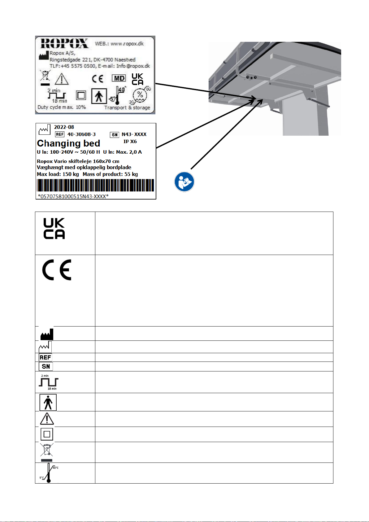
2.1 Product label.............................................................................................................................. 6
3. General requirements .............................................................................................................................. 7
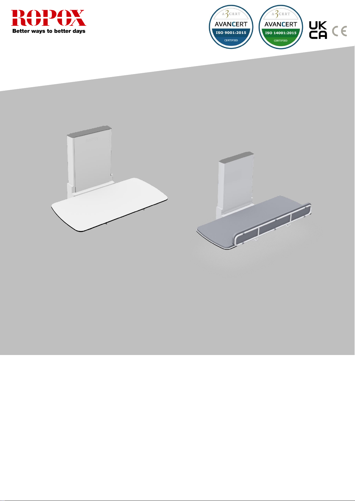
3.1 Product information....................................................................................................................... 7
3.2 Intended use.................................................................................................................................. 8
3.3 Intended operator.......................................................................................................................... 8
3.4 Dimensions.................................................................................................................................... 9
3.4.1 Without bed guard.................................................................................................................. 9
3.4.2 With bed guard ....................................................................................................................... 9
4. Instructions for use................................................................................................................................ 10
4.1 Receiving the Vario changing bed .............................................................................................. 10
4.2 Placement of power socket......................................................................................................... 10
4.2.1 Placement outside of lifting Unit........................................................................................... 10
4.2.2 Placement behind lifting unit ................................................................................................ 11
4.3 Assembly preparations................................................................................................................ 12
4.3.1 Dismount the top cover plate................................................................................................ 12
4.3.2 Dismount the front plate ....................................................................................................... 12
4.4 Mounting to the wall .................................................................................................................... 13
4.4.1 Mount the lifting unit to the wall with screws at the top and bottom..................................... 14
4.4.2 Slide the front plate back into the lifting unit......................................................................... 15
4.4.3 Mount the cover plate on the top of the lifting ...................................................................... 15
4.5 Mount the tabletop on the lifting unit........................................................................................... 16
4.6 Wire diagram............................................................................................................................... 17
4.6.1 Connecting cables................................................................................................................ 18
4.6.2 Placement of the hand control.............................................................................................. 18
5. Instructions for use................................................................................................................................ 19
5.1 Operating the product.............................................................................................................. 19
5.1.1 Actuation of the product........................................................................................................ 19
5.1.2 Operation of the bed guards................................................................................................. 20
5.1.3 How to fold changing bed up and down ............................................................................... 20
5.1.4 Locking of shower bed.......................................................................................................... 21
5.1.5 Unlocking of shower bed...................................................................................................... 21
5.2 Recommendations in use ........................................................................................................ 21
6. Cleaning .................................................................................................................................................. 22
7. Maintenance............................................................................................................................................ 22
7.1 Periodic maintenance of bed guards....................................................................................... 22
7.2 Trouble shooting...................................................................................................................... 22
8. Environmental protection...................................................................................................................... 23
9. Spare parts.............................................................................................................................................. 23
10. Accessories ............................................................................................................................................ 24
10.1 Bed guard.................................................................................................................................. 24
10.2 Cushion for bed guard............................................................................................................... 24

3
TF 200.01.0018_ENG
10.3 Mattress..................................................................................................................................... 24
11. Electromagnetic compatibility .............................................................................................................. 25
11.1 Suitable Environments......................................................................................................... 25
11.2 Basic safety and Essential performance ............................................................................. 25
11.3 Adjacent and stacked use.................................................................................................... 25
11.4 Cables.................................................................................................................................. 25
11.5 RF portable equipment ........................................................................................................ 25
12. Complaints.............................................................................................................................................. 26

4
TF 200.01.0018_ENG
1. Symbols used in this manual
Warning Symbol
Indication of potentially hazardous situation. If not avoided, it can result in serious injury or
death.
Caution Symbol
Indication of potentially hazardous situation which may result in minor or moderate injury.
It may also be used to alert against unsafe practices.
Notification Symbol
This symbol is used to notify correct use and handling of the product.
2. General safety
This manual must be read and understood before use.
Always keep this manual in close proximity of the product.
The use, installation and service of this product must be in
compliance with this manual to avoid accidents and serious
personal injury.
Never use or handle this product in other ways specified in
this manual as it can result in personal safety hazards and/or
cause damage to the product.
Persons installing and/or are using this product either as
operator or patient should have the necessary safety
information and access to this manual.

5
TF 200.01.0018_ENG
Always comply with instructions in this manual to avoid
damaging or destroying the product. Not doing so can cause
the safety of this product to be compromised.
Do not perform repairs, disassembly or assembly operations,
add-ons, re-adjustments or modification of the product
beyond what is described in this manual. These must be
carried out by Ropox or Ropox authorized personnel. Do not
perform service while in use with a patient.
Do not allow children to operate this product unless they are
under supervision from an adult that has read and
understood this manual. The product is not intended to play
with.
Do not use the product if it has defects or have become
damaged before being repaired or replaced.
If the control box makes unusual noise or smells, switch off
the mains voltage immediately.
Take care that the cables are not damaged.
The products must only be used in an environment that
corresponds to their IP protection.
The information in this manual is based on correct installation
in accordance with installation instructions for this product.
Ropox cannot be held liable if the product is used in any way
that differs from stated in this manual and/or installation
instruction.
Ropox reserve the right to amend this manual and reference
documents without prior notice.

6
TF 200.01.0018_ENG
2.1 Product label
This product is UKCA-marked in accordance with:
UK SI 2002 No. 618 - The Medical Devices Regulations 2002, and its amendments
UK SI 2008 No. 1597 - The Supply of Machinery (Safety) Regulations 2008, and its
amendments
This product is CE-marked in accordance with:
European Medical Device Directive 93/42/EEC, including
amendments incorporated in Directive 2007/47/EEC.
European Medical Device Regulation (EU)2017/745
Council Directive 2006/42/EC on machinery
Council Directive 2011/65/EU, RoHS
Manufacturer name and address
Date of production
Stock number
Serial number
Operating interval of electrically operated equipment. The use of electrical height
adjustable equipment can run at maximum 2 minutes, followed by an 18-minute
break.
Type BF applied part. The product complies with IEC 60601-1 requirements to
provide protection against electric shock.
Consult manual for important safety related information, warnings and safety
precautions.
Class II, double isolated electrical components.
Do not dispose as unsorted municipal waste. Product must be returned to a
designated recycling station.
Operating and storing temperatures may not exceed 5-40C°

7
TF 200.01.0018_ENG
3. General requirements
3.1 Product information
Manufacturer
Product models
Part number
Model
Configuration
40-30604
40-30606
40-30608
40-30610
40-30611
40-30804
40-30806
40-30808
40-30810
40-30811
Vario 120x70cm
Vario 140x70cm
Vario 160x70cm
Vario 180x70cm
Vario 190x70cm
Vario 120x70cm
Vario 140x70cm
Vario 160x70cm
Vario 180x70cm
Vario 190x70cm
With bed guard
With bed guard
With bed guard
With bed guard
With bed guard
Expected service life
5 years
MDR Class
(EU) 2017/745
Class I
Applied part
classification
60601-1
Type BF applied part
MEE Class
60601-1
Class II
Height adjustment
30-100cm
Maximum user weight
according to
EN12182:2012
200kg
Power supply
230V ~50Hz
I in
Max 2.0A
Intermittence
2min on / 18min off
IP rating
IPX6
Ambient temperature
-10 °C to +50 °C Transport and storage
+5 °C to +40 °C Operation
Relative humidity:
20% to 80% - non-condensing
Materials in contact
with patient
Tabletop surface
Mattress
(accessories)
Bed guards
(accessories)
Lifting unit
Compact laminate surface.
Dahlia fabric
Backing: 100% polyester
Coating: 100% Polyurethane
ISO 10993-10 Non-Allergic
St37 tube construction with powder coating.
Aluminum anodized with powder coating.
Intended environments
This product is to be used only in:
Professional Healthcare Environment
Homecare Environment
The device is not intended for use in special environments as defined by IEC
60601-1-2
Consult the instructions for use

8
TF 200.01.0018_ENG
Accessories
Mattresses
40-25760-1
40-25795-1
40-25796-1
40-25764-1
40-25765-1
Bed guards
40-30196-1
40-30197-1
Cushion for bed guard
40-25782-1
40-25783-1
For L= 120cm
For L= 140cm
For L= 160cm
For L= 180cm
For L= 190cm
For L=120cm, 140cm
For L=160cm, 180cm, 190cm
For L=120cm, 140cm
For L=160cm, 180cm, 190cm
3.2 Intended use
Vario is a fixed, height adjustable & foldable changing bed that can be used for care of children and adults
up to 200 kg. The changing bed is intended for use in private homes, institutions, day care centers and
similar institutions and for people with physical or mental disabilities. The product is designed to provide
optimum working conditions for caregivers. The changing bed can be used in both dry and wet rooms
(conditions) but must not be used as a shower bed.
The height of tabletop (changing bed) can be adjusted infinitely from 30-100 cm using the hand control and
can be folded up for spare saving when not in use.
3.3 Intended operator
Reading and understanding this manual will be sufficient training for an intended operator. Children nor
patient are not considered intended operator.

9
TF 200.01.0018_ENG
3.4 Dimensions
3.4.1 Without bed guard
3.4.2 With bed guard
Model
Length(L)
40-30604
120cm
40-30606
140cm
40-30608
160cm
40-30610
180cm
40-30611
190cm
Model
Length
(L)
40-30804
120cm
40-30806
140cm
40-30808
160cm
40-30810
180cm
40-30811
190cm
32cm
115cm
13cm

10
TF 200.01.0018_ENG
4. Instructions for use
4.1 Receiving the Vario changing bed
Vario is a wall fixed changing bed. It is delivered partly assembled. Connecting the product to mains will
make it operational.
Vario will come in two packages. One for the “Lifting unit” and one for the “tabletop”.
4.2 Placement of power socket
4.2.1 Placement outside of lifting Unit
Make sure that you allow free space on all sides of the changing bed.
The main power cable (230V) has a total length of approx. 320 cm, of which 250 cm of the cable is outside
the lifting unit. The cable can be pulled out in either left or right side.
Caution!
When connected to the mains the product must be placed in a manner according to power
outlets so that the operator will be able to disconnect the product during use in case of an
emergency.
Note!
The ceiling height must be at least 2.35m. In rooms with a lower height than this, it will make
it impossible to install the product.
Warning!
Make sure that the Main 230 V socket is placed according to the national requirements for
such installations.
300cm
250cm

11
TF 200.01.0018_ENG
4.2.2 Placement behind lifting unit
The following drawing illustrates the space that can be allocated for an electrical outlet without interfering
with the movement of the unit. The blue-hatched area is the safe are for placing an electrical outlet and
cover. Placing the cover outside of this may result in product damage and malfunction.
If possible, hold off on the final position of the mains cable and cover in the wall, until the lifting unit has been
fully placed and fixed to the wall (steps for mounting the unit are detailed later in this manual). Then raise the
sled to the top-level position and use the cutout to ensure a safe fit of the electrical cable and cover with
proper clearance all around.
It is crucial to control the cable from the outlet, down to the control
box. This is to ensure that the sled will not risk cutting or
otherwise damaging the cable during product travel.
Fix the mains cable to the brackets (shown in red) using the
included zip-ties, making sure the cable is tight with no loose
parts that could get trapped by the moving sled.
Once everything is placed, perform a test-run of the full length of
travel down and up again to ensure that nothing is in danger of
entrapment or collides with the moving sled.
mm/23.6in
mm/39.4in
mm/2.9in
mm/5.5in
mm/3.7in

12
TF 200.01.0018_ENG
4.3 Assembly preparations
4.3.1 Dismount the top cover plate
4.3.2 Dismount the front plate
Slide the front plate out of the Lifting unit to get access to the wall mounting holes in the unit.
!! Be aware not to bend or scratch the front plate in the process !!

13
TF 200.01.0018_ENG
4.4 Mounting to the wall
The attachment holes can be marked up on the wall, four possibilities in the top, and four in the bottom of the
frame. Place the frame against the wall and make sure it is horizontal. The frame is standing on two
adjustable feet. The holes in the frame are all Ø 10 mm. Remove the frame and drill the holes.
Attach the frame securely to the wall by using adequate bolts and rawlplugs suitable for the type of wall
construction / material on site. The Shower bed is being supplied with a set (8 pcs) of screws and rawlplugs,
which is ONLY used to mount the unit in a concrete wall. If the unit must be mounted on another kind of wall,
other kinds of plugs and screws must be used.
Changing bed has a max user weight of 200 kg.
Maximum load in the top screws is 40kg for each screw.
Caution!
If you have other objects mounted right next to this changing bed, you have to consider the
risk of trapping, and therefore consider a safe distance to the other objects.
Caution!
It is important that the frame is screwed securely to the wall. If the frame comes loose, a
person may fall off the shower bed.
Force for each of the four screws in top of the unit:
Kscrew = (200kg * 884mm)/(1122mm * 4 screws)
Kscrew = 40kg for each screw
Note!
Make sure that no dust or other obstacles are interfering with the rollers, chain, sprocket or
gas springs. This can cause malfunction and damage the system.
F=200kg
F=Screw
992
884

14
TF 200.01.0018_ENG
4.4.1 Mount the lifting unit to the wall with screws at the top and bottom

15
TF 200.01.0018_ENG
4.4.2 Slide the front plate back into the lifting unit
4.4.3 Mount the cover plate on the top of the lifting

16
TF 200.01.0018_ENG
4.5 Mount the tabletop on the lifting unit
Slide the tabletop in between the Lifting unit and the support arms on the Lifting unit.
Fasten the tabletop to the Lifting unit with 4 pcs. Screws (M8x12) through the bushings in the support
arms.
Bed guard are accessories

17
TF 200.01.0018_ENG
4.6 Wire diagram
The changing bed is delivered with the control box already mounted on the frame. The diagram
shows how the cables are connected to the control box.
All the plugs are watertight, and therefore they can be a
little tricky to connect / disconnect. Make sure that the
plugs are positioned correctly before they are pushed
into the sockets at the control box. The plugs must be
pushed into the sockets until the “O-ring” is no longer
visible.
Motor, control box and control switch apply to IPX6. This
means that they are dustproof and water resistant.
The electronic system is designed for periodical use
only, this means a max. duty cycle of 10%; 2min on /
18min off.
1. Control box
2. Mains cable 230V
3. Motor, connects to socket 1
4. End plugs, connects to socket 2, 3 & 4
5. Handcontrol, connects to HB socket
1
2
3
4
5

18
TF 200.01.0018_ENG
4.6.1 Connecting cables
The changing bed is delivered with the control box already
mounted on the frame.
Control switch connects to ”HB”.
Mains cable connects to the socket at the side of the box.
Caution!
To obtain the full IPX6 value, it is very important that all the plugs have been pressed firmly into
the sockets until the “O-ring” is no longer visible.
4.6.2 Placement of the hand control
Bracket for hand control can be placed at the
wall as shown.
Caution!
Hand control should be placed out of reach of children.
Hand control can be placed on either the right or left side.

19
TF 200.01.0018_ENG
5. Instructions for use
5.1 Operating the product
5.1.1 Actuation of the product
The product is operated with the spiral cord hand control. Arrow up will move the product upwards, and
arrow down will move the product downwards.
Warning!
The product should always be able to travel the full range of actuation without colliding with
objects. Failing to do so will compromise the product stability.
Special care should be taken in ensuring that no children or adults are sited under the
product as severer injury from entrapment may occur.
Only adjust the product in height position, when the table-top is in horizontal position
Note!
The control buttons are «push and hold». Height adjustment stops as soon as the button is
released. This is an important safety measure.
Warning!
Before use always make sure that mains cable and hand control cable will be able to travel
freely without the risk of squeezing or disconnecting the product as result of the movement.

20
TF 200.01.0018_ENG
5.1.2 Operation of the bed guards
Vario is not supplied with bed guard as standard. This can be ordered as an accessory.
To operate the bed guards, pull the rubber tubing placed under the tabletop to release the locking
mechanism. The bed guard can then be pivoted to the desired mode.
Warning!
Make sure that the bed guard is locked securely in place when in use. Locking is checked
by shaking the bed guard back and forth ensuring that the locking pin is fully engaged.
5.1.3 How to fold changing bed up and down
The worktop can be secured against inadvertent folding in upright position by locking the table with the
locking pin.
For folding the worktop in downwards position, remove locking pin and lower top by hand.
Note!
Prior to folding worktop in upright position, bed guard must be turned underneath worktop.
Warning!
Always make sure worktop is securely locked in upright position with locking pin.when left in
this position. Check shower bed is locked by pulling the worktop to ensure locking pin is
fully engaged and worktop cannot be lowered.
This manual suits for next models
9
Table of contents
Other Ropox Medical Equipment manuals
Popular Medical Equipment manuals by other brands

Seers Medical
Seers Medical Medicare Bariatric SM3484 operating instructions

bort medical
bort medical Fillawant quick guide

FIM MEDICAL
FIM MEDICAL Visiolite Series user manual

Firefly
Firefly DE550 user manual

Nasco
Nasco Life/form LF01108U instruction manual

Sunoptic Surgical
Sunoptic Surgical HDC-300C Instructions for use