ENGINEERING STANDARDS
ducts Inc.
\IOM\
Specification No.
7.4.27
Page 2 of 14
INSTALLATION, OPERATION AND MAINTENANCE MANUAL
Rosedale Engineering Standards are the property of Rosedale Products, Inc. A Rosedale Standard or copy thereof shall no be distributed (except with express approval of
Rosedale Products, Inc.) to any individual or firm beyond the intended recipient firm or individual. Firms of individuals acting contrary to the above may be subject to
suit, ineligibility for continued or future employment, or removal from Rosedale’s “Approved Manufacturers and Specialty Contractors List”.
Introduction
Rosedale’s Generation II Polypropylene Filter Vessels incorporate a unique one piece, seamless body
that can handle flows to 100 gpm. It is rated to 100 psi @ 150 F (refer to pressure-temperature chart)
and offer excellent resistance to corrosion. The vessel and cover are molded from a reinforced
chemically coupled polypropylene homopolymer with a UV stabilizer making it suitable for outdoor
use. The standard filter vessel is complete with one 1/4" Npt cover port, and two 1/4" Npt vessel body
ports. When used as a bag filter, these two body ports can be used to monitor differential pressure. A
convenient instrument mounting pad is provided for simple mounting of Rosedale standard instruments.
The Generation II Polypropylene Filter Vessel is designed to accept industry standard #2 size elements,
including our standard bag line, bag size pleated cartridges, the Surfaceplus filter bag, and our latest
series, the Platinum 700 line of absolute-rated cartridges.
Rosedale’s Generation II Polypropylene Filter Vessels come complete with vent, gauge and drain plugs,
hold-down if required, o-rings, and CPVC blind flange kit (w/ full face gasket, nuts & bolts).
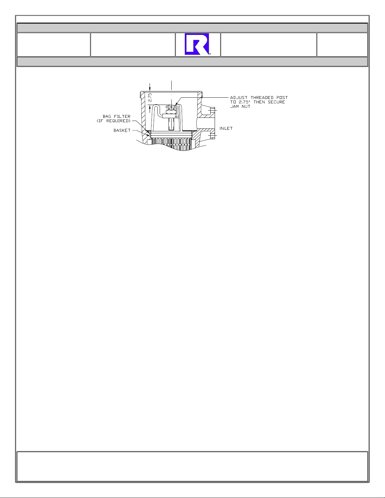
I. Installation of Bag Filter Vessel (Diagram A)
Please remove all shipping and crating materials carefully. Be sure to remove the plugs from the inlet
and outlet openings, gauge ports, etc. Dispose of desiccant package and all shipping materials safely.
The Model CR8 Filter unit is capable of having several different piping variations based upon the outlet
style of your unit. The inlet service line should be connected to the inlet flange located near the top of
the unit (above the basket level).
The outlet service line should be connected to the outlet flange, located near the middle or bottom of the
unit depending upon the piping requirements of your system (below basket level).
Flanged Joints: As with all other thermoplastic piping components, the maximum non-shock operating
pressure is a function of temperature. Please refer to the Pressure-Temperature Rating Chart in this
manual. Remember to consider that when using thermoplastic piping components, the allowable
pressure rating may be significantly less than allowed for the CR8 filter vessel.
When it is necessary to bolt plastic and metal flanges, use flat face metal flanges, not raised face, and
use the recommended bolting torque of 20-30ft-lbs. Flange gaskets should 1/8" thick, elastomeric full flat
faced gasket with a hardness of 50 to 70 durometer.
The faces of thermoplastic flanges are tapered back away from the orifice area at a ½ to 1 degree pitch
so that when the bolts are tightened the faces will be pulled together generating a force in the fluid path
area to improve sealing.