Rosen AV7700 User manual

Rosen Entertainment Systems Copyright 2011 All Rights Reserved
AV7700 System Installation Guide
AV7700 Installation Guide
Lexus RX350/400/400H
NOTICE OF INTENDED INSTALLATION AND USE
ROSEN ENTERTAINMENT SYSTEMS VIDEO PRODUCTS ARE NOT INTENDED FOR VIEWING
BY THE DRIVER, AND ARE TO BE INSTALLED ONLY TO BE VIEWED BY REAR-SEAT
OCCUPANTS.
IMPROPER INSTALLATION COULD DISTRACT THE DRIVER OR INTERFERE WITH SAFE
OPERATION OF THE VEHICLE, WHICH COULD RESULT IN SERIOUS INJURY OR DEATH,
AND COULD ALSO VIOLATE STATE LAW.
ROSEN ENTERTAINMENT SYSTEMS DISCLAIMS ANY LIABILITY FOR ANY BODILY INJURY
OR PROPERTY DAMAGE THAT MAY RESULT FROM ANY IMPROPER OR UNINTENDED
INSTALLATION AND/OR USE.
STOP
Damage to the vehicle may occur
Do not proceed until process has been completed
CAUTION
CAUTION
Process must be carefully observed in order to reduce
the risk of damage to the accessory or vehicle
CRITICAL
Process must be carefully observed in order to ensure a
quality installation
TOOLS and EQUIPMENT
Specific tools and equipment recommended for this
process
SAFETY RISK
Observe safe practices, this process can be dangerous
and there is a risk of personal injury
TESTING and TROUBLESHOOTING
Content specific testing and troubleshooting points
AV7700 Lexus Seat Back Headrest Solution

Installation Guide AV7700
Rosen Entertainment Systems Copyright 2011 All Rights Reserved
AV7700 System Installation Guide AP2004-LX Rev A
Page 2
PREPARING FOR THE INSTALLATION
Before you start, please read these critical steps below
STEP
1
BEFORE YOU START THE
INSTALLATION,
READ THIS GUIDE!
VISIT
Rosen Dealer Central
For the latest Updates, Corrections and
Technical Tips about this product and installation
www.RosenDealerCentral.com
CHECK THE BATTERY
Test the battery voltage to make sure it’s fully
charged to a minimum of 12.8 VDC
This only takes seconds and can save hours of
troubleshooting later.
TURN THE VEHICLE
OFF
Keep the Vehicle Off during the installation to
avoid setting various Vehicle Fault sensors
Keep the Vehicle OFF during the
installation
Failure to follow this may cause the AIRBAG
FAULT SENSOR to become enabled. Dealer
Service Departments charge a significant fee to
reset the Fault Sensor.

Installation Guide AV7700
Rosen Entertainment Systems Copyright 2011 All Rights Reserved
AV7700 System Installation Guide AP2004-LX Rev A
Page 3
Prepare Mounting Bracket
You will need to assemble the vehicle specific mounting brackets.
The following steps will guide you through this process
STEP
2
Locate mounting bracket assembly as well as
hardware mounting kit.
Insert AV7700 mounting bracket into cross-
bar as shown
Use included Phillips screws to secure
mounting bracket to cross-bar

Installation Guide AV7700
Rosen Entertainment Systems Copyright 2011 All Rights Reserved
AV7700 System Installation Guide AP2004-LX Rev A
Page 4
Attaching Mounting Bracket To Electronics
Attach mounting brackets to electronics by using 4 supplied screws
See below for more details
STEP
3
Place the AV7700 electronics system on clean flat
surface.
Attach mounting bracket using supplied screws.
See below for further details
= Screw Location

Installation Guide AV7700
Rosen Entertainment Systems Copyright 2011 All Rights Reserved
AV7700 System Installation Guide AP2004-LX Rev A
Page 5
Attach Color-Matched Material
Attach mounting bracket wrap to AV7700 electronic mounting brackets
STEP
4
Each AV7700 kit is supplied with color-matched
monitor back covers and mounting bracket wrap
based on application ordered.
Route cables underneath wrap material as shown
at right
Align back cover with AV7700 mounting holes
and snap into place as shown at right

Installation Guide AV7700
Rosen Entertainment Systems Copyright 2011 All Rights Reserved
AV7700 System Installation Guide AP2004-LX Rev A
Page 6
CAUTION
CAUTION
Installing AV7700 Electronics
You will need to install the AV7700 electronics and route the cable through the seat backs. The following
steps will guide you through this process.
STEP
5
Detach/release seat access cover at bottom of
seat.
This will expose 2 Phillips screws that need to be
unscrewed to release seatback.
Seatback removed
Remove upper J-Clip to expose mounting hole

Installation Guide AV7700
Rosen Entertainment Systems Copyright 2011 All Rights Reserved
AV7700 System Installation Guide AP2004-LX Rev A
Page 7
CAUTION
CAUTION
CAUTION
Left mounting hole
Remove upper J-Clip on right to expose right
side mounting hole
Unhook J-Clip from crossbar to allow Rosen
mounting bracket to attach.
Insert mounting bracket into seat back and
make sure it does NOT restrict safety cable.
NOTE: Some vehicles are equipped
climate controlled seats which include a
fan inside seatback. Be sure that Rosen
mounting bracket does NOT obstruct fan
functionality
Hook mounting bracket into cross bar

Installation Guide AV7700
Rosen Entertainment Systems Copyright 2011 All Rights Reserved
AV7700 System Installation Guide AP2004-LX Rev A
Page 8
CAUTION
CAUTION
Attach bracket to LEFT mounting hole using
supplied nuts and bolts
Attach bracket to RIGHT mounting hole using
supplied nuts and bolts.
Repeat this process for each seat. Once
complete, route cables to bottom of seat and
route towards area underneath driver’s seat
Locate interface module underneath driver’s
seat.
Locate proper power source at driver’s kick panel
Yellow = 12Volt Accessory
OEM Ground = Ground
Test with digital multimeter before connecting
Install complete

Installation Guide AV7700
Rosen Entertainment Systems Copyright 2011 All Rights Reserved
AV7700 System Installation Guide AP2004-LX Rev A
Page 9
Routing Harnesses and Making Connections
You will need to route the harnesses and make the power connections to the vehicle.
Proper routing of cables is crucial to making sure cables do not get damaged
STEP
6
This system requires a minimum of 12V (+) ACC Switched and Ground (-) to operate. The 12V (+)
ACC Switched source must be capable of supplying a minimum of 7A.
Wiring Diagram STEP
7

Installation Guide AV7700
Rosen Entertainment Systems Copyright 2011 All Rights Reserved
AV7700 System Installation Guide AP2004-LX Rev A
Page 10
Initial Test, Reassembly, and Pre-delivery Re-test
You will need to fully test the system to ensure it is working and connected to the vehicle properly.
The following steps will guide you through this process
STEP
8
Step 1: INITIAL TEST (Do this BEFORE you reassemble any trim panels)
a. Reconnect the vehicle battery if needed
b. Install batteries into the remote control, headphones and game controllers
c. Start the vehicle (ensure that it is safe to do so, there are no tools or people under
the hood)
d. Perform the following steps on each headrest to ensure proper operation:
•Close and re-open the unit several times
•With the display open, insert a DVD (in good condition) and select play
•Check the audio on the IR headphones
•Press the Speaker button and adjust the vehicle radio frequency as needed to
check the audio
•Select and play the internal games
•Eject the disc
•Turn off the vehicle and wait for the unit to turn off
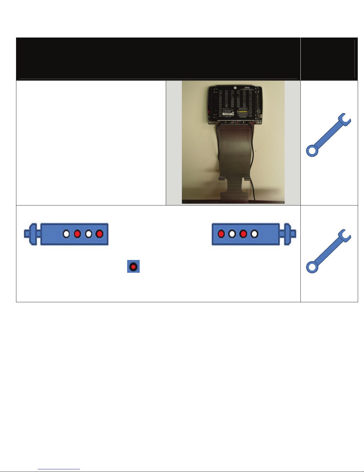
e. If the system does not function properly, reset the system by pressing and holding
the reset
button located near the eject button
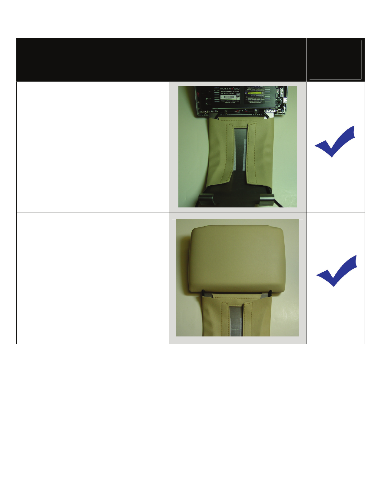
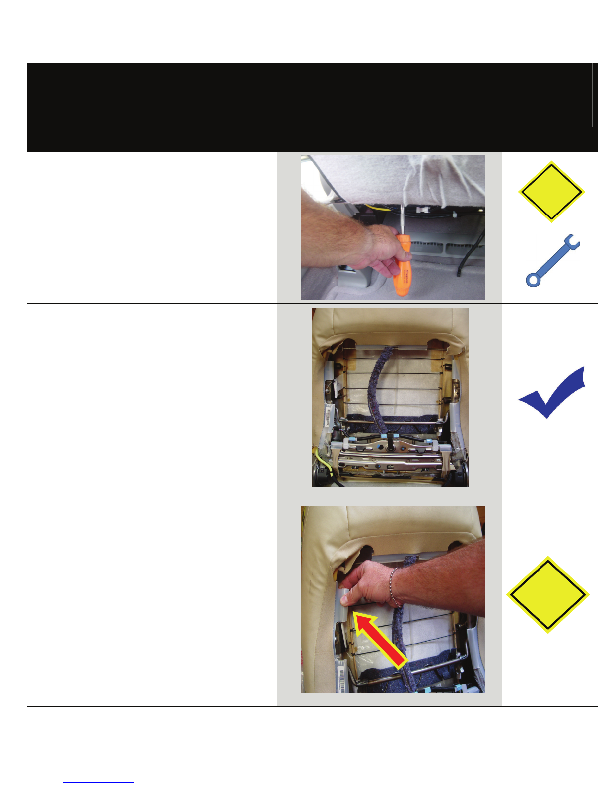
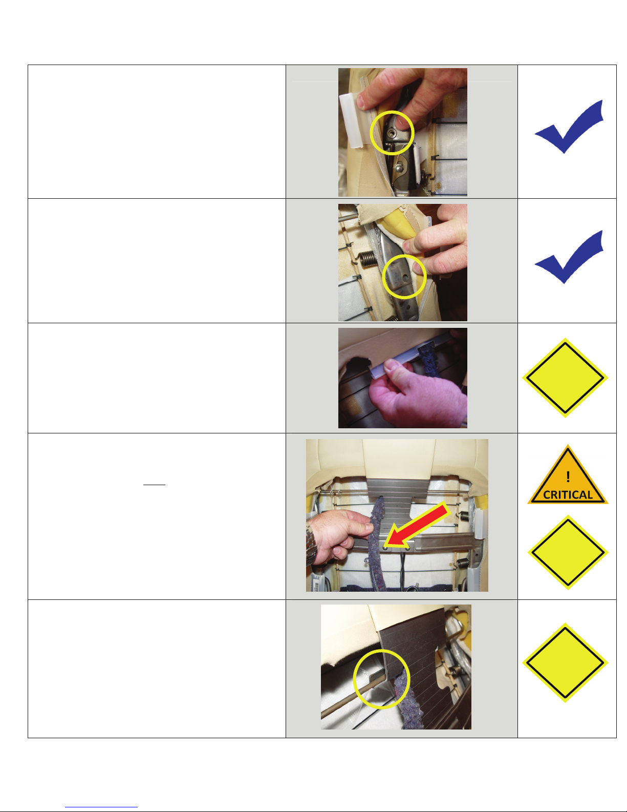
Step 2: REINSTALL all trim panels removed during the installation using care not to damage
any harnesses
Step 3: PRE-DELIVERY AND RE-TEST
a. Start the vehicle (ensure that it is safe to do so, there are no tools or people under
the hood)
b. Perform the following steps
•Insert a DVD (in good condition) and select play
•Re-check IR headphones and FMT audio
•Eject the disc
•Remove the protective films and clean the unit as needed
c. Place the Owners Information package in the glove compartment
d. Place the IR headphones, remote control and game controller in a convenient location

Installation Guide AV7700
Rosen Entertainment Systems Copyright 2011 All Rights Reserved
AV7700 System Installation Guide AP2004-LX Rev A
Page 11
Installer Settings
The steps below will show you how to access the installer settings menu this process
STEP
9
To access install setup menu: use the remote control, press
“EJECT-ENTER-1-1-2-0”
•To change AUX 2 input labeling, highlight AUX 2 label and
scroll left/right using arrows.
•To select EXT FMM, highlight EXT FMM and select on.
•POD ADDR is used to manually set pod address
AutoÆaddress is based on which port the pod is plugged
into.
•Selecting A or B allows you to manually set the pod’s
address
When manually selecting POD ADDR, an OSD will appear
on opposite pod displaying what pod it will be
Specifications
Supply Voltage : 12V (+) ACC negative ground system, 11-16VDC operating range
Current Consumption : 7A max operating
Video Signal : Composite video 1.0Vp-p 75 , NTSC/PAL
Audio Signal : Audio Output : 2Vrms, line output
IR Audio Signal : Channel A= 2.3 MHZ / 2.8 MHZ and Channel B= 3.2 MHZ / 3.8 MHZ
Discs Played : (1) 5” (12cm) DVD-VIDEO Disc
(2) Compact Disc (CD-DA/CD-R/CD-RW/MP3)
Operating Temperature : 0C to +60C
Note: Specifications and designs are subject to modification without notice.
Troubleshooting process
No headphone audio
The Headphone audio should be preset at all times, unless the MUTE is set to on
Solution: Press the MUTE Button to enable the audio and turn the MUTE OFF.
Solution: Confirm the headphones have fresh batteries and are turned on, and the ON LED
Indicator is Illuminated.
Missing Channel B Audio
System includes a monitor A and monitor B. Monitor A is channel “A” on headphones and monitor B
is channel “B” on headphones. If audio is not present, check the following.
Solution: Check A/B switch on headphones.
Solution: Reset the system
Solution: Check all cable connections

Installation Guide AV7700
Rosen Entertainment Systems Copyright 2011 All Rights Reserved
AV7700 System Installation Guide AP2004-LX Rev A
Page 12
Service and Optional Parts List
Part Number Description Part Number Description
AP1003 Interface Module AP1011 Harness, AUX IN
AP1008 Harness, Power AP1043 Remote Control
AP1010 Harness, Interface AP1015 Mounting Bracket
AP1007 Control, Game System AP2001 Monitor/Electronic w/ DVD
AC3640 Headphones, 2 CH. Fold Flat AP2002 Quick Start Guide
AP2003 Owner’s Manual AP2004 Installation Guide
AP1029 Warranty Card AP1017 Cable Routing Tool
AP2020 Harness, Interface (Black w/ Gray) TY100RX Hardware/Mount Kit
AP1021 Harness, Interface (Black w/ Black) AP2060-T38 Bracket Cover, Parchment
AP2010-T38 Monitor Back Cover, Parchment AP2060-B06 Bracket Cover, Black
AP2010-B06 Monitor Back Cover, Black AP2060-G13 Bracket Cover, Lt. Gray
AP2010-G13 Monitor Back Cover, Lt. Gray
www.RosenEntertainment.com
Other manuals for AV7700
4
Table of contents
Other Rosen Car Video System manuals

Rosen
Rosen R6500 User manual

Rosen
Rosen AC3003 User manual

Rosen
Rosen UN7000 Programming manual

Rosen
Rosen T10 User manual

Rosen
Rosen AV7700B User guide

Rosen
Rosen A8 User manual

Rosen
Rosen AV8900H User manual

Rosen
Rosen A9 User manual

Rosen
Rosen DA-7169 Quick start guide

Rosen
Rosen MAZDACX-7 DS-MZ0740 User manual

Rosen
Rosen AV-BW0801-B21 Owner's manual

Rosen
Rosen DS-TY10A0 Toyota 4-Runner User manual

Rosen
Rosen A7 User manual

Rosen
Rosen ClearVue Ultra User manual

Rosen
Rosen ClearVue Overhead Monitor User manual

Rosen
Rosen Rosen inVUE II User manual

Rosen
Rosen AV7500 User manual

Rosen
Rosen AV7950H User manual

Rosen
Rosen DS-UN0810 User manual

Rosen
Rosen T8 Reference guide