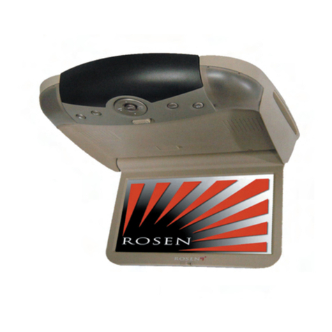
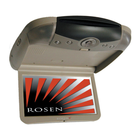
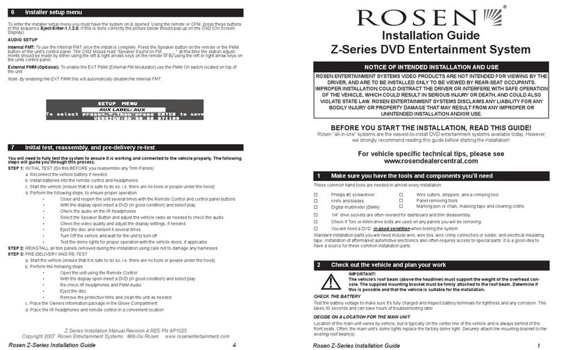
Rosen A8 User manual

Rosen A8Installation Guide 1
A8DVD Entertainment System
Installation Guide
BEFORE YOU START THE INSTALLATION, READ THIS GUIDE!
Rosen “all-in-one” systems are the easiest-to-install DVD entertainment systems available
today. Even though the A8is very easy to install, we still strongly recommend reading this
guide before starting the installation! Below is an outline of the installation process, showing
the installation sequence we recommend, and the pages that describe each step.
Contents - Steps to a successful installation:
Step One: Make sure you have all the components and tools you’ll need 2
Step Two: Check out the vehicle and plan your work -
console location, harness routing, etc. 3
Step Three: Cut the headliner and mount the Bracket 4-8
Step Four: Route the harnesses and make all wiring connections 9
Connecting the Domelight Harness 10
Step Five: Install the A8and the FM Modulator 11
Step Six: Test the system, reassemble the vehicle trim panels,
quickly test one more time, and you’re finished! 12
Frequently Asked Questions 13
A8System Diagram 14
A8Installation Manual Revision A RES PN 9100389
Copyright 2003 Rosen Entertainment Systems
866-Go Rosen www.rosenentertainment.com
NOTICE OF INTENDED INSTALLATION AND USE
ROSEN ENTERTAINMENT SYSTEMS OVERHEAD VIDEO PRODUCTS ARE NOT INTENDED FOR
VIEWING BY THE DRIVER, AND ARE TO BE INSTALLED ONLY TO BE VIEWED BY REAR-SEAT
OCCUPANTS. IMPROPER INSTALLATION COULD DISTRACT THE DRIVER OR INTERFERE WITH
SAFE OPERATION OF THE VEHICLE, WHICH COULD RESULT IN SERIOUS INJURY OR DEATH,
AND COULD ALSO VIOLATE STATE LAW. ROSEN ENTERTAINMENT SYSTEMS DISCLAIMS ANY
LIABILITY FOR ANY BODILY INJURY OR PROPERTY DAMAGE THAT MAY RESULT FROM ANY
IMPROPER OR UNINTENDED INSTALLATION AND/OR USE.

2Rosen A8Installation Guide
1 Make sure you have the components and tools you’ll need
MAKE SURE YOU HAVE ALL THE NEEDED COMPONENTS
Before you begin to disassemble the vehicle, make sure you have all the appropriate kit
contents. Determine which optional components are to be installed, if any.
Standard Components: Model # RES Part #
!A8overhead console in Neutral or Gray AC3400 Neutral 9100351
AC3401 Gray 9100352
!20mm Short Trim Ring in Neutral or Gray CV2029N Neutral 9100180-2
CV2029G Gray 9100181-2
!Mounting bracket AC3206 9100270
!Hardware pack AC3104 9100240
!FM Modulator AC3195 9100244
!Harnesses and cables: *(if used in the installation)
Black power harness AC3197 9100242
Blue FM Modulator harness AC3191 9100265
Yellow Audio/Video Out cable * AC3192 9100261
Four-wire Domelight Harness AC3063 9100282
!Remote Control AC3205 9100269
!Two (2) Infrared Wireless Headphones AC3003 4007-0158-000
!Owner’sManual AC3203 9100236
Optional Components:
!CV4000 TV Tuner kit ( AC3105 TV Tuner, AC3024 harness, AC3061 TV antenna)
!R5000-series VCP and optional harness AC3024 (not included with VCR)
!AC3002 TV Antenna (if installing an R5000-series VCR with TV tuner).
!CV9200 Second Screen Kit (M9 9” monitor, AC3193 cable)
!AC3194 Universal Aux Input cable. Converts a TVT/VCP input to an AUX input.
MAKE SURE YOU HAVE THE TOOLS AND PARTS YOU’LL NEED
These common hand tools are needed in almost every installation:
!Phillips #2 screwdriver
!Knife and blades
!Digital multimeter (DMM)
•1/4” drive sockets are often needed for dashboard and trim disassembly.
•3/8” drive sockets are often needed for seat removal and reinstallation.
•Check if Torx or Allen-drive bolts are used on any panels you will be removing ,or if
special tools are needed to remove the radio.
•You will need a DVD and a CD in good condition when testing the system.
Standard installation parts you will need include wire, wire ties, wire crimp connectors or
solder, and electrical insulating tape. Installation of aftermarket automotive electronics
also often requires access to special parts such as antenna adapters. It is a good idea to
have a source for these common installation parts.
!Wire cutters, strippers,and a crimping tool
!Panel-removing tools
!Marking pen or chalk, and cleaning cloths

Rosen A8Installation Guide 3
!
2 Check out the vehicle and plan your work
IMPORTANT!
The vehicle’s roof beam (above the headliner) must support the
weight of the overhead console. The supplied mounting bracket must
be firmly attached to the roof beam. Determine if this is possible to
ensure that the vehicle is suitable for an A8installation.
CHECK THE BATTERY
Test the battery voltage and inspect battery terminals for tightness and any corrosion. This
takes 30 seconds and can save hours of troubleshooting later.
DECIDE ON ALOCATION FOR THE A8
Location of the A8varies by vehicle, but is typically on the center line of the vehicle and is
always aft of the front seats. Often, the A8’s domelights replace the factory dome light.
Always attach the mounting bracket to the existing roof cross beams.
NOTICE OF INTENDED INSTALLATION AND USE
ROSEN ENTERTAINMENT SYSTEMS OVERHEAD VIDEO PRODUCTS ARE NOT INTENDED
FOR VIEWING BY THE DRIVER, AND ARE TO BE INSTALLED ONLY TO BE VIEWED BY REAR-SEAT
OCCUPANTS. IMPROPER INSTALLATION COULD DISTRACT THE DRIVER OR INTERFERE WITH
SAFE OPERATION OF THE VEHICLE, WHICH COULD RESULT IN SERIOUS INJURY OR DEATH,
AND COULD ALSO VIOLATE STATE LAW. ROSEN ENTERTAINMENT SYSTEMS DISCLAIMS
ANY LIABILITY FOR ANY BODILY INJURY OR PROPERTY DAMAGE THAT MAY RESULT
FROM ANY IMPROPER OR UNINTENDED INSTALLATION AND/OR USE.
The A8requires adequate roof support and a relatively flat headliner. Before you begin
installation, drop the dome light and partially drop the headliner, and verify that you have
sufficient clearance and sufficient support from a roof beam. Inspect the vehicle roof and
headliner area and consider the following questions.
!Does the vehicle have overhead climate controls? Does their location interfere with
installation of the A8?
!Is the dome light located where it would interfere with your installation of the A8?
The A8has built-in dome lights which connect to the existing vehicle domelight
wiring, so the A8can replace the factory dome light.
!Does the vehicle headliner contour require using the optional AC3062 Universal
Tall Trim Ring and modifying it? (Make sure you have the tools needed).
CHECK OUT THE VEHICLE RADIO
The FM modulator usually must be located behind the vehicle radio, since it connects to
the radio antenna cable. Remove the radio first to determine the type of antenna connector
it uses. Some antennas require optional adapters - make sure you have them, if needed!
IMPORTANT!
Before you disconnect the vehicle radio, make sure that you have the
security code, if the radio uses a code! Check the vehicle owner's
manual for details.
!

4Rosen A8Installation Guide
3 Cut the headliner and mount the bracket
IMPORTANT!
DO NOT BEGIN THIS STEP UNTIL YOU HAVE INSPECTED THE HEAD-
LINER, THE ROOF BEAM, AND ALL OTHER ESSENTIAL AREAS, AND
VERIFIED THAT THE INSTALLATION CAN BE SUCCESSFULLY COM-
PLETED! IT IS YOUR RESPONSIBILITY TO MAKE SURE THE INSTAL-
LATION IS SAFE, SECURE, AND APPROPRIATE TO THE VEHICLE.
STEP 1: SELECT A MOUNTING METHOD
!!
!!
!Standard mounting. You will need to cut the headliner in order to create a path for the
cables and to mount the bracket. Sometimes slight modifications to the included trim
ring are needed. The bracket will mount laterally and the A8mounting screws must be
able to line up with the threaded standoffs on the bracket as shown.
Headliner
Trim
Ring
Cables
Bracket Cable Exit
Bracket oriented laterally
Vehicle Roof
Roof Beam
Front ofVehicle
!
(Continued)
Connectors
Threaded standoffs
for Mounting Screws
Threaded standoffs
for Mounting Screws
ENTER
OPEN
SOURCE
Driver’s side
mounting holes
Passenger
side
mounting
holes

Rosen A8Installation Guide 5
!!
!!
!Standard mounting with a spacer. This is the same as Standard mounting except that
optional spacers are inserted between the Bracket and the beam to allow extra room.
Headliner
Trim
Ring
Cables
Bracket
Cable Exit
Bracket oriented laterally
Vehicle Roof
Roof Beam
Front ofVehicle
Optional Spacers
(included in
hardware kit)
Optional Spacer(s)
(not included)
!!
!!
!Custom mounting. This involves modifying the bracket or using appropriate
brackets, and can also involve using an AC3062 Universal Tall Trim Ring,
and modifying it to fit the vehicle. As with every installation, it is your responsibility to
make the installation safe, secure, and appropriate to the vehicle. RES does not
recommend recessed mounting (without a trim ring) due to possible high-temperature
operation issues.
Headliner
Trim Ring
Cables
Bracket (Bent)
Cable Exit
Bracket oriented lengthways
Vehicle Roof
Roof Beam
Front of Vehicle
Roof Beam

6Rosen A8Installation Guide
FRONT ofVehicle
Cable Exit
Mounting screw/
standoff holes
Cardboard template
(Trim Ring Footprint)
IMPORTANT! If you cut away too much of the headliner, you will create
a direct path for heat to radiate from the roof of the vehicle into the DVD
drive. On very hot days, this type of installation could trigger the A8
temperature protection (the DVD drive shuts down above 140OF). To
minimize heat exposure, only cut the headliner as shown.
!
Headliner
Trim
Ring
Cables
Bracket Cable Exit
Vehicle Roof
Roof Beam
Front ofVehicle
Optional Spacer(s)
Threaded
standoffs
Headliner between
DVD drive and roof cavity
STEP 2: CUT THE HEADLINER
1 Remove the cardboard template (it
is perforated into the inner box). Do not
cut along the outside of the template!
Center the template on the center line of
the vehicle by measuring the width of
theheadliner, dividing by two, and mak-
ing a chalk mark on the center line.
Always double-check that the
template is correctly oriented
front-to-rear.
2Double-check the template’s front/rear orientation and position.
3 Mark the template cut locations onto the headliner with a pencil, marker, or chalk. Trace
the cable exit rectangle, and mark the center of each of the mouting screw holes.
Note: If you plan on removing unused standoffs from the bracket, you can reduce the
number of holes to cut - see page 7.
4 Using a sharp blade, carefully cut the headliner. Cut on the inside of your lines. Cut
a rectangle for the cable exit, and small squares in each of the screw locations. (Cutting
squares makes the alignment process much easier than drilling precise holes). If the
beam is not directly above the cable exit rectangle, cut a small access hole to allow you
to screw the bracket to the beam. Do not cut near the edge of the template outline!
5 Test-fit the mounting bracket into the headliner opening from above.

Rosen A8Installation Guide 7
CAUTION!
Make sure that the screws you use to mount the bracket and the A8
are not too long! If the screws you select are too long, you will dam-
age the roof of the vehicle. Take great care when planning this part of
your installation.
Optional spacers may be needed
With some vehicle roof beams, you may need to use optional spacers to mount the bracket
to the beam. Some thick headliners require spacers between
the bracket standoffs and the A8.
If test-fitting indicates that you need to use the
included spacers between the A8and the bracket standoffs,
pre-insert each mounting screw into the A8from below as
shown. Then press the spacer over the tip of the screw.
The spacers should hold the screws in place.
After you have pre-inserted all four screws, go to the next step - do not mount the A8yet!
Headliner
Trim
Ring
Cables
Bracket Cable Exit
Bracket oriented laterally
Vehicle Roof
Roof Beam
Front ofVehicle
Optional Spacers
(included in
hardware kit)
Optional Spacer(s)
(not included)
Bending or modifying the bracket
The bracket is designed to be able to be bent or shortened as needed. You may also
want to remove the four unused threaded standoffs with a hammer as shown, but
only when you are certain they will not be needed.
STEP 3: MOUNT THE BRACKET
Stand
!
Insert
mounting
screw
Sturdy workbench
Strike firmly with ball-peen hammer
Bend/
break
lines
Bend/break lines

8Rosen A8Installation Guide
Bend or break Bracket at this point
to create a cable exit! (See Pages 5, 7)
Threaded
standoffs
for
Mounting
Screws
Connectors
Threaded
standoffs
for
Mounting
Screws
Threaded
standoffs
Bend/break lines
Slots for screws or
optional AC3024
stabilizing
mounting feet
Front ofVehicle
Threaded
standoffs
Threaded
standoffs
Long-axis Bracket Positioning
MOUNT THE BRACKET (continued)
Remove the headliner trim and any grab handles
over the rear door frame. Slide the bracket in
between the headliner and the roof. Mount the
bracket to the roof beam through the opening you
made in the headliner. A minimum of four short
screws must be used to mount the bracket.
CAUTION!
Front ofVehicle
Threaded
standoffs
Threaded
standoffs
Lateral Bracket Positioning
Connectors
Threaded standoffs
for Mounting Screws
Threaded standoffs
for Mounting Screws

Rosen A8Installation Guide 9
4 Route the harnesses and make all wiring connections
Basic connections are described in this section. For more information on wiring, see the
system wiring diagram on page 14.
INSTALLATION PRECAUTIONS
• Use caution to assure that harnesses and cables are protected from sharp
edges. Where necessary, add tape to cover sharp surfaces.
• Avoid sharp bends (always less than 90O, but lessthan 45O is preferred).
• The locking connectors in this system require that even force be applied to the
release latch when harnesses are disconnected. Failure to use reasonable care
will damage the connector and cause system failure.
CABLE AND HARNESS ROUTING
1 Starting at the headliner cutout, route the black power harness and the blue FMM cable
to the underdash area. Leave about six inches of cable hanging through the cutout.
Allow enough slack in the harnesses above the headliner to allow working room. You
may want to leave a short loop hanging out the side of the headliner until final re-
assembly (this makes stuffing cables into the headliner easier when you mount the A8).
2 You may want to secure the cables with tape so they lie flat. This makes it easier to
reassemble the vehicle trim correctly, especially with sunroof vehicles.
3 If the Auxiliary Input harness or any other optional harnesses are being used, route
them from the headliner cutout to their destination. Remember to leave working slack.
When using optional harnesses, you may need to split the harness paths, routing
some harnesses down one side of the vehicle and the rest down the other.
CONNECTING THE POWER HARNESS
The A8requires both constant 12V (+) and switched 12V (+) energized when the key is in
the Accessory position. These can be found at the ignition switch harness. The A8ground
wire should mount to bare metal, using a factory ground bolt whenever possible.
Power Harness Connections:
Yellow 12V (+) Constant Power (Fused 7.5 A)
Red 12V(+) Switched Accessory (Fused 1 A)
Black Chassis (-) Ground
Blue 12V(+) output when FM Modulator is on (not used in most installations)
IMPORTANT:
- Grounding the Blue power harness wire will cause system failure.
- Connecting the Red wire to constant 12V(+) causes battery drain
and premature battery failure.
CONNECTING THE FM MODULATOR HARNESS
FM Modulator Connections:
Gray 12V(+) FMM Control On/Off Connect to Red of FM Modulator
Black/White FMM Ground Connect to Black of FM Modulator
Blue/White, Brown Not used - cap off to avoid shorting to ground
Red, White RCAs Red and White input RCAs on FM Modulator
!
10Rosen A8Installation Guide
Connecting the Domelight Harness
The A8 has a domelight harness which connects to the vehicle domelight wiring. Remove
the vehicle domelight, find the vehicle domelight harness connector, and unplug it. Use a
digital multimeter to test all the wires in the vehicle domelight connector, to determine which
of the following domelight wiring systems is being used.
Notes:
Many vehicles have domelight delay timers which keep the lights on for a few sec-
onds after the doors are closed, or which shut off the domelight after it has been on
for too long. Make sure these timers don’t defeat your testing - occasionally turn the
ignition key on and off, and open and close all the doors.
The wire color and operation at the domelight is not always the same as the wiring in
the kick panel - alarm wiring information is often not accurate for these connections.
Always determine how the wires work at the domelight, not at the kick panel !

Negative door trigger systems have the following wires:
Constant 12V(+).
Negative door trigger. This will test as switched (-) ground when the doors are open,
and either 12V(+) or an open circuit when the doors are closed.
Constant ground.
Note: This wire may not be present if the dome light grounds through its mounting
screws, or if it does not have an on/off switch built in.
Positive door trigger systems (many Ford and GM) have the following wires:
Constant Ground.
Note: This wire may not be present if the domelight grounds through its mounting
screws.
Positive door trigger. This will test as switched 12V(+) when the doors are open,
and either (-) ground or an open circuit when the doors are closed.
Constant 12V(+). Note: This wire may not be present if the dome light does not have
an on/off switch built in. (In new GM cars, Rosen recommends not
using this orange wire - connect to another source of 12V constant).
Domelight Harness Connections:
Yellow wire to 12V(+) constant voltage (Note: in newer positive- trigger GM cars, do not
use the GM 12V constant orange wire - connect to another source of 12V constant).
Black wire to vehicle chassis (-) ground.
Green wire to the vehicle (-) door trigger wire, or Purple wire to the (+) door trigger wire.
Note: If the Green wire is unused, you must cap it off to prevent it shorting to ground!
Note: The A8Domelight has a built-in timer that limits the domelight to around five min-
utes of illumination. This is to prevent accidental battery drain. To turn the domelight
back on after the timer has turned it off, just press the domelight button again.

Rosen A8 Installation Guide 11
!
!
5 Install the A8 and the FM Modulator
1 Test-fit the A8 and the trim ring to determine if the trim ring or headliner should be
trimmed. Optimally, the top of the trim ring will be in complete contact with the roof
beam, without any gaps – achieving this may require trimming the edges of the trim ring
(if there are gaps, the domelights may backlight them and make them more noticeable).
You can also insert foam above the headliner to help seal gaps from above. Some
thicker headliners may require the use of the included spacers - see Page 7 for details.
2 Plug in all the harnesses and cables that you are using, following the color-coded label
on the top (remember the domelight harness). The video output and auxiliary harnesses
aren’t used in all installations.
3 Mount the A8 to the bracket with four machine screws of a safe length. Four 45mm-long
machine screws are included - use only if they are appropriate for your installation.
Some thicker headliners may require the use of the included spacers - see Page 7 for
details and more information.
CAUTION!
Make sure that the screws you use to mount the A8 are not too long!
If the screws you select are too long, you will damage the vehicle roof.
IMPORTANT!
Do NOT overtighten! Check for proper deployment of the screen and
proper ejection of discs – if there is any binding, check for uneven
screw torquing. Difficulty in ejecting discs means that the front
screws are too tight. Binding indicates that the side edges of the trim
ring need to be trimmed to relieve pressure on the sides of the A8.
4 Note the FM Modulator frequency switch setting - either 87.9FM or 88.3 FM. Unplug the
radio’s antenna cable - connect it to the FM Modulator. Connect the FM Modulator to
the radio antenna port. Mount the FM Modulator, using wire ties as needed.
Note: Do not re-assemble the vehicle yet!
A9 DVD Entertainment System
FMM TV TunerPower VCP Screen 2
CLASS 1 LASER PROD CT Apparatus Claims of
u.S. Patent Nos. 4,631,603,4,577,216,4,819,098, and
4,907,093 Licensed for Limited Viewing ses Only.
All Rights Reserved. Covered under one or more of the following S Patents:
5,946,055 6,124,902 6,157,418 6,115,086 6,246,449 6,181-387 6,292,236
6,059,255 6,529,123 6,412,848 6,364,390 Design 456,789 and others pending
For limits of liability please consult owner’s Manual.
A8

12Rosen A8Installation Guide
6 Test, reassemble, and basic re-test
Remember - until you test your installation, you’re not finished! Testing the system before
you reassemble the vehicle can save you time troubleshooting any problems. Quick, basic
testing after reassembling the vehicle assures that everything is ready to go for your cus-
tomer.
INITIAL SYSTEM AND INSTALLATION TEST
1 Reconnect the battery (if disconnected).
2 Make sure the vehicle can be started safely (for example, there are no tools or workers
under the hood and you have appropriate exhaust ventilation).
3 Start the vehicle.
4 Tune radio to the FM Modulator frequency (either 87.9 FM or 88.3 FM).
5Open the A8monitor to power up system.
6 Insert the battery into the remote control, and a DVD into the slot.
7 Test “TV Tuner” or “VCP” sources if installed, and the “Auxiliary Input” source if in use.
8 Check both headphones for proper operation (after properly inserting the batteries).
9 Listen to both DVD and CD audio with the FM Modulator on (use the Speaker On/Off
button on the remote or on the front of unit). If the DVD Audio level is too low or the CD
Audio level is too high, adjust the FM Modulator until both are appropriate.
10 Test for Audio and Video noise with the engine running and the alternator loaded (head-
lights on high, rear defroster on). If noise is heard or seen:
!Check your ground connection on the Power Harness Black wire and the
FMM Black/White wire.
!Check the battery voltage and the connection quality of the (+) and (-)
terminals (these should already have been checked).
!Separate the FM Modulator and Power harnesses as far as possible and
retest.
REASSEMBLE THE TRIM PANELS
Carefully reassemble the vehicle. Make sure not to pinch, pierce, or damage any of the
cables or harnesses.
QUICKLY RETEST THE SYSTEM BASICS
After you reassemble the vehicle, quickly retest the system for power-up, audio and
video, and noise to verify that no cables or harnesses were disconnected or damaged
during reassembly.
DELIVER THE VEHICLE
Congratulations! The vehicle is now ready for delivery.

Rosen A8Installation Guide 13
Frequently Asked Questions
Why does the audio seem quiet or distorted?
If this is happening with a DVD, retest with the RES Sound Processing feature turned on.
This feature helps optimize DVD audio for car stereo systems.
Check the disc for damage. With CD-Rs, check the recording level.
Check the FMM level setting. Quiet audio can mean the setting is too low, and distorted
audio can mean the setting is too high. When testing, use both CDs and DVDs - they often
have different audio levels, and adjusting for only one can cause problems with the other.
Why is there no audio coming from the DVD player?
Make sure that the DVD’s Setup Menu Digital Audio output setting is “Off”.
Why are the domelights working backwards?
The green or purple door-trigger input wire is connected to the wrong polarity trigger wire in
the car. See the main wiring diagram on page 14.
Can I use both a Rosen TV Tuner and a Rosen VCP in the same system?
Yes - you’ll use two optional AC3024 harnesses. Make sure not to reverse the connections!
Why doesn’t the optional VCP or TV Tuner work?
Are you pressing the Power button on the A8remote after selecting the TVTuner or VCP
as a source? (The A8Power button only controls them when they are the selected source).
Is the IR mini-jack plugged from the Magenta harness plugged in to the unit?
Is the Blue wire of the VCP connected to the Blue wire of the Magenta VCP harness?
Connect both the Red and Blue of the VCP to the Red of the harness.
Can I use the TV Tuner or VCP inputs for other source units?
Yes, although the user won’t be able to control them with the A8remote. Use the optional
AC3194 Universal Aux Input Cable (PN 9100263) - using the AC3024 TV Tuner/VCR
cable will cause the wrong on-screen display to appear when that source unit is selected.
How can I add an additional screen?
The CV9200 kit has a matching 9” widescreen display with a special cable included
(AC3193) that makes installation and operation with an A8simple and straightforward. The
included video output cable can be used to add any monitors with a composite RCA video
input. RES recommends grounding any added monitors to the same point as the A8.
The system keeps shutting off while I try to test it. Why?
This could be a low-voltage problem - check the battery.
Check power and ground connections. This is a symptom of poor electrical connections.
Make sure you are not using a damaged DVD disc.
Call Rosen Technical Support to determine if any of the internal protection modes are being
triggered - (888) 883-2790.

14Rosen A8Installation Guide
Blue FMM
Cable (AC3191)
AC 3195
FMM
To Radio and
Antenna
RCA
connections
Yellow
12V(+)
Constant
Red 12V(+)
Switched
Accessory
Black
(-) Chassis
Ground
Blue
12V(+)
Controlled
Output
Domelight
Harness (AC 3063)
Yellow: 12V(+) Constant
Black: (-) Ground
Gray: (-) Negative door input
Purple: (+) Positive door input
Note:
Black cables are required,
Gray cables are optional.
(The Green andYellow cables
are included, but not required)
*Wiring Connections,
Optional Magenta
TVTuner/VCP Harness AC3024:
Red 12V(+) Output -
Connect to Red ofTV Tuner, or
Connect to Red and Blue of VCP
Blue Cap off - do not use
Black (-) Ground Lead of Source
Note:When using theTVTuner or VCP
Inputs for other sources, use the Optional
AC3194 Universal Aux Input Cable
(Rosen PN 9100263).
Black Power Cable/ Harness (AC 3197)
Red of FMM to Gray of A8
Black of FMM to Black/White of A8
Blue/White, FMM Harness - Do not use
Brown, FMM Harness - Do not use
A8 connector map
This color-coded label is on the top of the A8.
Plug in cables and harnesses as shown.
Important:
Do not allow
the Blue wire to
short to ground -
system damage
will result.
*Optional
Magenta
Cable,TVTuner
(AC 3024)
*Optional
Magenta
Cable,VCP
(AC3024)
YellowVideo Output Cable (AC 3192)
(Note: When using a second screen, this is replaced by
the AC3193 cable, included with the CV92 second-screen kit)
Rosen A8 SystemWiring Diagram
Front of Unit
(Disc Slot)
FM frequencies:
87.9 or 88.3
Note: Level
adjustment
screw is on
the bottom
of unit
A8 DVD Entertainment System
FMM TV Tuner
Power VCP Screen 2
CLASS 1 LASER PR DUCT Apparatus Claims of
u.S. Patent Nos. 4,631,603,4,577,216,4,819,098, and
4,907,093 Licensed for Limited Viewing Uses nly.
All Rights Reserved. Covered under one or more of the following US Patents:
5,946,055 6,124,902 6,157,418 6,115,086 6,246,449 6,181-387 6,292,236
6,059,255 6,529,123 6,412,848 6,364,390 Design 456,789 and others pending
For limits of liability please consult owner’s Manual.
Table of contents
Other Rosen Car Video System manuals

Rosen
Rosen AV-CY0801-G42 Owner's manual

Rosen
Rosen Z8 User manual

Rosen
Rosen AV7700 DVD ENTERTAINMENT SYSTEM User manual

Rosen
Rosen ClearVue CV6825 User manual

Rosen
Rosen HE0780D User manual

Rosen
Rosen MAZDACX-7 DS-MZ0740 User manual

Rosen
Rosen ClearVue Ultra User manual

Rosen
Rosen DS-TY0820-H11 User manual

Rosen
Rosen CV1005 User manual

Rosen
Rosen R6500 User manual