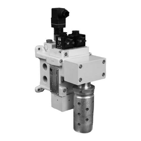
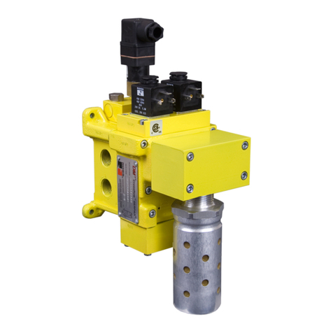
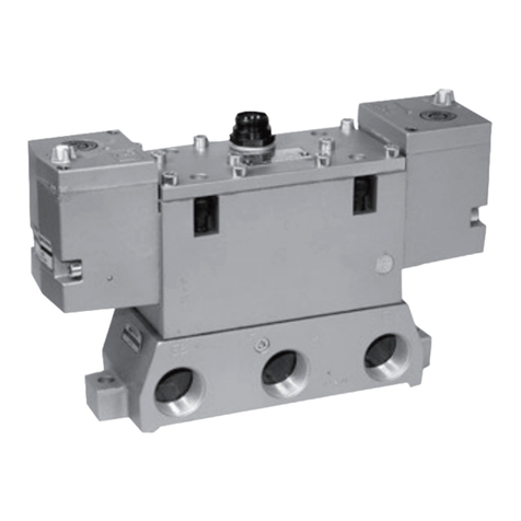
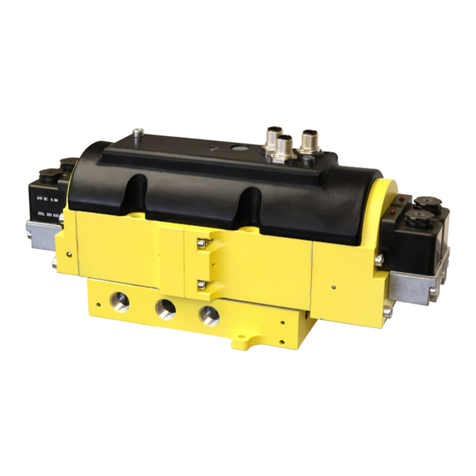
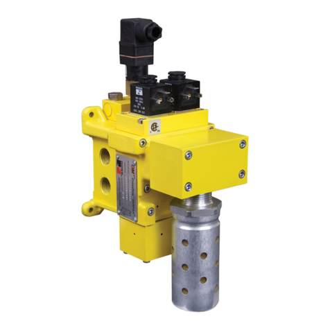
Ross Controls Automatic Valve A04 Series Operating instructions

AUTOMATIC VALVE INDUSTRIAL www.automaticvalve.com
SERVICE INFORMATION
Pneumatic equipment should be serviced only by persons trained and experienced in pneumatic products.
Turn off the electrical supply to the valve. Shut off and exhaust the air supply.
1. Follow appropriate lock-out/tag-out procedures. Do not attempt to service a valve, if you are not familiar with lock-out/tag-out procedures.
2. Turn off electrical power to the valve.
3. Remove valve from all electrical and air power sources.
4. Ensure all stored air power is exhausted.
5. Remove coil by first removing coil pretention nut.
6. Remove operator cap by first removing 4 socket head cap screws.
7. Remove existing serviceable components by “pushing” internal components gently out of the valve body.
8. Clean the spool with a clean cloth.
9. Discard the spring (Single Spring Return models only).
10. Lubricate the designated “+”items in above assembly drawing with a thin film of lubricant - the item should look “WET” with no excess
lubricant visible.
11. Replace components as shown above.
11.1 Replace spring pad (where required) & spring (Single Spring Return Models Only).
11.2 Alternate Tee-seals and spacers.
11.3 Once all 6 Tee-seals are installed, replace the retainer, bushing & piston, and spool.
12. Orientate the operator cap by aligning the open end of the gasket with the pilot hole in the valve body. (For external pilot, this hole is
covered; see Field Conversion on page 3.)
13. Torque cap screws into body to 1,02 N-m (9 in-lbs) ±10%. Alternate tightening of the screws, so cap “squeezes” evenly onto body.
Please read and make sure you understand all instructions before proceeding with the service.
If you have any questions about installation or servicing your product, please contact AUTOMATIC VALVE or your authorized AV
distributor, see contact information listed at the back of this document, or visit www.automaticvalve.com.
SAE 125 Spool Valves – A04 Series
Operating/Service Instructions
Series Valve Type
Kit Model Number Contents
Buna-N Fluoroelastomer Tee -Seals Gasket Piston Seal Spring
A04 Single K-A04-SGL K-A04-SGL-A 6111
Double K-A04-DBL K-A04-DBL-A 612–
Air Line Lubrication of AUTOMATIC VALVE products is not required, but is recommended to maximize service life. Oils should be
compatible with seal material, have an ISO 32 or lighter viscosity, and have an aniline point between 82oC (180oF) and 99oC (210oF).
+= Items that Must Be Lubricated
You have purchased a premium-quality AV pneumatic valve. It is a high quality SAE spool valve,
designed for ease of installation and maintenance.
With care in its installation and maintenance you can expect it to have a long and economical
service life. Before you service your valve, please read the information in this document completely, and save it for future reference.
A general user manual with more detailed information is available online, visit AV's website at www.automaticvalve.com.
Thank You!
Service Kit Installation Instructions
+ TEE-SEALS (6)
+ PISTON SEAL
SPRING
GASKET
CAP RETAINED WITH
M3 SCREWS
TORQUE 1,2 N-M (9 IN-LBS) ±10%
COIL RETENTION NUT
COIL
SPRING PAD
+ SPOOL
+ TEE-SEALS (6)
+ PISTON SEAL + SPOOL
HOUSING GASKET
BODY TO BASE GASKET
CAP SCREW 1/4-20
TORQUE TO 6,7 N-M (59 IN-LBS) ±10% BODY TO BASE SCREWS 5/16-18
TORQUE TO 13,7 N-M (121 IN-LBS) ±10%
HOUSING SCREWS #10-24
TORQUE TO 42 IN LBS ±10%
SPRING

2 AUTOMATIC VALVE INDUSTRIAL. All Rights Reserved.
Valve Operating/Service Instructions
Wiring
Options Pin Number
4 pin
Micro
5 Pin
Micro
5 Pin
Mini Cst.
Schematic
[For SGLSolenoid use Sol B pin out]
(See next Page for
Wiring & Service Diagram)
12345
Lead Connects
To Lead Connects
To Lead Connects
To Lead Connects
To Lead Connects
To
-0-GM
BLK
BRN
RED/YELLOW
SOL
B
GREEN
RED/WHITE
SOL
A
RED/BLACKRED
BLK
1
2
3
4
5
BRN
Red/
White
Sol A
Brown Red Sol B
Black Green Ground Red/
Yellow
Sol B
Brown
Red/
Black
Sol A
Black
-1-Ford
GREEN
2
4
1
5
3
RED/YELLOW
BLK
RED/BLACK
BLK
SOL
B
BRN
RED/WHITE
SOL
A
RED
BRN
Red/
White
Sol B
Brown Red Sol A
Black Green Ground Red/
Yellow
Sol A
Brown
Red/
Black
Sol B
Black
-2
AC -Chrysler
2
4
1
5
3
GREEN RED
BRN
BLK
RED/YELLOW
RED/WHITE
SOL
A
BLK
SOL
B
RED/BLACK
BR
N
Red/
White
Sol A
Brown Red Sol A
Black Green Ground Red/
Yellow
Sol B
Brown
Red/
Black
Sol B
Black
-2
DC -Chrysler
1
5
GREEN
2
4
3
RED/YELLOW
BLK
BRN
RED
RED/WHITE
SOL
A
BLK
SOL
B
RED/BLACK
BR
N
Red/
White
Sol A
Black Red Sol B
Black Green Ground Red/
Yellow
Sol A
Brown
Red/
Black
Sol B
Brown
- - 3GM
BRN
BRN
BLK
SOL
A
SOL
B
GREEN
1
234
5
RED/WHITERED
RED/YELLOW
RED/BLACK
BLK
Red/
White
Sol A
Brown Red Sol B
Black Green Ground Red/
Yellow
Sol B
Brown
Red/
Black
Sol A
Black
- - 4 Ford
BLK
BLK
BRN
BRN
SOL
A
SOL
B
GREEN
1
234
5
RED/WHITERED
RED/YELLOW
RED/BLACK
Red/
White
Sol B
Brown Red Sol A
Brown Green Ground Red/
Yellow
Sol A
Black
Red/
Black
Sol B
Black
- - 5 Chrysler
BLK
BLKBRN
BRN
SOL
A
SOL
B
GREEN
1
2
3
4
5
RED/WHITE
REDRED/YELLOW
RED/BLACK
Red/
White
Sol A
Brown Red Sol A
Black Green Ground Red/
Yellow
Sol B
Brown
Red/
Black
Sol B
Black
6- - GM
BLK
BRN
BR
N
BLK
BROWN
BLACK
BLUE
1
4
3
2
SOL
B
SOL
A Brown Sol A
Brown White -Blue
Sol A
Sol B
(Black)
Black Sol B
Brown None
7- - Ford
BRN
BLK
BLK
BRN
WHITE
BLACK
BLUE
1
43
2
SOL
B
SOL
A Brown -White Sol A
Brown Blue
Sol A
Sol B
(Black)
Black Sol B
Brown None

www.automaticvalve.com 3
Valve Operating/Service Instructions
Assembly: Valve to Manifold Base
Model 413 Assembly Model 416 Assembly
Instructions:
1. STEP 1: Place O-Rings in counterbores in base.
2. STEP 2: Assemble base to base using screws,
washers, and nuts.
Instructions:
1. STEP 1: Place O-Rings in counterbores of end caps.
2. STEP 2 : Assemble cap to base using screws, washers, and nuts.
3. STEP 3: Place O-Rings in counterbores of base.
4. STEP 4: Assemble base to base using screws, washers, and nuts.
NUT
WASHER
STEP 2
STEP 1
NUT
WASHER
STEP 2
STEP 4
STEP 3
END CAP (A06 only)
STEP 1
END CAP (A06 only)
NUT
WASHER
STEP 2
STEP 1
NUT
WASHER
STEP 2
STEP 4
STEP 3
END CAP (A06 only)
STEP 1
END CAP (A06 only)
Ground Wire:
For AC ground wire is screwed to inside of cap.
For DC ground wire is capped.
Wiring & Service Diagram
External Pilot – Field Conversion
Remove the valve from the sub-base and turn upside down.
• Remove the 1/16 NPTF pipe plug from the external pilot
supply port in the valve and install it in the supply port.
• Connect the air supply to the external pilot supply port in
the base.
External Pilot Supply
1/8 NPTF for A04 and A06
1/4 NPTF for A20
1/16 NPTF External Pilot supply Port.
Plugged for standard internal pilot supply.
Open for external pilot supply.
1/16 NPTF Internal Pilot supply Port.
Plugged for external pilot supply.
Open for standard internal pilot supply.

CAUTIONS And WARNINGS
®
PRE-INSTALLATION or SERVICE
1. Before servicing a valve or other pneumatic component, be sure all
sources of energy are turned off, the entire pneumatic system is shut
down and exhausted, and all power sources are locked out (ref: OSHA
1910.147, EN 1037).
2. All ROSS Group Products, including service kits and parts, should
be installed and/or serviced only by persons having training and
experience with pneumatic equipment. Because any product can
be tampered with and/or need servicing after installation, persons
responsible for the safety of others or the care of equipment must check
ROSS Group Products on a regular basis and perform all necessary
maintenance to ensure safe operating conditions.
3. All applicable instructions should be read and complied with before
using any fluid power system to prevent harm to persons or equipment.
In addition, overhauled or serviced valves must be functionally tested
prior to installation and use. If you have any questions, call your nearest
ROSS Group location.
4. Each ROSS Group Product should be used within its specification
limits. In addition, use only ROSS Group components to repair ROSS
Group Products.
WARNINGS: Failure to follow these instructions can result in
personal injury and/or property damage.
FILTRATION and LUBRICATION
1. Dirt, scale, moisture, etc., are present in virtually every air system.
Although some valves are more tolerant of these contaminants than
others, best performance will be realized if a filter is installed to clean
the air supply, thus preventing contaminants from interfering with the
proper performance of the equipment. The ROSS Group recommends
a filter with a 5-micron rating for normal applications.
2. All standard ROSS Group filters and lubricators with polycarbonate
plastic bowls are designed for compressed air applications only. Use
the metal bowl guard, where provided, to minimize danger from high
pressure fragmentation in the event of bowl failure. Do not expose these
products to certain fluids, such as alcohol or liquefied petroleum gas,
as they can cause bowls to rupture, creating a combustible condition
and hazardous leakage. Immediately replace crazed, cracked, or
deteriorated bowls.
3. Only use lubricants which are compatible with materials used in
the valves and other components in the system. Normally, compatible
lubricants are petroleum base oils with oxidation inhibitors, an aniline
point between 180°F (82°C) and 220°F (104°C), and an ISO 32, or
lighter, viscosity. Avoid oils with phosphate type additives which can
harm polyurethane components, potentially leading to valve failure which
risks personal injury, and/or damage to property.
WARNINGS: Failure to follow these instructions can result in
personal injury and/or property damage.
AVOID INTAKE/EXHAUST RESTRICTION
1. Do not restrict air flow in the supply line. To do so could reduce the
pressure of the supply air below minimum requirements for the valve
and thereby causing erratic action.
2. Do not restrict a valve's exhaust port as this can adversely affect its
operation. Exhaust silencers must be resistant to clogging and must
have flow capacities at least as great as the exhaust capacities of the
valves. Contamination of the silencer can result in reduced flow and
increased back pressure.
WARNINGS: Failure to follow these instructions can result in
personal injury and/or property damage.
SAFETY APPLICATIONS
1. Mechanical Power Presses and other potentially hazardous machinery
using a pneumatically controlled clutch and brake mechanism must
use a press control double valve with a monitoring device. A double
valve without a self-contained monitoring device should be used only in
conjunction with a control system which assures monitoring of the valve.
All double valve installations involving hazardous applications should
incorporate a monitoring system which inhibits further operation of the
valve and machine in the event of a failure within the valve mechanism.
2. Safety exhaust (dump) valves without a self-contained monitoring
device should be used only in conjunction with a control system which
assures monitoring of the valve. All safety exhaust valve installations
should incorporate a monitoring system which inhibits further operation
of the valve and machine in the event of a failure within the valve
mechanism.
3. Per specifications and regulations, the ROSS L-O-X®and L- O -X®with
EEZ-ON®, N06 and N16 Series operation products are defined as energy
isolation devices, NOT AS EMERGENCY STOP DEVICES.
WARNINGS: Failure to follow these instructions can result in
personal injury and/or property damage.
STANDARD WARRANTY All products sold by the ROSS Group are warranted for a one-year period [with the exception of
Filters, Regulators and Lubricators (“FRLs”) which are warranted for a period of seven (7) years]
from the date of purchase. All products are, during their respective warranty periods, warranted to
be free of defects in material and workmanship. The ROSS Group’s obligation under this warranty is limited to repair, replacement or refund
of the purchase price paid for products which the ROSS Group has determined, in its sole discretion, are defective. All warranties become
void if a product has been subject to misuse, misapplication, improper maintenance, modification or tampering. Products for which warranty
protection is sought must be returned to the ROSS Group freight prepaid.
THE WARRANTY EXPRESSED ABOVE IS IN LIEU OF AND EXCLUSIVE OF ALL OTHER WARRANTIES AND THE ROSS GROUP EXPRESSLY DISCLAIMS
ALL OTHER WARRANTIES EITHER EXPRESSED OR IMPLIED WITH RESPECT TO MERCHANTABILITY OR FITNESS FOR A PARTICULAR PURPOSE.THE
ROSS GROUP MAKES NO WARRANTY WITH RESPECT TO ITS PRODUCTS MEETING THE PROVISIONS OF ANY GOVERNMENTAL OCCUPATIONAL
SAFETY AND/OR HEALTH LAWS OR REGULATIONS. IN NO EVENT IS THE ROSS GROUP LIABLE TO PURCHASER, USER, THEIR EMPLOYEES OR
OTHERS FOR INCIDENTAL OR CONSEQUENTIAL DAMAGES WHICH MAY RESULT FROM A BREACH OF THE WARRANTY DESCRIBED ABOVE OR
THE USE OR MISUSE OF THE PRODUCTS. NO STATEMENT OF ANY REPRESENTATIVE OR EMPLOYEE OF THE ROSS GROUP MAY EXTEND THE
LIABILITY OF THE ROSS GROUP AS SET FORTH HEREIN.
ROSS OPERATING VALVE, ROSS CONTROLS®, ROSS DECCO®, and AUTOMATIC VALVE INDUSTRIAL,
collectively the “ROSS Group".
41144 VINCENTI COURT, NOVI, MI 48375 USA
Tel: +1-248-474-6700 Fax: +1-248-474-6732 www.automaticvalve.com
Printed in the U.S.A. – Rev. 01/22/19 © 2019, AUTOMATIC VALVE INDUSTRIAL. All Rights Reserved. Form AV-SAE-125-OI
Content subject to change.
Other Ross Controls Control Unit manuals

Ross Controls
Ross Controls M DM2 C Series User manual

Ross Controls
Ross Controls CrossCheck CC4 Series Quick setup guide

Ross Controls
Ross Controls Miniature Valves W14 Series User manual

Ross Controls
Ross Controls DM2 C Series User manual

Ross Controls
Ross Controls DM2C Series User manual

Ross Controls
Ross Controls SAE Valves 80 Series User manual

Ross Controls
Ross Controls DM1 Series C User manual