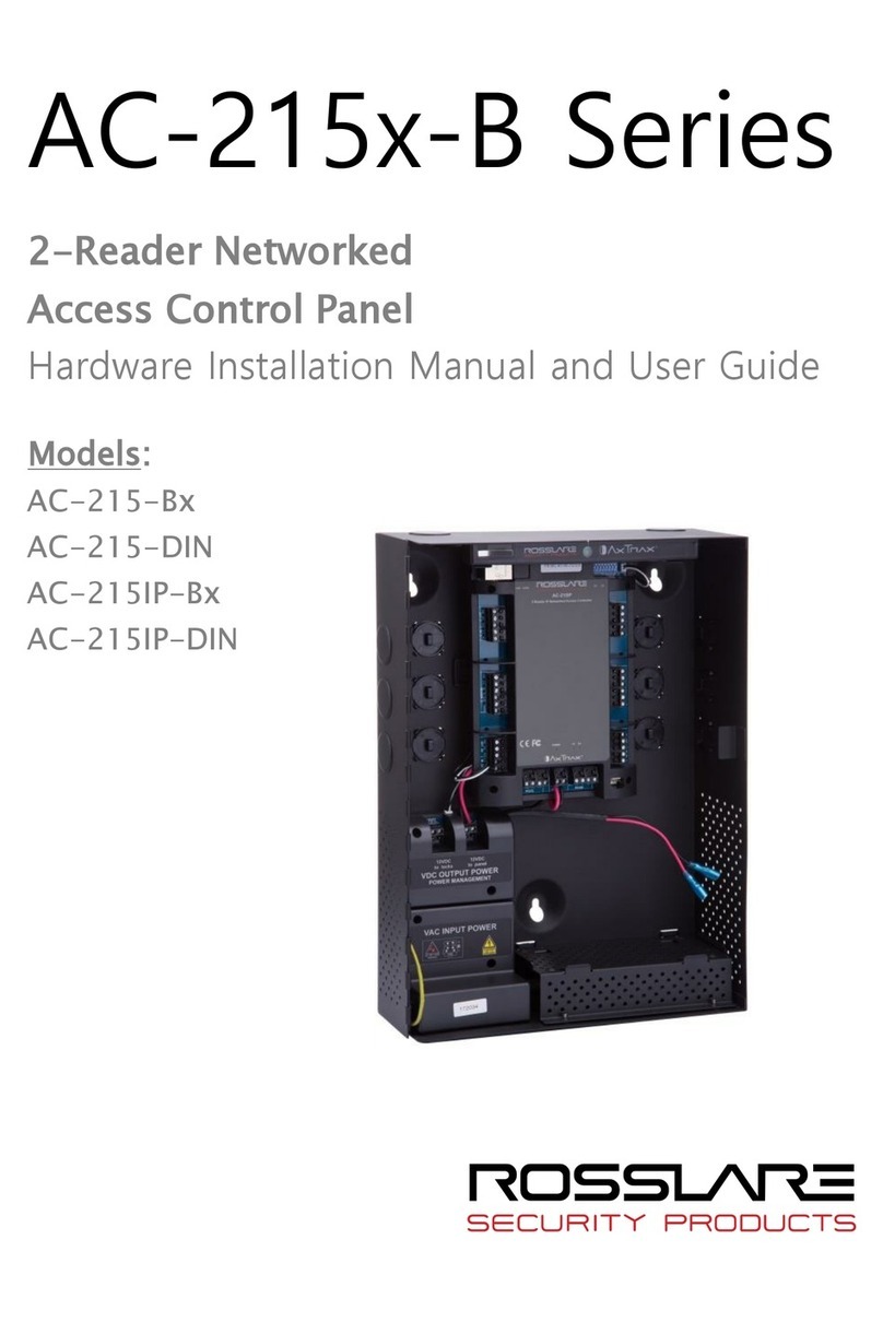
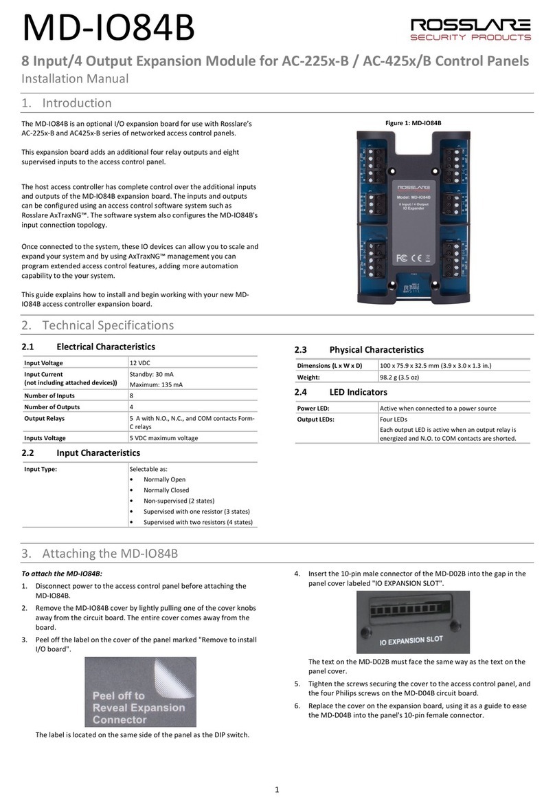
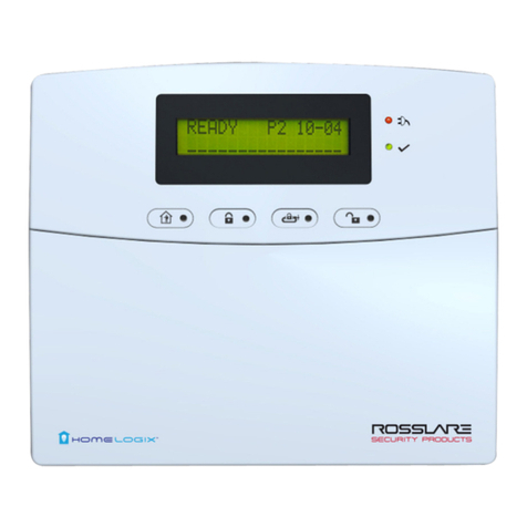
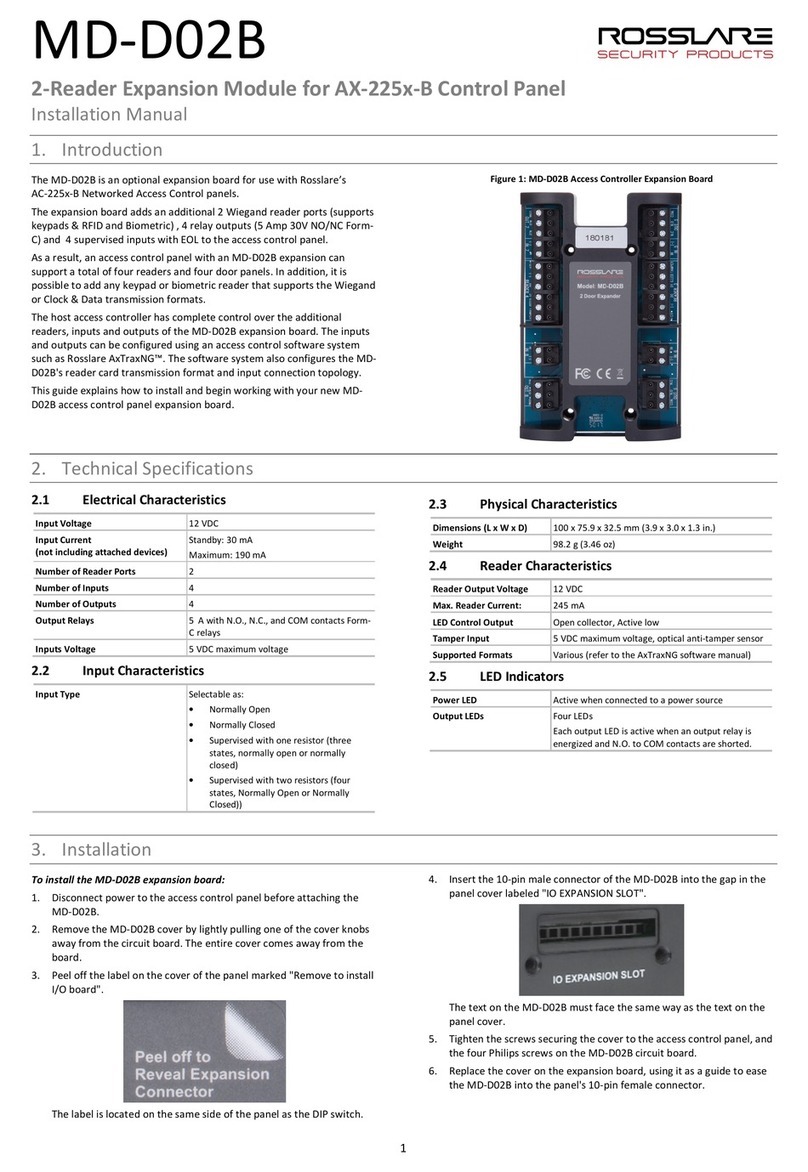
Rosslare AuraSys L-4 Assembly instructions

AuraSys™L-4
4-/8-Zone Alarm Panel
Hardware Installation Manual
Models:
L-4
L-4K
L-4PCBA

Copyright © 2012 by Rosslare. All rights reserved.
This manual and the information contained herein are proprietary to ROSSLARE
ENTERPRISES LIMITED and/or its related companies and/or subsidiaries’ (hereafter:
"ROSSLARE"). Only ROSSLARE and its customers have the right to use the information.
No part of this manual may be re-produced or transmitted in any form or by any means,
electronic or mechanical, for any purpose, without the express written permission of
ROSSLARE.
ROSSLARE owns patents and patent applications, trademarks, copyrights, or other
intellectual property rights covering the subject matter in this manual.
TEXTS, IMAGES, AND ILLUSTRATIONS INCLUDING THEIR ARRANGEMENT IN THIS
DOCUMENT ARE SUBJECT TO THE PROTECTION OF COPYRIGHT LAWS AND OTHER
LEGAL RIGHTS WORLDWIDE. THEIR USE, REPRODUCTION, AND TRANSMITTAL TO THIRD
PARTIES WITHOUT EXPRESS WRITTEN PERMISSION MAY RESULT IN LEGAL
PROCEEDINGS.
The furnishing of this manual to any party does not give that party or any third party any
license to these patents, trademarks, copyrights or other intellectual property rights,
except as expressly provided in any written agreement of ROSSLARE.
ROSSLARE reserves the right to revise and change this document at any time, without
being obliged to announce such revisions or changes beforehand or after the fact.

Table of Contents
AuraSys™ L-4 Family Installation Manual iii
Table of Contents
1. Introduction....................................................................... 9
2. Technical Specifications and Features .......................... 13
3. Installation and Wiring .................................................. 16
3.1 Installation Quick Guide.................................................................... 16
3.2 Installation Prerequisites.................................................................... 16
3.2.1 Preparing the Installation Environment ....................................................... 16
3.2.2 Preparing the Wiring ................................................................................. 16
3.2.3 Mounting the Control Panel....................................................................... 17
3.2.4 Installing the Keypad(s) .............................................................................. 22
4. Wiring Instructions ......................................................... 24
4.1 Wiring Quick Reference .................................................................... 24
4.2Wiring the System ............................................................................ 27
4.2.1 AC Wiring................................................................................................. 27
4.2.2 Battery Connection.................................................................................... 27
4.2.3 Telephone Wiring ...................................................................................... 28
4.2.4 Keypad and Expansion Wiring.................................................................... 28
4.2.5 PGM Connection....................................................................................... 28
4.2.6 Smoke Detector Connections..................................................................... 29
4.2.7 Zone Wiring .............................................................................................. 31
4.2.8 Sounder Connections ................................................................................ 34
4.3 Preliminary Testing............................................................................ 35
5. Programming via Keypad .............................................. 36
5.1 Keypad Quick Reference ................................................................... 36
5.1.1 Keypad User Functions............................................................................... 37
5.1.2 Indicator Bar.............................................................................................. 38
5.1.3 Numeric Programming Pad ........................................................................ 38
5.1.4 System Audio Feedback ............................................................................. 40
5.2 Access Level Types ............................................................................ 41
5.2.1 Master Programmer................................................................................... 41

Table of Contents
iv AuraSys™ L-4 Family Installation Manual
5.2.2 Installer Level............................................................................................. 41
5.2.3 User .......................................................................................................... 42
5.3 Entering Programming Mode (Installer/Master).................................. 42
5.4 Enable Installer Code Access ............................................................. 42
5.5 Installer Programming Level .............................................................. 42
5.5.1 Entering Parameters .................................................................................. 43
5.5.2 General Procedural Steps ........................................................................... 43
5.5.3 Programming Tables.................................................................................. 43
5.5.4 Advanced System Programming................................................................. 48
5.5.5 Zone Definitions – Advanced...................................................................... 50
5.5.6 Panel Setup............................................................................................... 52
5.5.7 CMS and Private Phone Reporting.............................................................. 52
5.5.8 PGM Setup................................................................................................ 55
5.5.9 System Timers ........................................................................................... 56
5.5.10 Wireless Device Enrollment/Deletion........................................................... 56
5.5.11 Remote Control Assignment ...................................................................... 58
5.5.12 Wireless Siren Definition ............................................................................ 58
5.5.13 Walk Test.................................................................................................. 59
5.5.14 System Time and Date ............................................................................... 59
5.5.15 Factory and Access Code Defaults .............................................................. 59
5.6 Master/User Access........................................................................... 59
5.6.1 User Codes................................................................................................ 59
5.6.2 Duress Code.............................................................................................. 60
5.6.3 Master User............................................................................................... 60
5.6.4 Users Authorization Setup ......................................................................... 60
5.6.5 System Time and Date ............................................................................... 60
5.6.6 Factory and Access Code Defaults .............................................................. 61
6. Programming via PC Software ...................................... 62
6.1 Connections ..................................................................................... 62
6.2 Software Programming Options ........................................................ 62
A. Expansions and Accessories........................................... 63
A.1 MD-31 (RJ-31X Jack)......................................................................... 63
A.2 SA-59 GSM Communicator............................................................... 64
A.3 XR-16A – Wireless Expansion ............................................................ 65
Table of Contents
AuraSys™ L-4 Family Installation Manual v
B. Reporting Codes.............................................................. 67
C. Battery Load Capacity .................................................... 69
D. Programming Worksheets ............................................. 70
D.1 Customer Information....................................................................... 70
D.2 Installer Information.......................................................................... 70
D.3 Device Information ........................................................................... 70
D.4 Zone Worksheet ............................................................................... 71
E. Declaration of Conformity............................................. 72
F. Limited Warranty ............................................................ 73

List of Figures
vi AuraSys™ L-4 Family Installation Manual
List of Figures
Figure 1: Rosslare L-4 Panel .......................................................................... 10
Figure 2: Rosslare L-4K Panel ........................................................................ 10
Figure 3: Rosslare L-4 PCBA Panel................................................................. 11
Figure 4: Rosslare L-4C, L-4CL, and L-4CU Panels ......................................... 11
Figure 5: Rosslare L-4D, L-4DL, and L-4DU Panels ......................................... 12
Figure 6: L-4 PCBA Panel Mounting Holes..................................................... 17
Figure 7: L-4C Mounting Template ............................................................... 18
Figure 8: L-4C Mounting .............................................................................. 19
Figure 9: L-4D Mounting Template ............................................................... 20
Figure 10: L-4D Mounting ............................................................................ 21
Figure 11: L-4/4K Drilling Template............................................................... 22
Figure 12: Keypad Mounting Dimensions Kx-04............................................ 23
Figure 13: L-4/L-4K Control Panel Components ............................................ 24
Figure 14: L-4 PCBA Control Panel Components and Dimensions.................. 25
Figure 15: L-4C Casing Wiring Threads......................................................... 26
Figure 16: L-4D Casing Wiring Threads......................................................... 27
Figure 17: Battery Connection Diagram ........................................................ 28
Figure 18: Telephone Diagram...................................................................... 28
Figure 19: PGM Wiring Diagram................................................................... 29
Figure 20: Smoke Detectors without Reset Mechanism ................................. 30
Figure 21: Smoke Detectors with Reset Mechanism ...................................... 31
Figure 22. Resistors ...................................................................................... 33
Figure 23: L-4/L-4K Sounder (bell) Connection.............................................. 34
Figure 24: KE-04 – MatrixBUS™ 4 Zone LED Keypad..................................... 36
Figure 25: KC-04 – MatrixBUS™ 4-Zone LCD Keypad ................................... 37
Figure 26: KD-04 – MatrixBUS™ 4-Zone Dot-Matrix Keypad ......................... 37
Figure 27: Numeric Keypad with Programming Icons .................................... 39
Figure 28: Rosslare's MD-62 TTL to RS-232 Converter................................... 62
Figure 29: MD-31 Dimensions ...................................................................... 63
Figure 30: MD-31 Internal Wiring ................................................................. 63
Figure 31: MD-31 to Alarm Panel Wiring ...................................................... 64
Figure 32: SA-59 Universal GSM communicator............................................ 65
Figure 33: XR-16A Wireless Expansion .......................................................... 66

List of Tables
AuraSys™ L-4 Family Installation Manual vii
List of Tables
Table 1: Hardwiring Schematics for Single Zone System ................................ 32
Table 2: Hardwiring Schematics for Doubled Zone System ............................ 32
Table 3: Resistor Color Scheme..................................................................... 34
Table 4: Resistors Provided ........................................................................... 34
Table 5: User Function Buttons ..................................................................... 37
Table 6: Operational Indicators ..................................................................... 38
Table 7: Programming Function Buttons ....................................................... 39
Table 8: Event Codes: Contact ID – Burglary and Fire .................................... 67
Table 9: Event Codes: Contact ID – Arming Events........................................ 67
Table 10: Event Codes: Contact ID – System Events ...................................... 67

Notice and Disclaimer
viii AuraSys™ L-4 Family Installation Manual
Notice and Disclaimer
This manual’s sole purpose is to assist installers and/or users in the safe and
efficient installation and usage of the system and/or product, and/or software
described herein.
Before attempting to install and/or use the system, the installer
and the user must read this manual and become familiar with all
safety requirements and operating procedures.
The system must not be used for purposes other than those for which it
was designed.
The use of the software associated with the system and/or product, if
applicable, is subject to the terms of the license provided as part of the
purchase documents.
ROSSLARE exclusive warranty and liability is limited to the warranty and
liability statement provided in an appendix at the end of this document.
This manual describes the maximum configuration of the system with the
maximum number of functions, including future options. Therefore, not
all functions described in this manual may be available in the specific
system and/or product configuration you purchased.
Incorrect operation or installation, or failure of the user to effectively
maintain the system, relieves the manufacturer (and seller) from all or any
responsibility for consequent noncompliance, damage, or injury.
The text, images and graphics contained in the manual are for the
purpose of illustration and reference only.
All data contained herein subject to change without prior notice.
In no event shall manufacturer be liable for any special, direct, indirect,
incidental, consequential, exemplary or punitive damages (including,
without limitation, any and all damages from business interruption, loss of
profits or revenue, cost of capital or loss of use of any property or capital
or injury).
All graphics in this manual are for reference only, some deviation between
the image(s) and the actual product may occur.
All wiring diagrams are intended for reference only, the photograph or
graphic of the PCB(s) are intended for clearer illustration and
understanding of the product and may differ from the actual PCB(s).

Introduction
AuraSys™ L-4 Family Installation Manual 9
1. Introduction
The AuraSys™ L-4 4/8-zone Security System family is a compact and advanced
4-zone (doubled) hardwired control panel for residential and light commercial
intrusion alarms.
There are several versions of the L-4 product:
L-4 – Arm Away, Arm Home, and Disarm using key switch
L-4K – Local arming using numeric keypad
L-4PCBA – PCB version that connects to external keypads
L-4C – PCB version incased in a Metal box with 220 VAC adaptor
L-4CL – PCB version incased in a Metal box with 110 VAC adaptor
L-4CU – PCB version incased in a Metal box without an AC adaptor
L-4D – PCB version incased in a specially designed Plastic box with 220
VAC adaptor
L-4DL – PCB version incased in a specially designed Plastic box with 110
VAC adaptor
L-4DU – PCB version incased in a specially designed Plastic box without an
AC adaptor

Introduction
10 AuraSys™ L-4 Family Installation Manual
Figure 1: Rosslare L-4 Panel
Figure 2: Rosslare L-4K Panel

Introduction
AuraSys™ L-4 Family Installation Manual 11
Figure 3: Rosslare L-4 PCBA Panel
Figure 4: Rosslare L-4C, L-4CL, and L-4CU Panels

Introduction
12 AuraSys™ L-4 Family Installation Manual
Figure 5: Rosslare L-4D, L-4DL, and L-4DU Panels

Technical Specifications and Features
AuraSys™ L-4 Family Installation Manual 13
2. Technical Specifications and
Features
The AuraSys L-4 family supports a wide range of security features. This section
lists the specifications for the features that comprise the security system, as
well as the electrical and mechanical specifications of the Security System.
General Attributes
Onboard dual EOL zone inputs
(+ tamper detection)
4
Zone doubling Yes
Max. supported zones 8
4-wire fire zone
(using PGM for reset)
1
Onboard PGM output 1 x OC 120 mA
Sounder output 1 x 1 Ampere
Onboard AUX outputs
L-4/L-4K
L-4PCBA
+12 VDC 1.0 Ampere
+12 VDC 1.7 Ampere
User codes 8 users, 1 Master, and 1 Installer
Nonvolatile event log size 256
Max. keypads supported
(KE-04, KC-04 and KD-04)
4
Central station accounts (primary,
secondary/backup)
Yes
Private telephone numbers Yes (3)
Wireless expansion supported Yes

Technical Specifications and Features
14 AuraSys™ L-4 Family Installation Manual
Electrical Characteristics
Power Supply Type Linear type (recommended)
Input Voltage L-4PCBA
16 VAC with 25 VA transformer
(14-18 VAC 50/60 Hz range)
24 VDC 1.2 A (20 to 30 VDC range)
L-4/L-4K
16 VAC with 20 VA transformer
(14-18 VAC 50/60 Hz range)
24 VDC 1A (20 to 30 VDC range)
Input Current L-4PCBA
Standby – 210 mA
Maximum – 600 mA
L-4/L-4K
Standby – 220 mA
Maximum – 720 mA
Battery (L-4/L-4K) BT-05
Type SLA (Sealed Lead Acid)
Voltage 12V
Capacity 800mAh
Backup/Recharge Period See table in Appendix C
Battery (L-4/L-4K) BT-16
Type NiMH (Nickel Metal Hydride)
Voltage 12 V
Capacity 2 Ah
Backup/Recharge Period See table in Appendix
C
Battery (L-4PCBA) OEM
Type SLA
Voltage 12 VDC
Capacity 5 Ah or 7Ah
Backup/Recharge Period See table in Appendix
C
Environmental Characteristics
Operating Environment Range Indoor use only
Operating Temperature Range -15°C to 44°C (5°F to 111.2°F)
Operating Humidity 0 to 95% (non-condensing)
RFI Protection > 20 V/m up to 1000 MHz
Supervision Tamper-proof system with constant supervision

Technical Specifications and Features
AuraSys™ L-4 Family Installation Manual 15
Mechanical Specifications
Dimensions
L-4PCBA
Height x Width
L-4, L-4K
Height x Width x Depth
L-4C, L-4CL, L-4CU
Height x Width x Depth
L-4D, L-4DL, L-4DU
Height x Width x Depth
165 x 65 mm
(6.5 x 2.6 in.)
130 x 170 x 38 mm
(5.1 x 6.7 x 1.5 in.)
254 x 255 x 92 mm
(10 x 10.04 x 3.62 in.)
374 x 286 x 109 mm
(14.72 x 11.26 x 4.29 in.)
Weight (without battery)
PCBA – 102 g (3.6 oz.)
L-4 – 290 g (10.2 oz.)
L-4K – 303 g (10.7 oz.)
L-4C – 2.50 kg (5.51 lb.)
L-4CL – 2.55 kg (5.62 lb.)
L-4CU – 1.92 kg (4.23 lb.)
L-4D – 2.20 kg (4.85 lb.)
L-4DL – 2.25 kg (4.96 lb.)
L-4DU – 1.62 kg (3.57 lb.)

Installation and Wiring
16 AuraSys™ L-4 Family Installation Manual
3. Installation and Wiring
This chapter provides steps for the installation of the AuraSys L-4 control panel
family, and the preliminary testing of the system. It includes a Quick Guide for
fast reference as well as complete programming and wiring instructions.
3.1 Installation Quick Guide
There are a number of steps to installing the unit:
Step Action Section
Preparing the Installation Environment 3.2.1
Preparing the Wiring 3.2.2
Mounting the Control Panel 3.2.3
Installing Keypads (Optional) 3.2.4
Wiring the L-4 System 4
3.2 Installation Prerequisites
Unit installation is limited to the control panel and to the keypads. Installation
instructions for expansion modules are included in appendices in this manual.
For information on installing the various detectors, please refer to the
individual manuals supplied with the detector.
3.2.1 Preparing the Installation Environment
Establish the control panel location using the following guidelines:
Locate the control panel in a place where the temperature is within the
specified limits for operation.
When distributing wiring, avoid putting the system wires close to house
wiring to reduce capacitive coupling of noise.
Locate the control panel in the center of the premises to avoid long runs
to any one location.
Install the panel 130 cm +/- 10 cm from the floor. Make sure to leave 15
cm all around the control panel for ventilation and/or wiring entry. The
panel should be installed at eye level to ease in making
connections/repairs.
3.2.2 Preparing the Wiring
The control panel provides 12 VDC up to either 1 Ampere for the L-4 and L-4K
or 1.7 Ampere for the L-4PCBA for add-ons (expansion modules) and sensors.

Installation and Wiring
AuraSys™ L-4 Family Installation Manual 17
The maximum wire length between the panel and accessories depends on the
amount of current drawn by the accessory and the gauge of the conductors
(wires) used.
The distance between the panel and the furthest keypad or add-on must not
exceed 200 meters due to the capacitance on the data line.
3.2.3 Mounting the Control Panel
The L-4 family of control panels requires mounting inside a secured enclosure,
such as a lockable metal or plastic box.
The L-4 family comes in several versions, with an enclosure and without:
L-4PCBA – no enclosure; adaptable for installation in customer-supplied
cabinet
L-4C - PCB version incased in a Metal box, comes in three models, with
220 adaptor for Europe, with 110 adaptor for Latin America, without
adaptor for US
L-4D - PCB version incased in a specially designed plastic box, comes in
three models, with 220 adaptor for Europe, with 110 adaptor for Latin
America, without adaptor for US
L-4 – plastic enclosure with a 3-state key switch
L-4K – plastic enclosure with a 6-button arming keypad
Follow the below instructions to mount the L-4 control panel family based on
the model you have.
To install the L-4PCB A panel:
1. Using the holes dimensions and locations shown in Figure 6, prepare the
mounting enclosure for the L-4 PCB board.
2. Carefully and securely attach the L-4 PCB board to the mounting
apparatus in the mounting enclosure.
3. Wire the panel according to the wiring instructions (see Chapter 4).
4. Close and secure the enclosure.
Figure 6: L-4 PCBA Panel Mounting Holes

Installation and Wiring
18 AuraSys™ L-4 Family Installation Manual
To install the L-4C panel:
1. Using the holes dimensions and locations shown in Figure 7, drill holes in
the wall.
2. Insert masonry anchors into the drilled holes.
3. Wire the panel according to the wiring instructions (see Chapter 4).
4. Mount the L-4C as shown in Figure 8.
5. Close and secure the enclosure.
Figure 7: L-4C Mounting Template

Installation and Wiring
AuraSys™ L-4 Family Installation Manual 19
Figure 8: L-4C Mounting
To install the L-4D panel:
1. Using the holes dimensions and locations shown in Figure 9, drill holes in
the wall.
2. Insert masonry anchors into the drilled holes.
3. Wire the panel according to the wiring instructions (see Chapter 4).
4. Mount the L-4D as shown in Figure 10.
5. Close and secure the enclosure.

Installation and Wiring
20 AuraSys™ L-4 Family Installation Manual
Figure 9: L-4D Mounting Template
Other manuals for AuraSys L-4
1
This manual suits for next models
2
Table of contents
Other Rosslare Control Panel manuals

Rosslare
Rosslare HLX-24TH Series User manual

Rosslare
Rosslare HLX-40 Assembly instructions

Rosslare
Rosslare AC-225-B Series Manual

Rosslare
Rosslare AC-020 User manual

Rosslare
Rosslare AC-425x-B Series User manual

Rosslare
Rosslare MD-D02B User manual

Rosslare
Rosslare AC-215-Bx Guide

Rosslare
Rosslare AC-425-B User manual

Rosslare
Rosslare AC-425IP-BU User manual

Rosslare
Rosslare MD-IO84B User manual