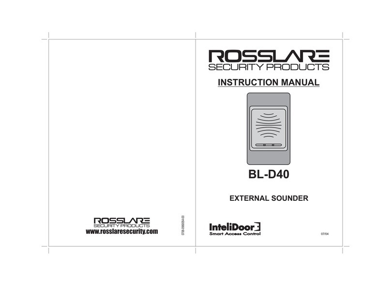
BL-D40
External Sounder
Installation Manual
1
1. Introduction
The BL-D40 External Sounder is compatible with the AC-x31, ACx32,
AC-x41, and AC-x42 series of standalone controllers. It is designed to
operate indoors and is installed within the premises. The sounder can
be powered by 16 VAC or by a 12–24 VDC power supply.
The BL-D40 is capable of emitting four different types of alerts both
audible and visual –Bell, Door Chime, Siren, and Strobe Light.
The bell always sounds when the controller's doorbell button is
pressed.
The door chime can be programmed to sound whenever the
controller unlocks the door. The door chime does not sound when
the REX button is used to open the door.
The siren can be programmed to sound when the case of the
controller is opened or when the controller is removed from the
wall. The controller can also program the length of the siren.
The LED on the BL-D40 turns on when there is a bell or door
chime. If there is a siren, it flashes as long as the tamper switch is
activated or opened.
The controller communicates with the BL-D40 using a coded
proprietary Rosslare communications protocol. This provides a more
secure link between the controller and the BL-D40. If the BL-D40
receives any unrecognized codes on its communication line or
communication between the controller and the BL-D40 is severed, the
strobe flashes repeatedly until the communication problem is resolved.
Figure 1: BL-D40
2. Technical Specifications
2.1 Electrical Characteristics
Maximum Input Current
(@12 V)
Standby: 11 mA
Max: 100 mA
16 VAC from a transformer
12 to 24 VDC from a regulated power
supply (linear type recommended)
Three types of audible output:
2.2 Environmental Characteristics
Operating Temperature Range
-31°C to 63°C (-25°F to 145°F)
0 to 95% (non-condensing)
2.3 Physical Characteristics
122 x 75 x 24 mm (4.8 x 3.0 x 0.9 in.))
3. Installation
3.1 Installation with a Controller
The BL-D40 should be located nearby the door and controller it is to be
attached to, where it can be heard, and where the strobe can be seen.
The BL-D40 is designed to be easily mounted to a US Gang Box.
To install the BL-D40 with a controller:
1. Remove the bezel screw (Figure 2).
Figure 2: BL-D40 Layout
2. Screw the BL-D40 onto a US Gang Box through the two mounting
holes provided (Figure 2).
3. Wire the BL-D40 terminal blocks as shown in Figure 3.
Figure 3: Wiring to a Controller
It is recommended that 22 Gage wire be used between the BL -
D40 and the controller.
4. Replace the BL-D40 bezel and replace the factory default screw
with the security screw that is provided in the installation kit.


