manuals.online logo
Brands
  1. Home
  2. •
  3. Brands
  4. •
  5. Rotary
  6. •
  7. Lifting System
  8. •
  9. Rotary E Series User manual

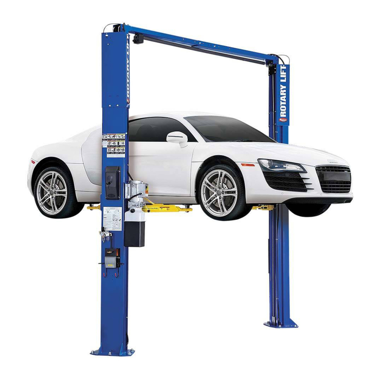
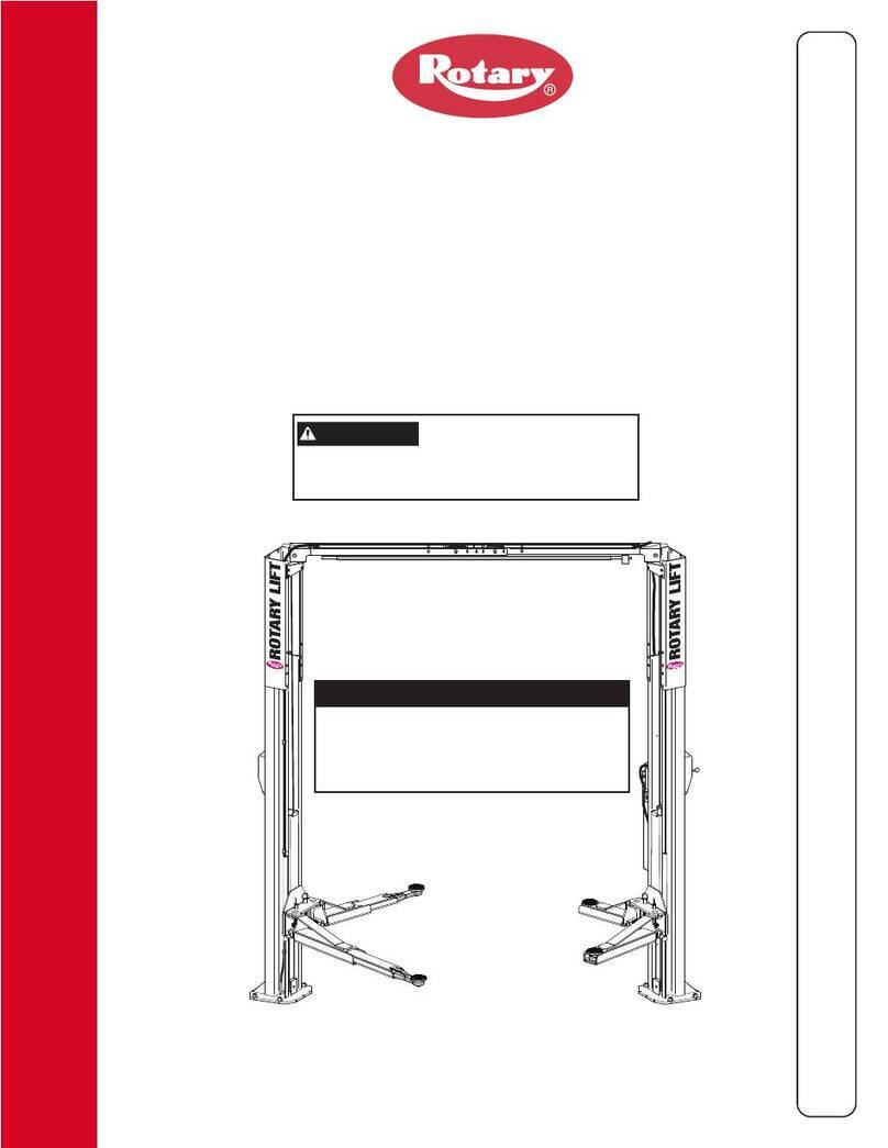
Rotary E Series User manual

INSTALLER: Please return this booklet to literature package and give to lift owner/operator.
O
P
E
R
A
T
I
O
N
&
M
A
I
N
T
E
N
A
N
C
E
M
A
N
U
A
L
O
P
E
R
A
T
I
O
N
&
M
A
I
N
T
E
N
A
N
C
E
M
A
N
U
A
L
OM20155
© January 2004 by Rotary Lift. Rev. -- 1/6/2004
TLO7E
E, M, And iSeries
(500 Series)
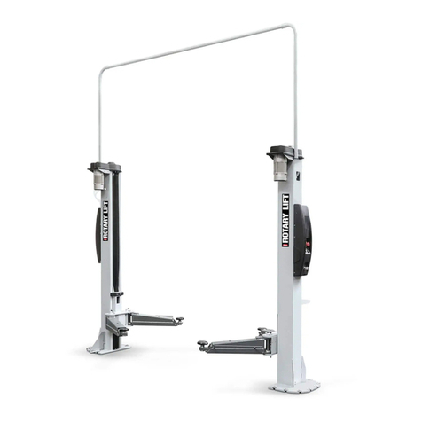
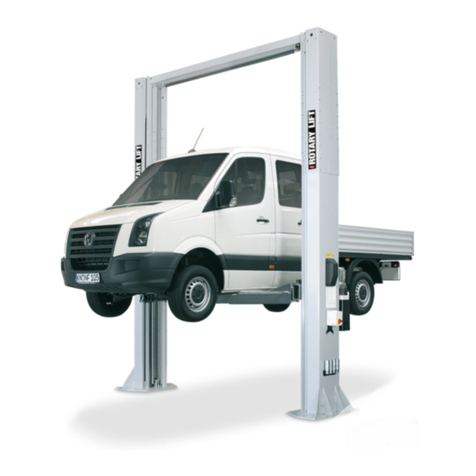
Two Post Surface Mounted Lifts
Capacity: 3,100kg (775 kg per arm)
Rheinland
TUV
TUV
LP20198
Table of Contents
Safety Instructions ............................................................................. 2
Lift Controls ........................................................................................ 3
Operating Instructions ....................................................................... 5
Maintenance Instructions .................................................................. 8
Trouble Shooting ................................................................................ 9
Latch Cable Adjustment .................................................................... 18
Manual Lowering Instructions .......................................................... 19
2
Display this manual in a conspicuous location
in the lift area convenient to the operator.
Only those technicians who have been properly trained in the usage
and care of the lift should be allowed to operate the lift.
Local regulations MAY require that the trained operator be at least
18 years of age or be supervised by a trained operator while:
A. positioning the vehicle in the service bay,
B. positioning the lifting devices, and,
C. actuating the lift controls.
ALWAYS lift the vehicle using all lifting devices together.
NEVER raise just one end, one corner, or one side of
the vehicle.
ONLY lift vehicles which have an individual axle weight that
does not exceed one-half the lift capacity. See load capacity
table below.
The lift is to be used for raising unoccupied
motor vehicles ONLY!
MODEL LOAD CAPACITY
TLO7E
1100kg FOR 3-WHEEL VEHICLES
2300kg FOR 4-WHEEL VEHICLES
3
DOWN
OFF SAFETY
DISTANCE
ALARM
View "A-A"
A
A
Warning Control Box
Lowering Switch
E-Stop Disconnect
Raise Switch
Fill-Breather Cap
Safety Latch
Release Handle
1
5
4
3
2
Lift Controls M Series Lifts
Fig. 1
Lift Controls
1 Turning Key to the right provides electricity to the motor.
2 Pushing button starts the motor and raises the arms.
3 Pulling handle down disengages safety latches.
4 Remove cap to fill or add fluid to power unit tank.
5 Turning Knob Lowers Lift.
4
00/00/00 00:00
FF
1ON
Slave Control Panel Only Runs The
Lift - You Can Not Select Any Menus
From The Slave Side.
5 Menu Selection / Lower To Locks
FF
1ON
2 Raise Lift 4 Mode Button
5 Lower To Locks
3 Lower Lift Touch Pad
Touch Pad
1 Disconnect
Switch
Tab Can Be
Pulled Out
Of Switch To
Lock Disconnect
In OFF Position
Lift Controls For:
E Series Lifts
1 Turning disconnect switches provides electircity to motor.
Note: Both disconnect switches must be "ON" to provide
electricity to motor.
2 Raises lift.
3 Lowers lift.
4 Resets the lift.
5 Lowers lift to locking latches.
Note: Press to raise lift off of locking latches then press
to lower lift.
Lift Controls For:
iSeries Lifts
1 Turning disconnect switch provides electircity to motor.
Note: Both disconnect switches must be "ON" to provide
electricity to motor.
2 Raises lift and scrolls up through menu selections.
3 Lowers lift and scrolls down through menu selections.
4 Toggles operator between menu selection and lift operation.
5 Lowers lift to locking latches.
Note: Press to raise lift off of locking latches then press
to lower lift.
1 Disconnect
Switch
Tab Can Be
Pulled Out
Of Switch To
Lock Disconnect
In OFF Position
2 Raise Lift / Scroll Up
3 Lower Lift / Scroll Down
4 Mode Button
Fig.1a
5
OPERATING INSTRUCTIONS
Surface Mounted Frame Engaging Lifts
To avoid personal injury and/or property damage, permit only trained personnel to
operate lift. After reviewing these instructions, get familiar with lift controls by running
the lift through a few cycles before loading vehicle on lift.
IMPORTANT Always lift the vehicle using all lifting devices. NEVER
raise just one end, one corner, or one side of vehicle.
Assure overhead bar will contact highest point on the vehicle.
1. Before Loading:
• Inspect Lift - See "Operator Maintenance" on page
8. Never operate if lift malfunctions or has broken
or damaged parts.
• Lift must be fully lowered and service bay clear of
all personnel before the vehicle is positioned onto
lift.
• Position rear ramp and front forks so that they match
vehicle wheel base and are centered on columns.
• Assure area around lift is free of tools, debris,
grease, and oil.
• Assure Forks and Ramp are free from grease and oil.
• Do Not allow unauthorized persons in shop area
while lift is in use.
• Do Not use any part of the lift as a crane or as a
support for another lifting mechanism. (i.e.: block
& tackle, etc.)
• Retract forks to give widest drive through.
• For M Series Lifts, turn key switch to "ON"
Position.
2. Loading:
• Do Not allow unauthorized or untrained persons to
position vehicle or operate lift.
• Do Not overload lift. See capacity label on lift.
• Position vehicle with the rear wheels centered on the
rear ramp. (Driving over forks is permitted with
wide vehicles).
• Move forks so the front wheels are fully cradled.
• Use small wheel adapter on forks when necessary,
see Fig. 2.
• For 3-wheel vehicles, center single wheel on rear
ramp.
3. To Raise Lift:
• Do Not permit anyone on lift or inside vehicle when it
is being raised (or lowered).
• Maintain visual contact with pickup points and
vehicle throughout the motion of the lift while
remaining clear of lift.
• For M Series Lifts, push RAISE switch on power
unit, Fig. 1. For E & iSeries lifts, push
button on touchpad of master or slave control panel,
Fig. 1a.
Note: Allow 2 seconds between motor starts. Failure to
comply may cause motor burnout.
• Raise vehicle until tires clear the floor.
• Stop and check for stable contact with vehicle.
• Continue to raise to desired height only if vehicle is
stable on lift.
• Lower lift onto safety latches after desired height is
reached. (Lift is to be raised high enough for locking
latches to engage.) For M Series lifts, turn lowering
switch to DOWN position, Fig. 1. For E and i Series
lifts, push
SELECT
LOWER TO LOCKS
on touchpad of either master
or slave control panel.
• Repeat complete spotting, loading, and raising
procedures if vehicle is unstable.
WARNING
6
RESIDUAL RISKS
• Check tire inflation and attachment to axles to assure proper fit on
lifting attachments of lift.
• Vehicles with heavy accessories attached, will have a changed center
of gravity. Use stands when working on such vehicles.
• Assure lawn mower attachments do not cause either individual axle
weight to exceed one half lift capacity.
CAUTION
Use small wheel adapter kit when raising
vehicles with less than 13” wheels. Be sure to engage
dowel screw.
Fig. 2
4. While Using Lift:
• Avoid excessive rocking of vehicle while on lift.
• Avoid accidental touching of exposed exhaust system on
raised vehicles. Watch for air hoses and electrical cords
which may be tripped over.
• Wear safety glasses while working under vehicle.
5. Before Lowering Lift:
• Remove all tools or other objects from lift area.
• Assure personnel are not in lift area.
6. To Lower Lift:
• Remain clear of lift when lowering vehicle. Keep Feet
Clear!
• Raise lift off locking latches. For M Series lifts, push
raise button, Fig. 1. For E and iSeries lifts, push
on master or slave side control panel.
• For M Series, Actuate LATCH release handle fully and
hold. Push LOWERING switch to DOWN position, Fig.
1a. When lift stops, turn lowering switch to SAFETY
DISTANCE position while keeping feet clear.
Note: Both LATCH release and LOWERING switch are
deadman-type design. Each must be held down to lower lift.
Do not override these self-closing lift controls.
• For E and iSeries lifts push on master or
slave control panel.
7 Unloading:
• Assure lift is fully lowered.
• Retract forks as far as possible.
• Assure Exit area is clear of objects and personnel before
removing vehicle from lift.
8. Power Off:
• For M Series, turn key switch to "OFF" position while lift is
not in use.
• Remove key when leaving the lift unattended.
9. Trouble Shooting:
• See page 7.
10. Maintenance:
• See page 7.
7
•Always keep bolts tight. Check periodically.
•Always keep lift components clean.
•Always, if oil leakage is observed, call local service repre-
sentative.
•Daily: Check cables and sheaves for wear. If parts are
worn, call local service representative.
•Daily: Inspect lifting devices for damage or excessive wear.
If parts are worn, call local service representative.
• Daily: Check for permanent deformation to the latches. If
present, call local service representative to replace parts.
•Monthly: Check equalizer cable tension. If parts are worn,
call local service representative.
•Monthly: Check overhead switch for function.
•Every 3 Months: Check anchor bolts for tightness. Anchors
should be torqued to 122Nm (12.4kg-m).
•Every 6 months: Check fluid level of lift power unit and
refill to proper level in level indicator with lift fully lowered.
•Replace all decals on the lift if unable to read or missing.
Reorder labels from Rotary Lift.
•Monthly: Clean and check base of lift. Remove any rust and
touch-up with paint.
•Monthly: Coat the cable contact surface with a light grease
such as "TUFOIL".
OPERATOR INSPECTION & MAINTENANCE
(MAINTENANCE AUTHORIZED BY OPERATOR)
Cause
1. Blown fuse or circuit breaker.
1. Low oil level.
1. Overloading lift.
See Remedy
See Remedy
See Remedy
See Remedy
See Remedy
See Remedy
Remedy
1. Replace blown fuse or reset circuit
breaker.
2. Contact service representative for
further assistance.
1. Fill tank to MIN___ mark with
ISOVG32 hydraulic oil or
DexronIII ATF.
2. Contact service representative for
further assistance.
1. Check vehicle weight and/or bal-
ance vehicle weight on lift.
2. Contact service representative for
further assistance.
1. Contact service representative for
further assistance.
1. Contact service representative for
further assistance.
1. Contact service representative for
further assistance.
1. Contact service representative for
further assistance.
1. Contact service representative for
further assistance.
1. Contact service representative for
further assistance.
Trouble
Motor does not run.
Motor runs but will not raise lift.
Motor runs—raises unloaded lift
but will not raise vehicle.
Lift slowly settles down.
Slow lifting speed or oil blowing
out filler breather cap.
Lift going up unlevel.
Anchors will not stay tight.
Locking latches do not engage.
Locking latches do not disengage.
TROUBLE SHOOTING FOR OPERATORS
FOR M SERIES LIFTS
8
Cause
1. Overhead Sensor Fault
1. Touch pad not functioning.
1. Incorrect voltage to power unit.
1. Overloading lift.
1. Broken latch spring.
Remedy
1. Check sensor for contact with
vehicle.
1. Check touchpad on opposite column
if neither touchpad is functioning
contact service representative for
further assistance.
1. Contact service representative for
further assistance.
1. Check vehicle weight and/or balance
vehicle weight on lift.
2. Contact service representative for
further assistance
1. Contact service representative for
further assistance.
Trouble
Error message on LCD.
No error message on LCD.
Motor won't run from either
column.
Motor runs but will not raise lift.
Locking latches do not engage.
TROUBLE SHOOTING FOR OPERATORS
FOR iSERIES LIFTS
Up button pressed but lift doesn't raise
Down button pressed but lift doesn't lower
Cause
1. LOWERING VALVE CIRCUIT
FAULT
2. Latch Release Fault 1
3. Latch Release Fault 2
1. Touchpad not functioning
Remedy
1. Check lowering valve plug on power
unit. If connection is good and you
are still getting this error
contact service representative for
further assistance.
2. Solenoid failure master control
panel side. Contact service repre-
sentative for further assistance.
3. Solenoid failure slave control panel
side. Contact service representative
for further assistance.
1. Contact service representative for
further assistance.
Trouble
Error message on LCD.
No error message on LCD.
9
Trouble
Error message on LCD
No error message on LCD
Cause
1. LOWERING VALVE CIRCUIT
FAULT
1.Touchpad not functioning
Remedy
1. Check lowering valve plug on
power unit. If connection is good
and you are still getting this error
contact service representative for
further assistance.
1. Check touchpad on opposite
column if neither touchpad is
functioning contact service
representative for further assis-
tance.
TROUBLE SHOOTING FOR OPERATORS
FOR iSERIES LIFTS
Lower To Locks
SELECT
LOWER TO LOCKS
button pressed but lift doesn't lower
Cause
1. Overhead Sensor Fault
1. Touch pad not functioning.
1. Incorrect voltage to power unit.
1. Overloading lift.
1. Broken latch spring.
Remedy
1. Check sensor for blockage
1. Check touchpad on opposite column
if neither touchpad is functioning
contact service representative for
further assistance.
1. Contact service representative for
further assistance.
1. Check vehicle weight and/or bal-
ance vehicle weight on lift.
2. Contact service representative for
further assistance
1. Contact service representative for
further assistance.
Trouble
9 signals.
Press button nothing
happens
Motor won't run from either
column.
Motor runs but will not raise lift.
Locking latches do not engage.
TROUBLE SHOOTING FOR OPERATORS
FOR E SERIES LIFTS
Up button pressed but lift doesn't raise
10
TROUBLE SHOOTING FOR OPERATORS
FOR E SERIES LIFTS
Down button pressed but lift doesn't lower
Cause
1. LOWERING VALVE CIRCUIT
FAULT
1. Latch Release Fault 1
1. Latch Release Fault 2
1. Touchpad not functioning
Remedy
1. Check lowering valve plug on
power unit. If connection is good
and you are still getting this error
contact service representative for
further assistance.
1. Solenoid failure master control
panel side. Contact service
representative for further
assistance.
1. Solenoid failure slave control
panel side. Contact service
representative for further
assistance.
1. Check touchpad on opposite
column if neither touchpad is
functioning. Contact service
representative for further
assistance.
Trouble
6 signals.
7 signals.
8
signals.
Press button nothing
happens.
Trouble
Press
SELECT
LOWER TO LOCKS
button nothing
happens.
6 Signals
Cause
1. Touchpad not functioning
1. Bad Circuit Board
Remedy
1. Check touchpad on opposite
column if neither touchpad is
functioning.
Contact service representative for
further assistance.
1. Contact service representative for
further assistance.
Lower To Locks
SELECT
LOWER TO LOCKS
button pressed but lift doesn't lower
11
Inspection Points
REPAIR MAINTENANCE
(MAINTENANCE AUTHORIZED BY QUALIFIED SERVICE REPRESENTATIVE ONLY)
Aside from the routine checks that are stated under "Operator Maintenance", the following
annual inspection is to be performed and a record of this inspection permanently retained on
site. All deficiencies are to be corrected by the proper authorized personnel.
Annual Inspection
(performed by Authorized Personnel)
•Lockout any energy sources before beginning any repairs.
• DO NOT modify the lift in any manner without the prior
written consent of the manufacturer.
•If electrical problems develop, make repairs according to
local electrical codes. Use genuine Rotary Lift parts when
replacement is necessary.
• Replace worn parts as required with genuine
Rotary parts.
• Adjust equalizer cable tension per lift installation
instructions.
• Monthly: Lubricate locking latch shafts. Push latch
handle several times for oil to penetrate joints.
• Check accessibility of the operating procedures.
• Check accessibility and readability of all labels.
• Check the rated load capacity of the lift.
• Examine all structural components including welds.
• Check electrical cords for insulation damage.
• Check fluid level.
• Check the lift controls for function.
• Check all fastening devices for tightness including floor anchor bolts.
• Check exposed surfaces and edges.
• Operate the lift and check the operation of the positive stop and the lift safety latches.
• Check for proper operation of lifting devices.
• With a representative vehicle on the lift, check the lowering speed (not to exceed 0.15m/s).
• Check the operation of the synchronization or equalization system so that both sides raise and lower equally.
• *Check the function of overhead switch and/or overhead sensors (Overhead sensors only on E and i series lifts).
• Check all accessible piping, tubing, hose, valves and fittings. Review lift oil consumption records.
• *Operate lift through full excursion and observe.
• With lift loaded, stop the lift at midpoint of travel and observe for drifting down and hydraulic leaks.
• Check with operator to ascertain any unusual operating characteristics.
*Perform check with and without a vehicle representative load.
12
TROUBLE SHOOTING FOR AUTHORIZED MAINTENANCE PERSONNEL
FOR ALL Series Lifts
Cause
1. Incorrect voltage to motor.
2. Bad wiring connections.
3. Motor up switch burned out.
4. Overheadlimitswitchburnedout.
5. Motor windings burned out.
1. Overloading lift
2. Motor running on low voltage
3. Debris in lowering valve
4. Pump sucking air
5. Suction stub off pump
6. Low oil level
7. Improper relief valve adjustment
1. Debris in check valve seat.
2. Debris in lowering valve seat.
3. External oil leaks.
1. Air mixed with oil.
2. Air mixed with oil suction.
3. Oil return tube loose.
1. Equalizercablesoutofadjustment.
2. Lift installed on unlevel floor.
1. Holes drilled oversize.
2. Concrete floor thickness or
holding strength not sufficient.
1. Latch shafts rusted. (Usually
occurs on outside installations or
in high humidity areas such as
vehicle wash bays.)
1. Latch cable is broken.
2. Cable is off sheaves.
3. Latch cable is loose.
Remedy
1. Supply correct voltage to motor.
2. Repairandinsulateallconnections.
3. Replace switch/touchpad.
4. Replace switch/overhead sensor/
reflector.
5. Replace motor.
1. Check vehicle weight and/or
balance vehicle weight on lift
2. Supply correct voltage to motor
3. Clean lowering valve
4. Tighten all suction line fittings
5. Replace suction stub
6. Fill tank to proper level with
ISOVG32 hydraulic oil or Dexron
III ATF
7. Replace relief valve cartridge
1. Clean check valve.
2. Clean lowering valve.
3. Repair external leaks.
1. Change oil to Dexron III ATF
or ISOVG32.
2. Tighten all suction line fittings.
3. Reinstall oil return tube.
1. Adjust equalizer cables to correct
tension.
2. Shim lift to level columns (Not to
exceed 13mm). If over 13mm,
break out floor and level per lift
installation instructions.
1. Relocate lift using new bit to drill
holes. Reference installation
instructions for proper anchoring
method and minimum spacing
requirements.
2. Break out old concrete and re-
pour new pads for lift per lift
installation instruction.
1. Remove covers, oil latch mecha-
nism. Depress latch release
handle several times to allow oil
to coat shaft.
1. Replace cable.
2. Check position of upper sheaves.
3. Replace cable.
Trouble
Motor does not run.
Motor runs but will not raise lift
Lift slowly settles down.
Slow lifting speed or oil blowing out
filler breather cap.
Lift going up unlevel.
Anchors will not stay tight.
Locking latches do not engage.
(M Series lifts only)
Locking latches do not disengage.
(M Series lifts only)
Note: Shim thickness of 51mm is possible by using optional shim kit #FC5393. Contact your authorized Rotary
repair person.
13
Trouble
Error message on
LCD
No error message on LCD
Locking latches will not engage
Cause
1. Overhead Sensor Fault
2. Power unit circuit fault
1. Touchpad not functioning
1. Broken latch spring
Remedy
1. Check sensor for contact with
vehicle.
2. Have certified electrician check
wiring to power unit.
1. Replace touchpad.
1. Replace latch spring
TROUBLE SHOOTING FOR AUTHORIZED MAINTENANCE PERSONNEL
FOR iSeries Lifts
Up button pressed but lift doesn't raise
Trouble
Lift stops short of full rise or
chatters.
Cause
1. Low oil level
2. Air in hydraulic lines/cylinder
Remedy
1. Fill tank to MIN___ mark with
ISOVG32 hydraulic oil or
DexronIII ATF.
2. Start unit, raise lift about
610mm. Open cylinder bleeders
approximately 2 turns. Close
bleeders when fluid streams.
Lower lift and fill tank.
TROUBLE SHOOTING FOR AUTHORIZED MAINTENANCE PERSONNEL
FOR ALL Series Lifts
14
TROUBLE SHOOTING FOR AUTHORIZED MAINTENANCE PERSONNEL
FOR iSeries Lifts
Down button pressed but lift doesn't raise
Trouble
Error message on LCD
No error message
on LCD
Cause
1. LOWERING VALVE CIRCUIT
FAULT
2. Latch Release Fault 1
3. Latch Release Fault 2
1. Touchpad not functioning
Remedy
1a. Replace lowering valve.
1b. Check lowering valve plug.
2. Faulty solenoid or faulty connec-
tion on master control panel side.
Replace components.
3. Faulty solenoid or faulty connec-
tion on slave control panel side.
Replace components.
1. Replace touchpad.
Lower To Locks
SELECT
LOWER TO LOCKS
button pressed but lift doesn't lower
Trouble
Error message on LCD
No error message on LCD
Cause
1. LOWERING VALVE CIRCUIT
FAULT
1. Touchpad not functioning
Remedy
1a. Replace lowering valve.
1b. Check lowering valve plug.
1. Replace touchpad.
15
Trouble
9 Signals.
Press button nothing
happen
Locking latches will not engage
Cause
1. OVERHEAD SENSOR HAS
BEEN TRIPPED
2. Power unit circuit fault
1. Touchpad not functioning
1. Broken latch spring
Remedy
1. Check sensor for contact with
vehicle.
2. Have certified electrician check
wiring to power unit.
1. Replace touchpad.
1. Replace latch spring
TROUBLE SHOOTING FOR AUTHORIZED MAINTENANCE PERSONNEL
FOR E Series Lifts
Up button pressed but lift doesn't raise
16
TROUBLE SHOOTING FOR AUTHORIZED MAINTENANCE PERSONNEL
FOR E Series Lifts
Trouble
6 Signals
7 Signals
8 Signals
Press button nothing
happens
Cause
1. LOWERING VALVE CIRCUIT
FAULT
1. Latch Release Fault 1
1. Latch Release Fault 2
1. Touchpad not functioning
Remedy
1. Replace lowering valve.
2. Check lowering valve plug.
1. Faulty solenoid or faulty connec-
tion on master control panel side.
Replace components.
1. Faulty solenoid or faulty connec-
tion on slave control panel side.
Replace components.
1. Replace touchpad
Down button pressed but lift doesn't lower
Lower To Locks
SELECT
LOWER TO LOCKS
button pressed but lift doesn't lower
Trouble
Press
SELECT
LOWER TO LOCKS
button nothing
happens
6 Signals
Cause
1. Touchpad not functioning
1. Bad circuit board.
Remedy
1. Replace Touchpad.
1. Replace circuit board.
17
Shoulder Bolt
Cable Clamp
Feed cable up through Cable
Clamp, loop over end of
shoulder bolt and feed back
down through Cable Clamp.
(2) 3/8" Retaining
Rings
Latch Cable Sheave
Latch Cable Conduit Guide
Right Column
Latch Cable
Notice the clearance
removed between
Control Plate Slot
and Latch Dog Pin.
Checking and Adjusting Equalizer Cables:
Raise lift to check equalizer cable tension. Below
carriage, grasp adjacent cables between thumb and
forefinger, with about 67N effort you should just pull the
cables together. Adjust at upper tie-offs (Fig. 5).
Latch Cable Adjustment For M Series Lifts
Upper Cable Tie Off
& 5/8" Nylon Insert
Locknut
Lower Cable Tie Off
& 5/8" Nylon Insert
Locknut
5/16-18NC x 3/8" lg. BHMS
Latch handle MUST be
positioned at the top of slot in
the latch control cover.
Checking and Adjusting Locking Latch Cable:
1. Raise carriages past the first latch position and then
lower onto latches.
2. Check that the latches have fully engaged when the
latch handle is released. Be sure carriage is resting on
latch dog.
3. Raise carriages fully off latches, push latch handle and
check that the latches have fully disengaged.
4. Make necessary adjustments if required, see Fig. 7,
recheck latch function. Latch handle must be as shown in
Fig. 8.
Pull Control Plate down, making sure the Latch Dog
itself does not move, to eliminate clearance between
Control Plate slot and Latch Dog pin (Fig. 6). Loosen
clamp and remove slack in the cable. Tighten the clamp.
Fig. 6
Fig. 7
Fig. 8
Fig. 5
18
MANUAL LOWERING OF LIFT
If your lift is in a raised position and you
lose power it is important to know how to
lower the lift manually. Make sure
nothing is under the lift and all unautho-
rized personnel are away from the lift area.
1.) Place a hydraulic jack and pipe under
the carriage on the master control side.
Jack should be rated to lift the capacity of
the vehicle.
2.) Raise lift off of the locking latch. You
should only have to raise lift approxi-
mately 2mm to disengage the lock.
3.) Remove access panel from the master
control panel (slave control panel for step
6) and pull locking latch back, Fig. 9. If
you can't pull it back with your fingers
then you don't have the latch off of the
lock. Repeat step #2 until lock is
disengaged.
4.) Place a flat piece of steel behind latch
dog and back of column to keep it off of
the lock.
5.) Slowly lower hydraulic jack and pipe
out from under the arm carriage.
6.) Repeat procedures 1 through 5 on slave
control panel column.
7.) The lift is now being held up by
hydraulics at this point
8.) Remove cap from lowering valve and
press to lower lift, Fig. 9. The lift will
lower at a slow speed. Replace cap on
lowering valve after lift has been lowered.
9.) If your facility lost power your lift will
operate when you regain power.
10.) If your facility power was not lost
have a certified electrican check wiring to
lift or call an authorized service represen-
tative
For E and iLifts Only
Access Panel
Pull Back
Locking Latch
Push
Lowering
Valve
Remove Cap
Fig. 9
19
EC Declaration of Conformity to Type
Manufacturer’s Name .................... Rotary Lift/Dover Corporation
Manufacturer’s Address .................... 2700 Lanier Drive
Madison, Indiana 47250 USA
Representative’s Name .................... John Uhl
Representative’s Address .................... Rotary Lift
2700 Lanier Drive
Madison, Indiana 47250 USA
Type of Equipment .................... Hydraulic Automotive Lift
Model Numbers .................... TLO7E (E, M, & iSeries)
Relevant Directives .................... 98/37/EC
Approval Body .................... TÜV Rheinland
Certificate Number .................... BM 60002498 0001
I, the undersigned, hereby declare that the
equipment specified above conforms with the
type-tested sample certified by the Approval
Body stated above.
Place: Madison, Indiana, USA
_____________________________________
(Signature)
ENGINEERING MANAGER
Trained Operators and Regular Maintenance Ensures
Satisfactory Performance of Your Rotary Lift.
Replacement Parts: See installers package for parts breakdown sheet.
Order Genuine Rotary replacement parts from your nearest
Authorized Parts Distributor.
Maintenance Assistance: Contact your local Rotary distributor.
Should further assistance be required, contact Rotary Lift, at one of
the phone numbers listed below.
World Headquarters:
Rotary Lift
2700 Lanier Drive
Madison, Indiana USA
Phone: 1.800.640.5438
Phone: 1.812.273.1622
Fax: 1.800.578.5438
Fax: 1.812.273.6502
Email: [email protected]
Internet: www.rotarylift.com
Italy:
(European Manufacturing Headquarters)
Rotary Lift Europe S.r.l.
Manoppello Scalo
Phone: +39.085.856.9058
Fax: +39.085.856.9059
Email: rotary[email protected]
Germany:
(European Sales Headquarters)
Rotary Lift Germany GmbH
Bensheim
Phone: +49.6251.582.640
Fax: +49.6251.582.6422
Email: [email protected]
United Kingdom:
(Regional Sales Office)
Rotary Lift (UK) LTD.
Halstead, Essex
Phone: +44.178.747.7711
Fax: +44.178.747.7720
Email: [email protected]
Canada:
(Regional Sales Office)
Dover Corp. (Canada) LTD.
Rotary Lift Division
Mississauga, Ontario
Phone: 905.812.9920
Fax: 905.812.9719
Email: [email protected]
Austral-Asia:
(Regional Sales Office)
Rotary Lift Austral/Asia
Petaling Jaya, Malaysia
Phone: +60.3.7660.0285
Fax: +60.3.7660.0289
Email: [email protected]

This manual suits for next models

4

Other Rotary Lifting System manuals

Rotary SPO55E Manual

Rotary

Rotary SPO55E Manual

Rotary GEMINI 25-30-35 User manual

Rotary

Rotary GEMINI 25-30-35 User manual

Rotary AR43-5MB Operating instructions

Rotary

Rotary AR43-5MB Operating instructions

Rotary SPOA10NB Series User manual

Rotary

Rotary SPOA10NB Series User manual

Rotary MASTER GEAR MGE 2.0 Manual

Rotary

Rotary MASTER GEAR MGE 2.0 Manual

Rotary SPOA7 Series Manual

Rotary

Rotary SPOA7 Series Manual

Rotary Sprinter SPO15 User manual

Rotary

Rotary Sprinter SPO15 User manual

Rotary Sprinter SPO15 Manual

Rotary

Rotary Sprinter SPO15 Manual

Rotary SGL35M User manual

Rotary

Rotary SGL35M User manual

Rotary SM30 User manual

Rotary

Rotary SM30 User manual

Rotary S38AK-42CAT Manual

Rotary

Rotary S38AK-42CAT Manual

Rotary VLXS7 User manual

Rotary

Rotary VLXS7 User manual

Rotary XMB600 Manual

Rotary

Rotary XMB600 Manual

Rotary 100 Series User manual

Rotary

Rotary 100 Series User manual

Rotary SL235MP User manual

Rotary

Rotary SL235MP User manual

Rotary SL135 Manual

Rotary

Rotary SL135 Manual

Rotary GLP 35 User manual

Rotary

Rotary GLP 35 User manual

Rotary SPOA3TE 600 Series User manual

Rotary

Rotary SPOA3TE 600 Series User manual

Rotary 200 Series User manual

Rotary

Rotary 200 Series User manual

Rotary SL212i 400 Series Manual

Rotary

Rotary SL212i 400 Series Manual

Rotary SPOA7 Series User manual

Rotary

Rotary SPOA7 Series User manual
Rotary SPO16 User manual

Rotary

Rotary SPO16 User manual

Rotary SGL35 Operating instructions

Rotary

Rotary SGL35 Operating instructions
Rotary 2000 Series User manual

Rotary

Rotary 2000 Series User manual

Popular Lifting System manuals by other brands

ARJO HUNTLEIGH Alenti Instructions for use

ARJO HUNTLEIGH

ARJO HUNTLEIGH Alenti Instructions for use

Dino lift DINO XT II 160 operating instructions

Dino lift

Dino lift DINO XT II 160 operating instructions

Bend-Pak PL-12000DP Installation and operation manual

Bend-Pak

Bend-Pak PL-12000DP Installation and operation manual

BilJax XLB-3522A quick start guide

BilJax

BilJax XLB-3522A quick start guide

Dino lift DINO 160XT II operating instructions

Dino lift

Dino lift DINO 160XT II operating instructions

Dino lift DINO 135T Quick start guides

Dino lift

Dino lift DINO 135T Quick start guides

Braun NUVL855ESM Service manual

Braun

Braun NUVL855ESM Service manual

Dino lift DINO XT II Series Maintenance instructions

Dino lift

Dino lift DINO XT II Series Maintenance instructions

Dino lift DINO 260XTD operating instructions

Dino lift

Dino lift DINO 260XTD operating instructions

VOGELS PPL 2500 installation manual

VOGELS

VOGELS PPL 2500 installation manual

Dhollandia DH-RM.25 installation manual

Dhollandia

Dhollandia DH-RM.25 installation manual

Yale 524150797 maintenance

Yale

Yale 524150797 maintenance

Compact Home Lifts Elegance Plus Series Installation

Compact Home Lifts

Compact Home Lifts Elegance Plus Series Installation

AUTOLIFT F900 installation manual

AUTOLIFT

AUTOLIFT F900 installation manual

Wenger ADA Ramp Layout guide

Wenger

Wenger ADA Ramp Layout guide

Sav 228.01 operating instructions

Sav

Sav 228.01 operating instructions

Acorn Superglide 130 user manual

Acorn

Acorn Superglide 130 user manual

facelift spider ts26 Short-form operating instructions

facelift

facelift spider ts26 Short-form operating instructions

manuals.online logo
manuals.online logoBrands
  • About & Mission
  • Contact us
  • Privacy Policy
  • Terms and Conditions

Copyright 2025 Manuals.Online. All Rights Reserved.