Roth CM Manifold User manual

Roth Industries, Inc.
268 Bellew Avenue South
Watertown, NY 13601
Ph. 315-755-1011
Fax 315-475-0200
www.roth-usa.com
Roth CM Manifold System
Installation Instructions
Roth
Roth

Roth CM Manifold System
Installation Instructions
Product Description
The Roth CM Manifold System is comprised of modular large bore manifolds constructed from
glass-bre reinforced polyamide.
Each manifold system includes:
• Supply and return ball valves - 1 1/2” FPT
• Manifold basic kit including:
• Manifold cross pieces
• Temperature gauges
• Drain/ll valves
• Mounting brackets
• Supply manifold segments (1-6) with adjustable owmeters
• Return manifold segments (1-6) with manual valves and operators
• Larger manifolds are created by combining smaller segments
• Expansion mounting kits (where needed)
• See chart on page 4
• Automatic air vents
• Pressure Gauge (Optional)
Unpacking
Manifold system components come packaged in individual boxes and are placed in a master
package.
Please inspect package and contents for damage during shipping.

Roth CM Manifold System
Installation Instructions
Dimensions
# - Number of loops
A - Length of segments
#A
in mm
2 10.0 250
3 12.5 320
4 15.5 390
5 18.1 460
6 21.0 530
7 23.5 600
8 26.5 670
9 29.1 740
10 32.0 810
11 34.5 880
12 37.5 950
13 40.2 1020
14 43.0 1090
15 45.5 1160
16 48.5 1230
17 51.2 1300
18 54.0 1370
19 56.7 1440
20 59.5 1510
4.33”
2.36”
>6.75”
2.75”
1.5”
2.25”
4.0”
30
50
70
90
110
130
150
ºF
30
50
70
90
110
130
150
ºF
Specications
Parameter Value
Operating Temperature and Pressure Maximum 140°F @ 87 psi (60°C @ 6 bar)
Maximum 194°F @ 43 psi (90°C @ 3 bar)
Maximum Operating Pressure 87 psi (6 bar)
Maximum Test Pressure 87 psi (6 bar) (24 hr, < 85°F (30°C))
Maximum Tightening Torque 59 ft lbs (80 Nm)
Maximum Heating Circuits 20 (20)
Thermometer Range 32°F - 140°F (0°C - 60°C)
Flowmeter Range 1 - 5 gpm (4 - 20 lpm)
30
50
70
90
110
130
150
ºF
bar
PSI
0
1
2
3
4
5
6
0
20
40 60
80
87
3.5”
3.0”
max. 8”max. 15”
1.5”
1.5”
A
30
50
70
90
110
130
150
ºF
Maximum Depth** - 8.75”
Maximum Depth** - 7.63”
**With ball valve in closed position
Depth* - 6.63”
*To temperature gauge
Depth* - 4.75”

Roth CM Manifold System
Installation Instructions
Assembly
Manifold trunk segments
1. Manifold trunk segments have a male and female threaded end. They are connected by
turning clockwise until they hit the end stop. Segments will automatically line up.
2. The male end includes an o-ring. Be sure the o-ring is seated properly.
End cap
1. End caps are connected by turning clockwise until they hit the end stop.
Tee segment
1. Tee segment has a male threaded end. They are connected to the manifold trunk segment by
turning clockwise until they hit the end stop.
2. Tee segment has four connection points on top, bottom, and two sides. Each connection has
a plug which can be removed with a large slotted screwdriver.
Ball Valve
1. Ball valve is threaded into the brass union nut on the tee segment.
2. Position the handle of the ball valve to desired angle and tighten union nut.
3. The connection is a metal at seal. Make sure both at surfaces are free of debris.
Fill/drain valve
1. Remove plug in bottom connection on tee.
2. Thread ll drain valve into tee until snug.
3. Position valve tee to desired location and tighten union ring on valve until hand tight.
Temperature gauge
1. Insert temperature gauge into a connection point on the tee. Do not remove plug.
Pressure gauge
1. Remove any plug on tee.
2. Thread pressure gauge into connection point.

Roth CM Manifold System
Installation Instructions
Mounting
Location guidelines
1. The manifold system must be accessible for future inspection and maintenance.
2. The supply/return and loop tubing should have an unobstructed approach and any bend
radius must be large enough to prevent kinks.
3. Manifold system locations should not be in ood prone areas or exposed to the elements.
4. Avoid exposing tubing to direct sunlight, even through a door or window. Long term
exposure to UV rays will cause the tubing to degrade.
5. If manifold systems are located in an unconditioned space, appropriate measures must be
taken to prevent damage from freezing.
6. Manifolds must be level/plumb depending on mounting orientation.
Mounting the Brackets
Number of required brackets
Distance between brackets
> 6 3/4”
< 3/8”
_
Heating loops 2-5 6-9 10-14 15-19 20
Required brackets 2 3 4 5 6

Roth CM Manifold System
Installation Instructions
Mounting the manifold
Insert bottom ridge of manifold into bracket slots and twist into bracket until top ridge snaps into
brackets.
Orientation
The CM manifold can be mounted in any position, however the following conditions may occur
when manifolds are mounted in positions other than upright (loop tubing approaching from
bottom):
1. Upside down position (loop tubing approaching from above)
a. Dirt may accumulate in the ow indicators over time. This will not have any effect on the
ow rate but may cause ow indicators to give false readings or stop working altogether.
b. The ow indicators will indicate ow, however they will lose some of their precision in this
orientation. The owmeter will indicate 20% less than actual ow.
c. Air vents must be inverted to operate as intended.
2. Vertical position (loop tubing approaching from either side)
a. Dirt may accumulate in the ow indicators with the same effects as above.
b. The automatic air vent will not operate.
Caution: Conditions above do not qualify for warranty replacement.
Hardware
There are four mounting holes in the bracket set that will accommodate a 1/4” (6mm)
diameter fastener appropriate for the mounting surface material. These can include
wood screws, sheet metal screws or through-bolting as required.
Snap

Roth CM Manifold System
Installation Instructions
Pipe Connections
Supply and return connections
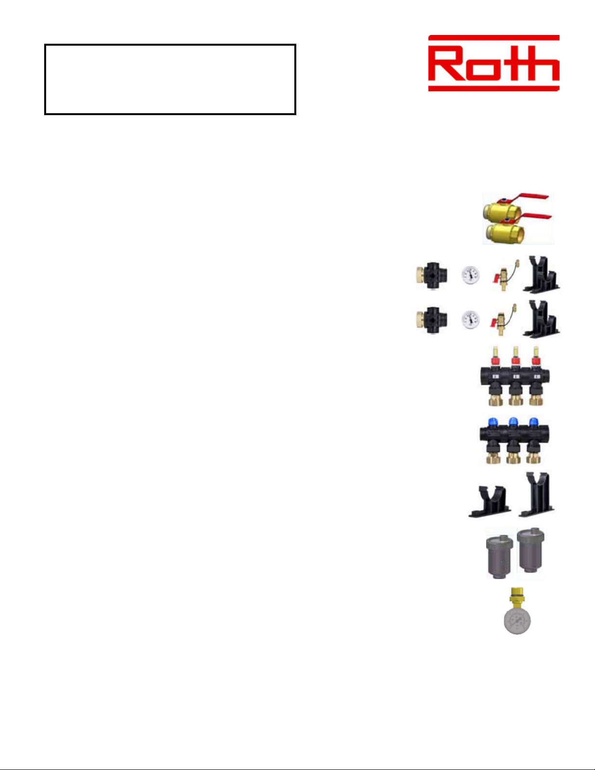
The pipe connections on the attached ball valves are 1 1/2” FPT. Use of a thread
sealant compatible with water service is recommended.
Loop Connections
Loop connections are standard threaded R-30 Euroconical compression tting
assemblies.
Care should be taken to ensure that the tubing ends are cut square, and that there is no debris
in the end of the tubing that may affect the integrity of the tting.
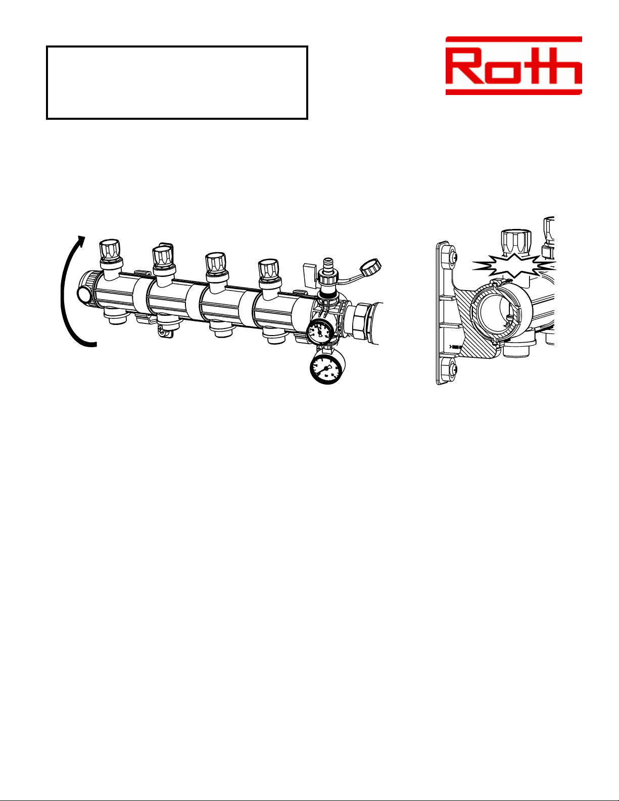
Loop tubing approach to the manifold should be carefully managed to allow for minimum bend
radius requirements and bend supports should be used if there are concerns for tubing kinking
during manifold and oor installation and nishing.
Caution: Alu-Laser Plus tubing must be reamed with Roth Alu-Laser Plus reaming tool. This
puts a bevel on the inside of the pipe and allows the tting to be inserted into the pipe without
disturbing the o-rings on the tting. Failure to do so will cause leaks.
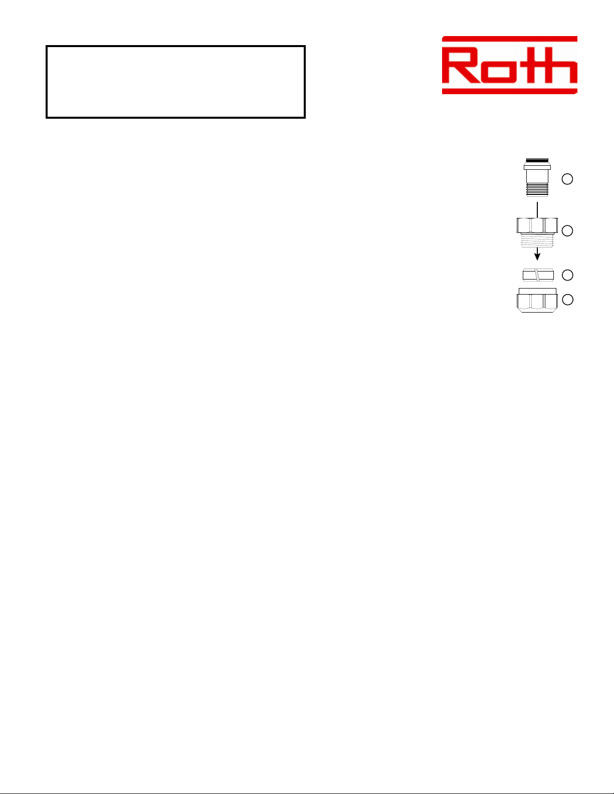
Attaching Tubing to Manifold
• Place compression nut onto tubing with thread opening facing tubing end
• Fit split ring over tubing and move away from end at least 2” (50mm)
• Insert tting into tubing until all barbs are covered
• Insert euroconical end of tting into manifold until o-ring is seated
• Push split ring up against tting
• Thread and tighten nut onto manifold
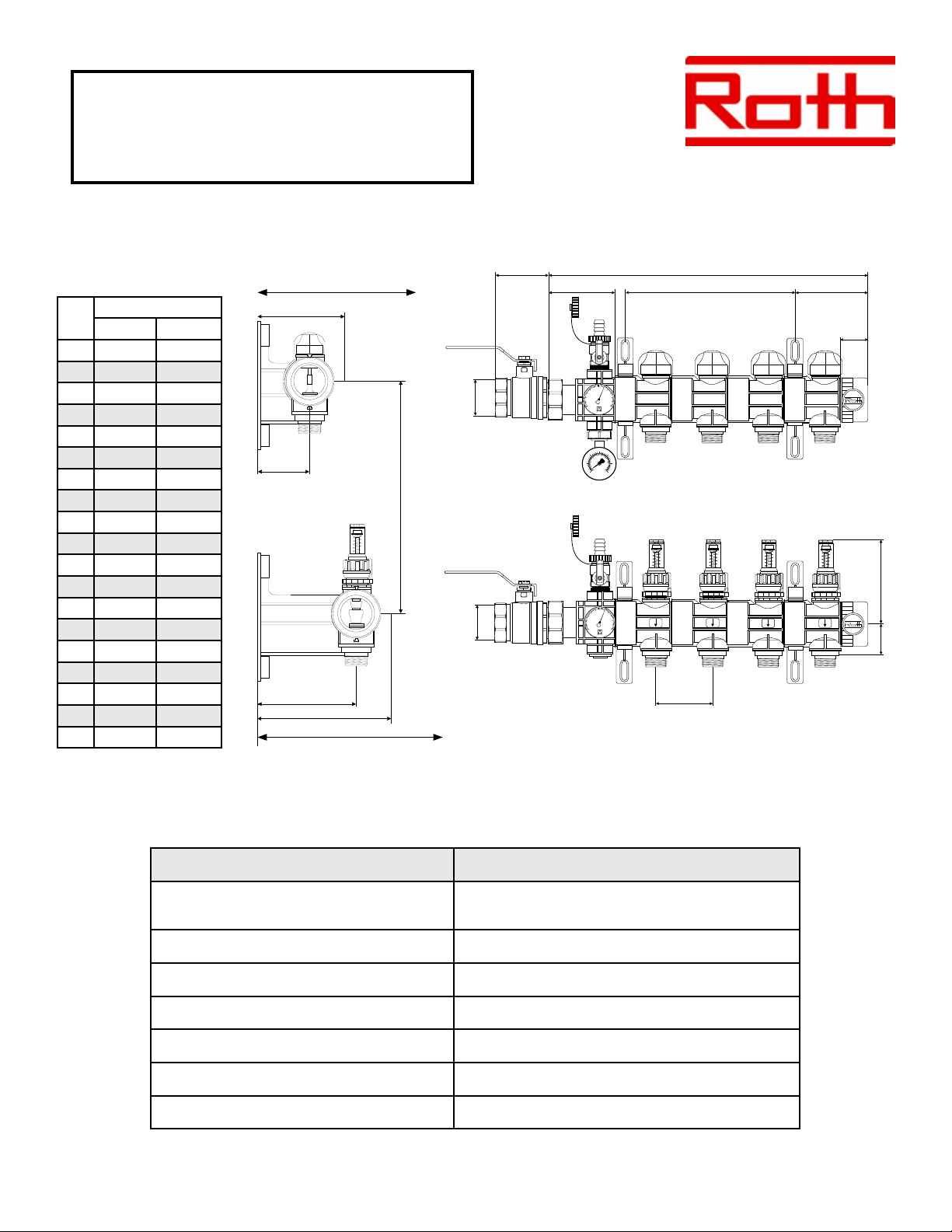
Roth Product # Description
PEX/PE-RT Fittings
2335001410 Manifold Tubing Fitting Assembly - 3/8” pkg of 10
2350003021 Manifold Tubing Fitting Assembly - 1/2” pkg of 10
2350003022 Manifold Tubing Fitting Assembly - 5/8” pkg of 10
2335001034 Manifold Tubing Fitting Assembly - 3/4” pkg of 2
Alu-Laser Plus Fittings
2347131300 Manifold Tubing Fitting Assembly - 3/8” pkg of 10
2347002331 Manifold Tubing Fitting Assembly - 1/2” pkg of 10
2347002332 Manifold Tubing Fitting Assembly - 5/8” pkg of 10

Roth CM Manifold System
Installation Instructions
Attaching 3/4” tubing to manifold
• Insert euroconical end of tting (1) into manifold until o-ring is seated
• Thread and tighten threaded adaptor (2) onto manifold
• Place compression nut (4) onto tubing
• Fit split ring (3) over tubing and move away from end at least 2” (50mm)
• Push tubing onto barbed tting as far as possible. Be sure all barbs are covered
• Push split ring to within 1/8” from end of tubing
• Thread and tighten nut onto adaptor
Filling and purging
The direction of ow for lling and purging should always be from the supply manifold, through the
loops, to the return manifold.
Filling
• Close supply and return isolation ball valves
• Close the air vents
• Attach service hoses to barbed ttings on supply and return manifold ll/drain valves and
secure with hose clamps. Open ll/drain valves
• Open all loop supply and return main valves
• Open water source and begin lling manifolds and loops. When a full stream of water exits
the return hose open the manual air vents until water seeps out and close
• Shut off the water source and close ll/drain valves
Purging
Note: Purging is most effective when each loop is purged individually. Domestic water pressure or
a jet pump may be necessary to purge trapped air from the system.
• Attach service hoses to barbed ttings on supply and return manifold ll/drain valves and
secure with hose clamps. Place return service hose in bucket to observe when air bubbles
no longer exit the system, indicating it is purged. Open ll/drain valves.
• Open the return valve of the rst heating loop (1)
• Open the supply valve of the rst heating loop (3)
• Close all remaining supply and return valves (2)
1
2
4
3

Roth CM Manifold System
Installation Instructions
• Purge rst loop with 40 - 70 psi to remove trapped air in loop
• Allow water to circulate until no air is discharged into the bucket
• Close supply and return valves on the rst loop
• Repeat procedure until all loops have been purged
• Open the air vents until water seeps out and close
• Shut off the water source, close ll/drain valves and remove service hoses
Pressure Testing
Air test
• Pressurize system to 87 psi (6 bar) for a minimum of 2 hours
• Pressure drop allowance after this test is a maximum of 3 psi (0.2 bar)
• If pressure drop is greater, use leak detection uid or ultrasonic leak detector to detemine
source of leak
Fluid test
• Pressurize system to 87 psi (6 bar) for a minimum of 24 hours
• If pressure drop occurs, check for leaks
• Use caution when pressure testing with water in colder climates where freezing could occur

Roth CM Manifold System
Installation Instructions
Loop ow adjustment
• The owmeter is shipped in the fully closed position
• To open the ow valve and set the loop ow rate pull the stop ring
(1) up and turn owmeter (2) counterclockwise
• Once the ow rate is set, turn stop ring clockwise until the stop
engages the stop on the owmeter
• Push the stop ring down to lock
1
2
1 2 3 4 5 6 7 8 9 10 11 12 13 14 15 16 17 18 19 20
0.00
5.00
10.00
15.00
20.00
25.00
30.00
35.00
40.00
45.00
50.00
55.00
60.00
65.00
14.5
13.05
11.6
10.15
8.7
7.25
5.8
4.35
2.9
1.45
Pressure Drop
psi
Number of Loops
Flow Rate
gpm
CM Manifold Pressure Drop Graph
Table of contents
Other Roth Control Unit manuals