38
2.1 Technical data SUPERTRONIC 3 SE
Art.-No. 05.6253 SUPERTRONIC 3 SE, 110 V
Art.-No. 05.6254 SUPERTRONIC 3 SE AUTO, 110 V
Art.-No. 05.6250 SUPERTRONIC 3 SE, 230 V
Art.-No. 05.6255 SUPERTRONIC 3 SE AUTO, 230 V
Cutting capacity: BSPT R ¼” … 3”, NPT ¼” … 3”, bolt thread 3/8” … 2”
Speed: 33 rpm under no load
Motor: Single-phase universal motor 1700 W, overload protection
Protection class: I
Frequency: 50/60 Hz
Weight: 74 kg (without accessories)
Dimensions: 650 x 480 x 420 mm (LxWxH)
Thread-tapping head: Standard tapping head ½” … 2” and 2” … 3”
Automatic tapping head ½” … 2” and 2 ½” … 3”
Thread jaws: ½” … ¾”, 1” … 2”, 2 ½” … 3”
2.1 Technical data SUPERTRONIC 4 SE
Art.-No. 05.6470 SUPERTRONIC 4 SE, 110 V
Art.-No. 05.6475 SUPERTRONIC 4 SE AUTO, 110 V
Art.-No. 05.6460 SUPERTRONIC 4 SE, 230 V
Art.-No. 05.6465 SUPERTRONIC 4 SE AUTO, 230 V
Cutting capacity: BSPT R ¼” … 4”, NPT ¼” … 4”, bolt thread 3/8” … 2”
Speed: 22/50 rpm under no load
Motor: Single-phase universal motor 1750 W, overload protection
Protection class: I
Frequency: 50/60 Hz
Weight: 105 kg (without accessories)
Dimensions: 750 x 540 x 480 mm (LxWxH)
Thread-tapping head: Standard tapping head ½” … 2”, 2” … 3”,3.12”…4”
Automatic tapping head ½” … 2” and 2 ½” … 4”
Thread jaws: ½” … ¾”, 1” … 2”, 2 ½” … 4”
3 Functions of the thread-tapping machine
3.1 Overview / accessories / description
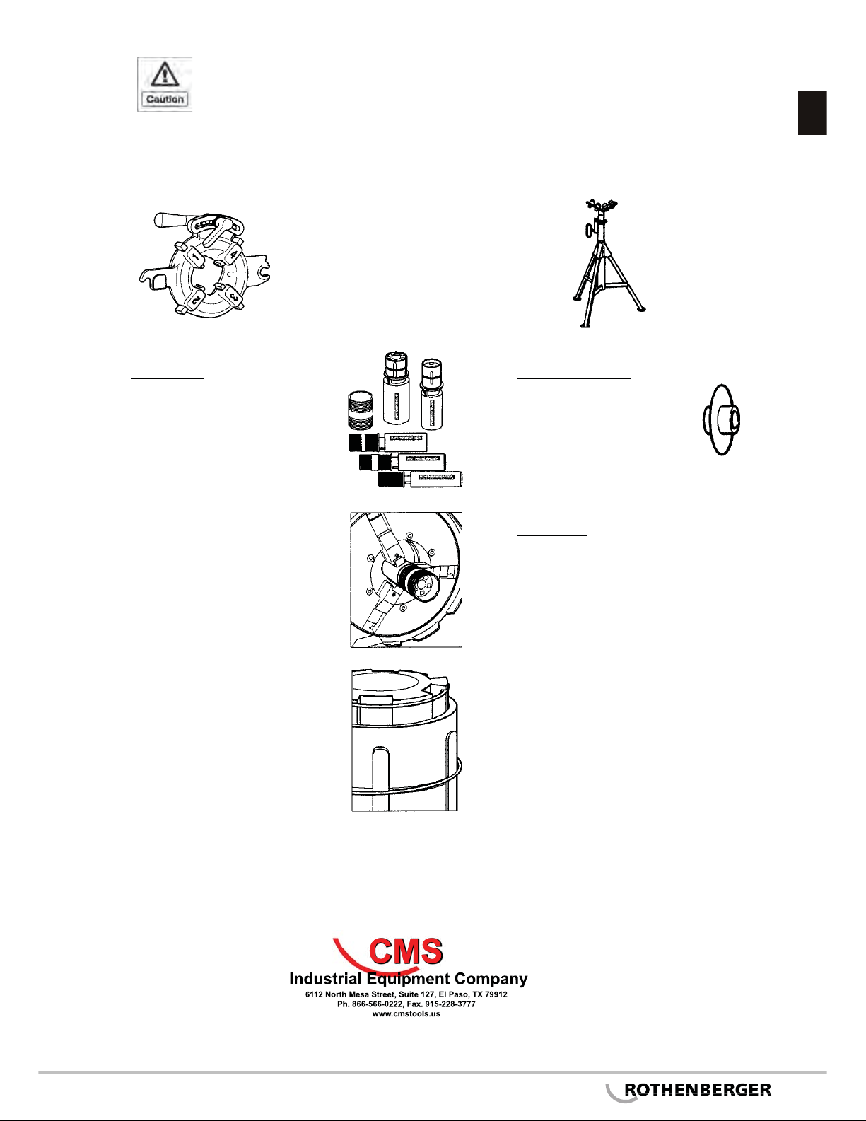
3.1.1 Overview, thread-tapping machine
Overview, control elements (> see front fold-out page):
1 Pipe cutter 7a Overload protection switch for machines with pedal
2 Thread-tapping jaws 7b On / Off switch for machines without pedal
3 Internal deburrer 8 Centring chuck
4 Tool carriage 9 Clamping chuck
5 Oil drainage screw 10 Thread-tapping head
6 Feeder hand wheel
3.1.2 Overview, automatic thread-tapping heads 2 SE and 3 SE
Overview, control elements (> see front fold-out page):
11 T-handle 16 Profile pin
12 Selector pin (silver) 17 Locking lever, body
13 Selector pin (black) 18 Locking lever, clamping head
14 Threaded pin (fast adjustment) 19 Cam plate
15 Profile body 20 Selector block