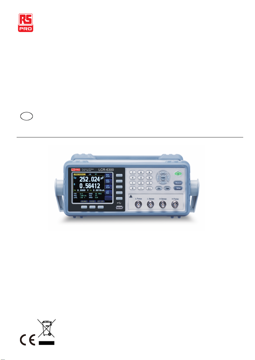
RS PRO LCR-6000 Series User manual

Instruction Manual
LCR-6000 Series
LCR Meter
EN FR DE IT SP

2

LCR-6000 Series Instruction Manual/English
13/12/2019 Version No. 002 3
Table of Contents
SAFETY INSTRUCTIONS................................................. 6
Safety Summary......................................................... 6
UNPACKING AND PREPERATION................................... 8
Incoming Inspection.................................................... 8
Environmental Requirements ..................................... 9
Cleaning ..................................................................... 9
How to Remove the Handle........................................ 9
OVERVIEW ..................................................................... 11
Introduction................................................................11
Main Specifications and Features..............................12
Test Signal.................................................................14
Main Functions..........................................................15
Measurement Assistance Functions..........................16
Options......................................................................17
STARTUP........................................................................ 19
Front panel ................................................................20
Rear Panel.................................................................21
Power On/Off.............................................................22
Warm‐up Time..........................................................22
Connect to the Device Under Test (DUT)..................23
MEASURE KEY............................................................... 24
[MEAS DISPLAY] Page.............................................24
[OPEN/SHORT] Page................................................35
[LIST SETUP] Page...................................................40

LCR-6000 Series Instruction Manual/English
4 13/12/2019 Version No. 002
[LIST MEAS] Page....................................................44
SETUP KEY..................................................................... 50
[MEAS SETUP] Page................................................51
[BIN SETUP] Page....................................................56
[BIN MEAS] Page......................................................64
[BIN COUNT] Page...................................................66
SYSTEM CONFIGURATIONS.........................................68
[SYSTEM CONFIG] Page.........................................69
[SYSTEM INFO] Page ..............................................77
FILE OPERATION........................................................... 78
[FILE] Page...............................................................79
HANDLER INTERFACE................................................... 82
Connection................................................................85
Timing Chart for Handler Interface............................87
EXAMPLES .....................................................................88
Basic Measurement Procedure.................................88
Example....................................................................90
REMOTE CONTROL.......................................................93
RS‐232 Interface ......................................................94
USB Interface............................................................95
Install BSU Driver......................................................96
COMMAND REFERENCE............................................... 99
Terminator.................................................................99
Notation Conventions and Definitions .......................99
Command Structure................................................100

LCR-6000 Series Instruction Manual/English
13/12/2019 Version No. 002 5
Header and Parameters ..........................................103
Command Reference ..............................................105
DISPlay Subsystem.................................................106
FUNCtion Subsystem..............................................108
FREQuency Subsystem ..........................................112
LEVel Subsystem ....................................................113
APERture Subsystem..............................................116
FETCh Subsystem ..................................................118
COMParator Subsystem..........................................122
LIST Subsystem......................................................127
CORRection Subsystem..........................................129
TRIGger Subsystem................................................132
BIAS Subsystem......................................................134
FILE Subsystem......................................................135
ERRor Subsystem...................................................137
SYSTEM Subsystem...............................................138
Common Commands...............................................140
SPECIFICATION........................................................... 141
General Specification ..............................................142
Dimensions..............................................................146
ACCURACY................................................................... 147
Accuracy..................................................................148
Correction factors that affect measurement
accuracy..................................................................151
Declaration of Conformity........................................155

LCR-6000 Series Instruction Manual/English
6 13/12/2019 Version No. 002
SAFETY INSTRUCTIONS
Safety Summary
WARNING
Warning: Identifies conditions or practices that could result in
injury or loss of life.
DANGEROUS
DANGER High Voltage
When you notice any of the unusual conditions listed below,
immediately terminate operation and disconnect the power cable.
Please contact the RS COMPONENTS service center
representative for repair of the instrument. If you continue to
operate without repairing the instrument, there is a potential fire
or shock hazard for operators.
The instrument is operating abnormally if:
The instrument emits abnormal noise, smell, smoke, or a
spark-like light during the operation.
The instrument generates high temperature or electrical
shock during operation.
The power cable, plug, or receptacle on the instrument is
damaged.
Foreign substances or liquid has fallen into the instrument.
The following general safety precautions must be observed
during all phases of operation, service, and repair of this
instrument. Failure to comply with these precautions or with
specific WARNINGS elsewhere in this manual may impair the
protection provided by the equipment. In addition it violates safety
standards of design, manufacture, and intended use of the
instrument.

LCR-6000 Series Instruction Manual/English
13/12/2019 Version No. 002 7
Disclaimer
RS COMPONENTS assumes no liability for the customer's failure
to comply with these requirements.
Ground the
Instrument
To avoid electric shock hazards, the instrument chassis and
cabinet must be connected to a safety earth ground by the
supplied power cable with earth blade.
DO NOT
Operate in an
Explosive
Atmosphere
Do not operate the instrument in the presence of inflammable
gasses or fumes. Operation of any electrical instrument in such
an environment constitutes a definite safety hazard.
Keep Away from
Live Circuits
Operating personnel must not remove instrument covers.
Component replacement and internal adjustments must be made
by qualified maintenance personnel. Do not replace components
with the power cable connected. Under certain conditions,
dangerous voltages may exist even with the power cable is
removed. To avoid injuries, always disconnect the power and
discharge the circuits before touching them.
DO NOT Service
or Adjust Alone
Do not attempt internal service or adjustment unless another
person, capable of rendering first aid and resuscitation, is
present.
DO NOT
Substitute Parts
or Modify
Instrument
Because of the danger of introducing additional hazards, do not
install substitute parts or perform unauthorized modifications to
the instrument. Return the instrument to a RS COMPONENTS
authorized service center for service and repair to ensure that
safety features are maintained.

LCR-6000 Series Instruction Manual/English
8 13/12/2019 Version No. 002
UNPACKING AND
PREPERATION
This chapter describes how to set up and start the LCR-6000
Series LCR Meter.
Incoming Inspection
Environmental Requirements
Cleaning
How to Remove the Handle
Incoming Inspection
After you receive the instrument, perform the following checks
during unpacking according to the following procedure:
WARNING
If the external face of the instrument (such as the cover, front/rear
panel, VFD screen, power switch, and port connectors) appears
to have been damaged during transport, do not turn on the power
switch. Otherwise, you may get an electrical shock.
Make sure that the packing box or shock-absorbing material
used to package the instrument has not been damaged.
Refer to the <Packing List> in the packing box, check that all
packaged items supplied with the meter have been provided as
per the specified optioned.
Note
If an abnormality is detected, contact the company and transport
the meter to your nearest RS COMPONENTS Instruments sales
or service office. Save the packing box, shock-absorbing
material, and packaged items as you received them in case you
need to mail the instrument to an authorized RS Components
distributor or service center.

LCR-6000 Series Instruction Manual/English
13/12/2019 Version No. 002 9
Environmental Requirements
Set up the LCR-6000 Series where the following environmental
requirements are satisfied.
Operating Environment
Ensure that the operating environment meets the following
requirements:
Temperature:
0ºC to 50ºC
Temperature range at
calibration:
23ºC±5ºC (<1ºC deviation from the
temperature when performing calibration)
Humidity:
<70% at wet bulb temperature ≤40ºC
(non-condensation)
Altitude:
0 to 2000m
Cleaning
To prevent electrical shock, disconnect the LCR-6000 Series
power cable from the receptacle before cleaning. Use a dry cloth
or a cloth slightly dipped in water to clean the casing. Do not
attempt to clean the LCR-6000 Series internally.
WARNING
Don’t Use Organic Solvents (such as alcohol or gasoline) to
clean the Instrument.
How to Remove the Handle
Ahandle kit is attached to theLCR-6000 Series:
Figure 1-1
How to remove
the handle
➜
1 Retracted
2 Extended

LCR-6000 Series Instruction Manual/English
10 13/12/2019 Version No. 002
3 Carrying Position
Remove Handle
(Lift the handle perpendicular to the unit while pulling it in the direction of 1.)

LCR-6000 Series Instruction Manual/English
13/12/2019 Version No. 002 11
OVERVIEW
This chapter contains general information about LCR-6000
Series .The information is organized as follows.
Introduction
Main Specifications
Feature overview
Introduction
Thank you for purchasing an LCR-6000 Series LCR meter.
The RS COMPONENTS LCR-6000 Series is a general-purpose
LCR meter for incoming inspection of components, quality
control, and laboratory use.
The LCR-6000 Series is used for evaluating LCR components,
materials, and semiconductor devices over a wide range of
frequencies (10 Hz to 300 kHz) and test signal levels (10.00mV
to 2.00V & 100.0uA to 20.00mA).
With its built-in comparator, the LCR-6000 Series can output
comparison/decision results for sorting components into a
maximum of ten bins. Furthermore, by using the handler
interface, the LCR-6000 Series can be easily combined with a
component handler, and a system controller to fully automate
component testing, sorting, and quality-control data processing.
The list meas function permits entry of up to 10 frequencies or
test signal levels points to be automatically measured.

LCR-6000 Series Instruction Manual/English
12 13/12/2019 Version No. 002
Main Specifications and Features
Test Function
Cs-Rs, Cs-D, Cp-Rp, Cp-D, Lp-Rp, Lp-Q, Ls-Rs, Ls-Q,
Rs-Q, Rp-Q, R-X, DCR, Z-θr, Z-θd, Z-D, Z-Q
Equivalent Circuit
Serial and Parallel
Table 2-1
Equivalent
Circuit
Circuit
Dissipation Factor
Conversion
L
Lp
Rp
D=2π
FLp/Rp=1/Q
Ls=Lp/(1+D2)
Rs=RpD2/(1+D2)
Ls
Rs
D=Rs/2π
FLs=1/Q
Lp=(1+D2)Ls
Rp=(1+D2)Rs/D2
C
Cp
Rp
D=1/2π
FCpRp=1/Q
Cs=(1+D2)Cp
Rs=RpD2/(1+D2)
Cs Rs
D=2π
FCsRs=1/Q
Cp=Cs/(1+D2)
Rp=Rs(1+D2)/D2
Q=Xs/Rs, D=Rs/Xs, Xs=1/2πFCs=2πFLs
Ranging
Auto, Hold and Nominal range. Total 9 Ranges.
About Nominal ranges: The LCR-6000 Series will automatically
select the best range according to the nominal value

LCR-6000 Series Instruction Manual/English
13/12/2019 Version No. 002 13
Measurement Speed
Fast:40 readings per second; 25ms/per reading*1
Medium:10 readings per second; 100ms/per reading*1
Slow: 3 readings per second; 333ms/per reading*1
You can also specify the averaging factor within the range of 1 to
256 in steps of 1 to improve performance.
Note
*1. Measurement speed in 300kHz, typical.
Trigger Mode
Includes Internal, Manual, External and Bus Trigger.
Basic Accuracy
0.05%@SLOW/MED
0.1%@FAST
Display Range
Table 2-2
Display Range
Parameter
Display Range
L
0.00001uH ~ 9999.99H
C
0.00001pF ~ 9999.99mF
R, X, |Z|
0.00001Ω ~ 99.9999MΩ
G, B, |Y|
0.01nS ~ 999.999S
D
0.00001 ~ 9.99999
Q
0.00001 ~ 99999.9
θd
-179.999°~ 179.999°
θr
-3.14159 ~ 3.14159
DCR
0.00001Ω ~ 99.9999MΩ
Δ%
-999999% ~ 999999%

LCR-6000 Series Instruction Manual/English
14 13/12/2019 Version No. 002
Test Signal
Test Signal Frequency
LCR-6300: 10Hz~300kHz
LCR-6200: 10Hz~200kHz
LCR-6100: 10Hz~100kHz
LCR-6020: 10Hz~20kHz
LCR-6002: 10Hz~2kHz
Frequency Accuracy: ±0.01%
Test Signal Level
AC:
10.00mV- 2.00V (±10%)
CV mode:10.00mV- 2.00V(±6%)
100.0uA- 20.00mA (±10%)
CC mode:100.0uA- 20.00mA(±6%) @2VMax
DCR:
+2V, 0.066A(Max.), Output impedance fixed 30Ω
Output impedance
30Ω, 50Ωand 100Ω

LCR-6000 Series Instruction Manual/English
13/12/2019 Version No. 002 15
Main Functions
Correction Function
OPEN/SHORT correction:
Eliminates measurement errors due to stray parasitic impedance
in the test fixtures.
Comparator Function (Sorting)
Bin sort
The primary parameter can be sorted into BIN1-BIN9, AUX, OUT
and HI/IN/LO for each of the primary measurement parameters.
The sequential mode or tolerance mode can be selected as the
sorting mode.
Limit Setup
Absolute value, deviation value, and % deviation value can be
used for setup.
BIN count
Countable from 0 to 999999
List Sweep
Points
There is a maximum of 10 points.
Sweep parameters
Test frequency, test voltage, test current.
Comparator function of list sweep
The comparator function enables you to set one pair of lower and
upper limits for each measurement point.
You can select from:
Judge with the first sweep parameter/Judge with the second
parameter/Not used for each pair of limits..

LCR-6000 Series Instruction Manual/English
16 13/12/2019 Version No. 002
Measurement Assistance Functions
Files
Up to 10 setup conditions can be written to/read from the built-in
non-volatile memory.
Key Lock
The front panel keys can be locked.
RS‐232/USB
Complies with SCPI.

LCR-6000 Series Instruction Manual/English
13/12/2019 Version No. 002 17
Options
USB host port
Universal serial bus jack, type-A (4 contact positions, contact 1 is
on your left); female; for connection to USB memory devices
only.
USB disk type: Flash disk only.
Format: FAT / FAT32 / exFAT.
Max memory size: 128GB.
Save Screen
After a USB disk has been inserted into the USB host port of the
LCR meter and if the meter detects that the USB disk is usable,
the meter will show “USB Disk Ready. Press <Enter> to save
screen.” on the lower part of the LCD screen.
Figure 2-1
Disk Ready
If the keypad is not needed to enter a numeric value, a
screenshot of the meter’s LCD display can be captured and
saved to the USB disk by depressing the Enter key. If the screen
shot is saved successfully, “Screen saved.” will be shown in the
message area at the bottom of the screen. The location and
name of the screenshot will also be shown, for example: F:\LCR-
6300\Screen\ScreenShot001.bmp.

LCR-6000 Series Instruction Manual/English
18 13/12/2019 Version No. 002
Figure 2-2
Screen Saved
DC Bias Voltage
0V ~ ±2.5V
Accuracy: ±0.5%+0.005V

LCR-6000 Series Instruction Manual/English
13/12/2019 Version No. 002 19
STARTUP
This chapter describes names and functions of the front panel,
rear panel, and screen display and provides the basic procedures
for operating the LCR-6000 Series.
Front panel summary
Rear panel summary
Power On/Off
Connect to Device under test

LCR-6000 Series Instruction Manual/English
20 13/12/2019 Version No. 002
Front panel
1
11
5
3
12
6
7
8
4
10 9
2
No.
Description
No.
Description
1
LCD Display
7
Setup Key
2
Soft-key
8
BNC Terminal
3
Number Key
9
Trigger Key
4
Cursor Key
10
ESC Key
5
Power Switch
11
USB Disk Port (USB-Host)
6
Measure key
12
System Soft-key
This manual suits for next models
5
Table of contents
Other RS PRO Measuring Instrument manuals

RS PRO
RS PRO ISM 400 User manual

RS PRO
RS PRO RS-136 User manual

RS PRO
RS PRO RS-960 User manual

RS PRO
RS PRO RS-5200 User manual

RS PRO
RS PRO 623-883 Manual

RS PRO
RS PRO RSSA3000X User manual

RS PRO
RS PRO ICM A6N User manual

RS PRO
RS PRO 877-1791 User manual

RS PRO
RS PRO DT-388 User manual

RS PRO
RS PRO RS-1013 User manual

RS PRO
RS PRO RS-1360A User manual

RS PRO
RS PRO ISM 410 User manual

RS PRO
RS PRO RS 1107-UT User manual

RS PRO
RS PRO RS-8880 User manual

RS PRO
RS PRO 123-8769 User manual

RS PRO
RS PRO RS-1150 User manual

RS PRO
RS PRO RS-5322 User manual

RS PRO
RS PRO RS-90 User manual

RS PRO
RS PRO IPM 3600N User manual

RS PRO
RS PRO RS-8920 User manual