13/08/2017 Version No. 001
MeterScope/English MeterScope/English
13/08/2017 Version No. 001 54
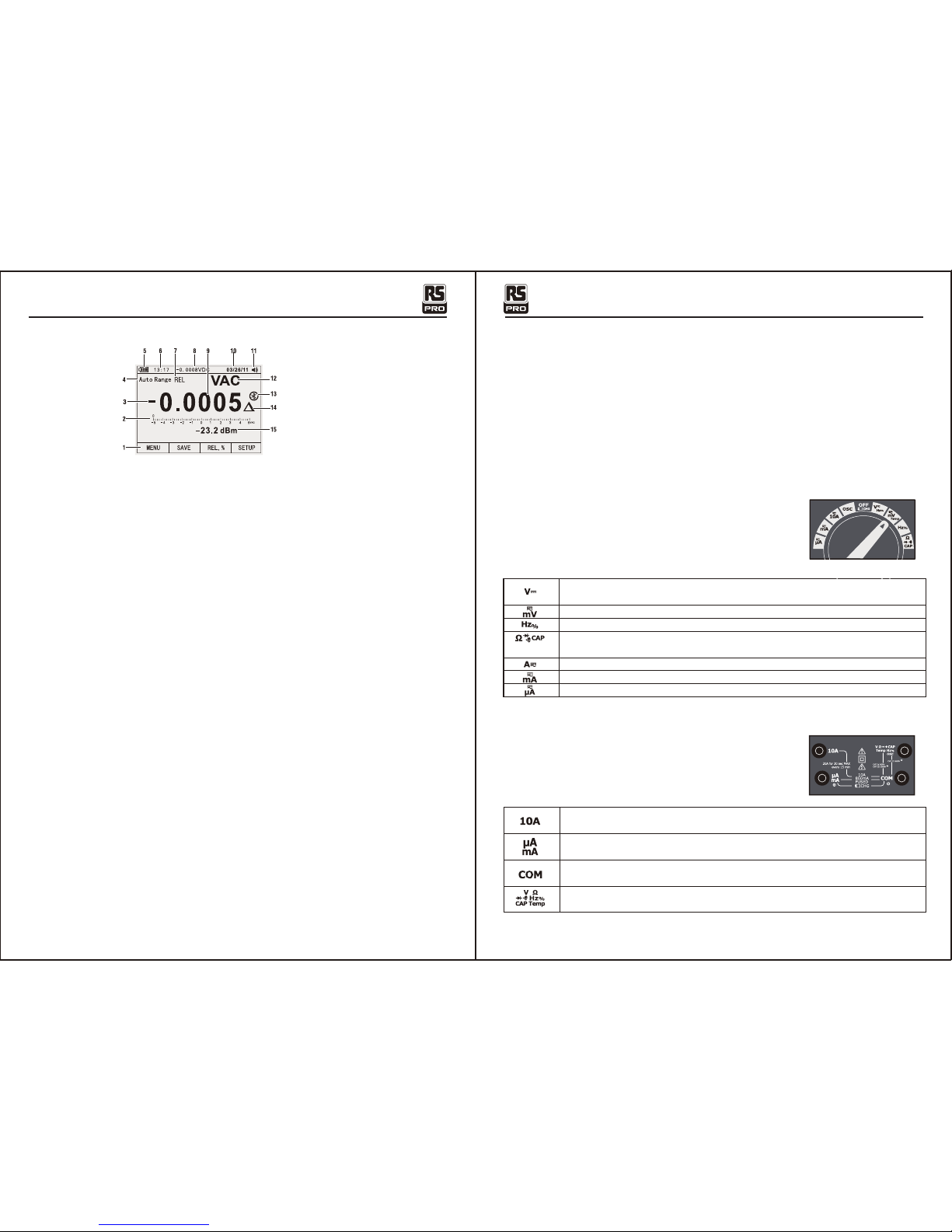
1.Soft key labels Indicates the function of the button just below the displayed label.
2.Bar graph Analog display of the input signal(See the "Bar Graph" section for more information).
3.Minus sign Indicates a negative reading.
4.Indicates the range the Meter is in and the ranging mode (auto or manual)
5.Battery level Indicates the charge level batteries.
6.Time Indicates the time set in the internal clock.
7.Mode annunciators Indicates the Meter's mode.
8.Minimeasurement Displays the lightning bolt (when necessary) and the input value when the
primary and secondary displays are covered by a menu or pop-up message.
9.Main display Displays measurement information about the input signal.
10.Date Indicates the date set in the internal clock.
11.Beeper Indicates the Meter’s beeper is enabled (not associated with the continuity beeper).
12.Units Indicates the units of measurement. Auxiliary Units Indicates unit less measurements
like Crest Factor.
13.Blue tooth Indicates activity over the communication link.
14.Relative Indicates the displayed value is relative to a reference value.
15.Secondary display Displays secondary measurement information about the input signal.
4-2.Understanding the Display 4-4.Page Area
The page area of the display is where the main meter content is displayed.
The primary display (upper half of the page area) is where the most important value of the selected
function is shown. The secondary display contains the bar graph and values that may be measured
in addition to the primary function value. For example, with frequency measurement selected in Vac,
the frequency value will appear in the primary display with the ac voltage value in the secondary
display.
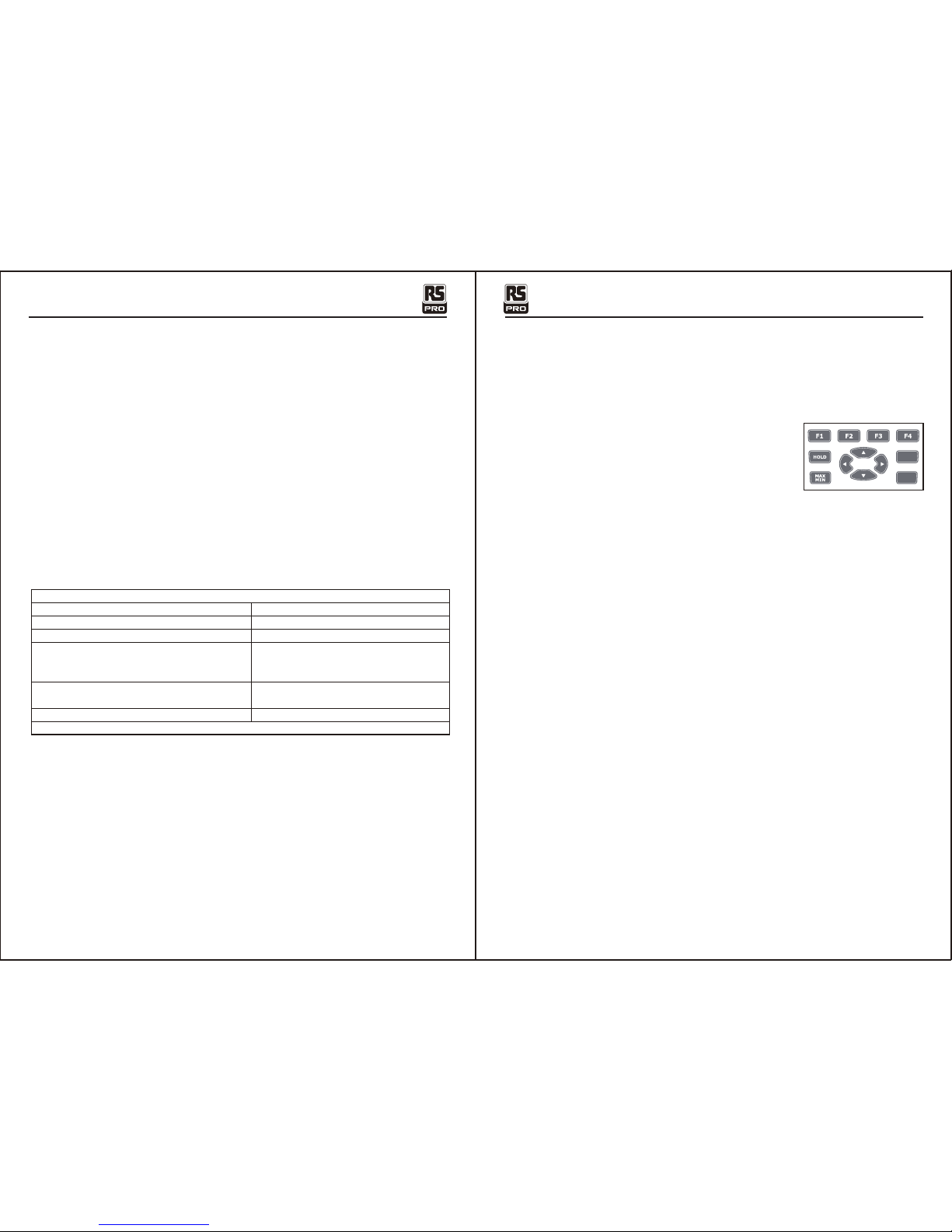
4-5.Softkey Labels
Labels for the four function softkeys (F1 through F4) appear in the bottom row of the display.
These labels will change based on the function and/or menu selection.
4-6.Understanding the Rotary Switch
Select a primary measurement function by positioning the rotary
switch to one of the icons around its perimeter. For each function,
the Meter presents a standard display for that function (range,
measurement units, and modifiers). Button choices made in one
function do not carry over into another function.
4-7.Using the Input Terminals
All functions except current use the VOHMSand COM input
terminals. The two current input terminals (A and mA/μA) are
Used as follows:
Current from 0 to 500 mA, use the uAmA and COM terminals.
Current between 0 and 10 A use the A and COM terminals.
Input for 0 A to 10.00 A current (20VA overload for 30 seconds
on, 10 minutes off),
Input for 0 A to 500 mA current measurements.
Return terminal for all measurements.
Input for voltage, continuity, resistance, diode test, conductance,
capacitance.
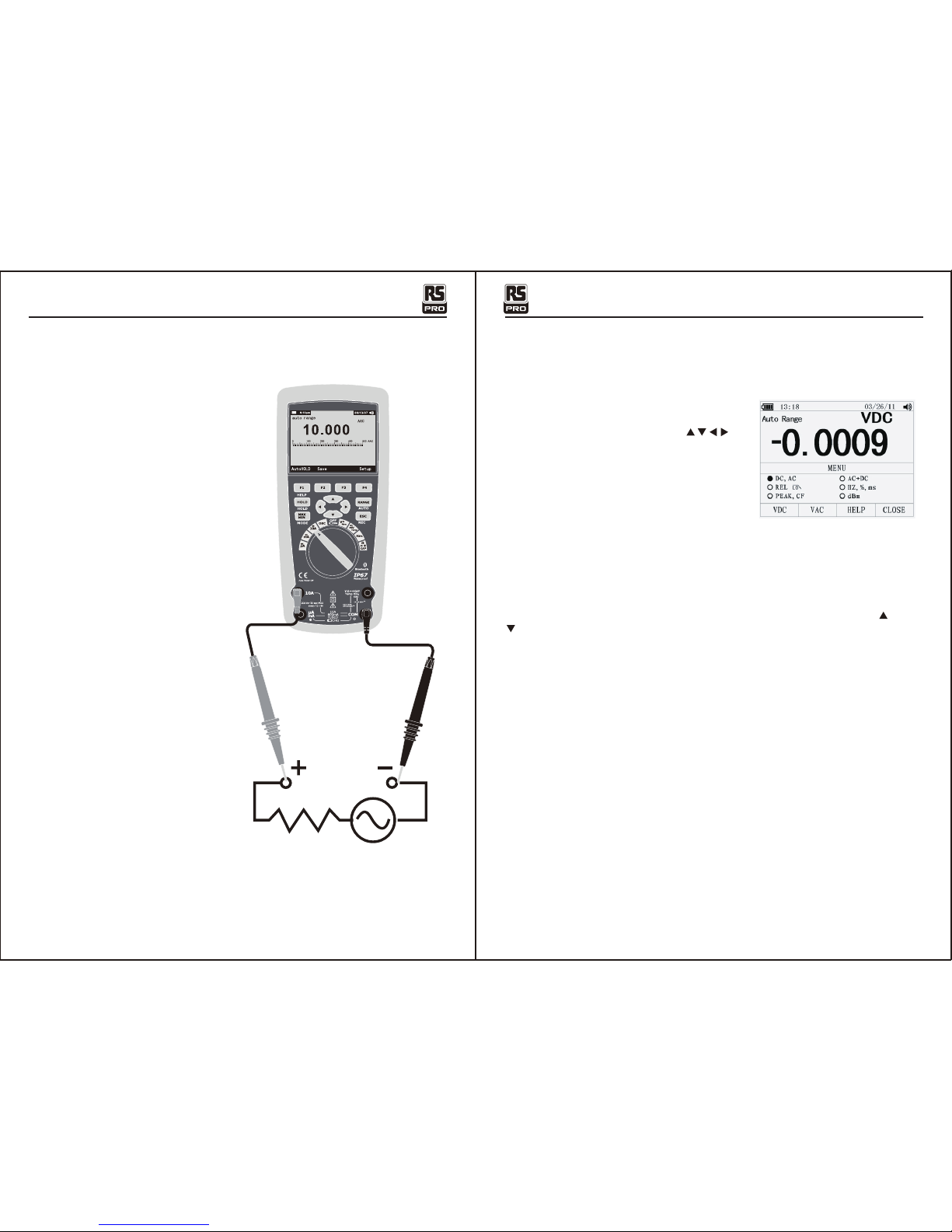
DC(AC) and AC+DC voltage measurements
AC voltage measurements
DC(AC) millivolts, ac+dc millivolt measurements
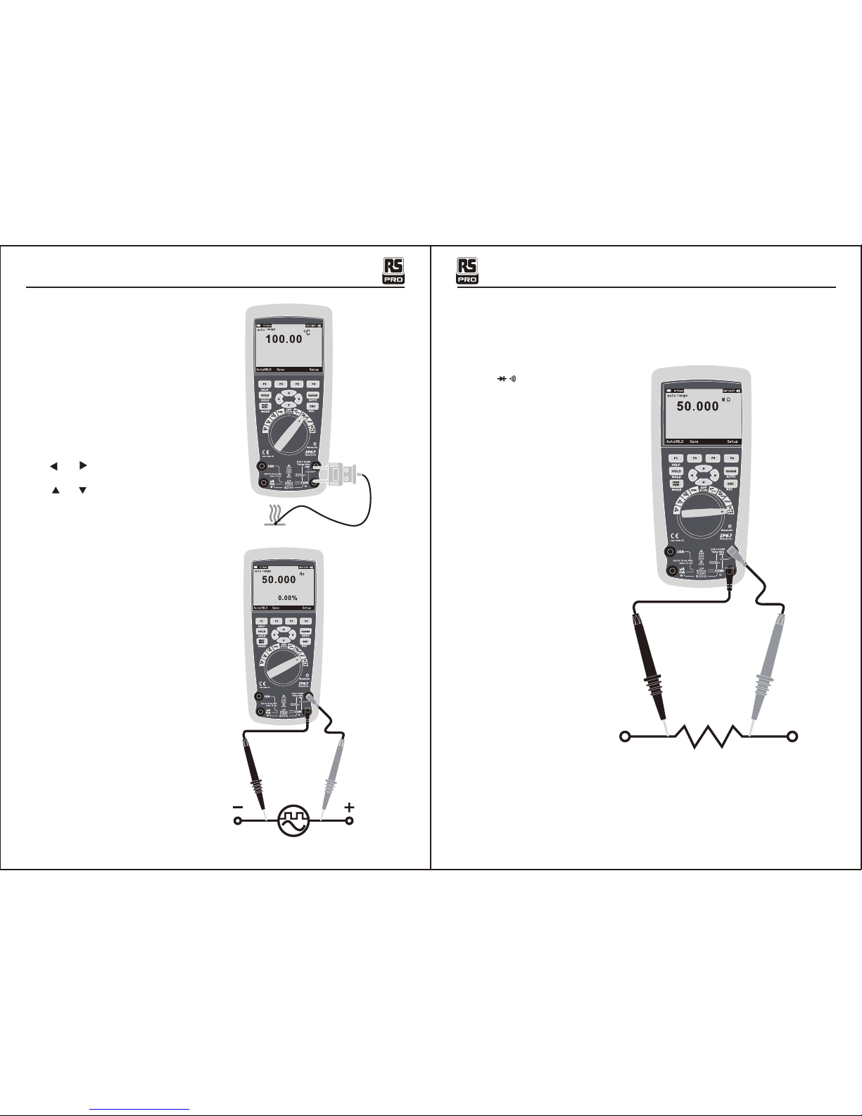
Frequency measurements
Resistance, Diode test, Capacitance and Continuity measurements
Temperature measurements
AC, DC and AC+DC amps measurements
AC, DC and AC+DC milliamps measurements
AC, DC and AC+DC microampere measurements up to 5,000μA