manuals.online logo
Brands
  1. Home
  2. •
  3. Brands
  4. •
  5. Rubbermaid
  6. •
  7. Indoor Furnishing
  8. •
  9. Rubbermaid FastTrack 5M13 User manual

Rubbermaid FastTrack 5M13 User manual

Pieces Qty Pieces Qty
Right/Left Vertical Panel
(3814713) 2Upright Bracket (L/R)
(NP5M2000) 2
Top/Bottom Panel
(3814705) 2Euro Screws, 6mm x 10mm
(1602392) 12
Backer Board
(2901884) 1Plastic Screw Covers
(1812256) 4
Left Door
(3814739) 1Handles with Screws,
#8 x 1-1/4", Phillips
(NP5M2100)
2
Right Door
(3814721) 1 4
Hinge Plates
(1608770)
Hinges
(NP5M2200)
4Door Pads
(1811399) 4
4
Confirmat Screws,
5mm x 40mm
(1602376)
8
Adjustable Shelf
(3814698) 1Nails
(1608217) 22
Shelf Support Pins
(FG3F80H1CHROM) 4
Hinge Plate Screws,
#6 x 5/8"
(1602160)
8
Metal Plates
(NP5M2400) 4
Pan Head Screws,
#8 x 1/2", Phillips
(1604281)
4
Metal Plate Fasteners
with Screws
(NP5M2500)
12 Feet with Screws,
#8 x 5/8", Phillips, Flat Head
(NP5M2300)
4
12
5M13 – Two Door Base
Cabinet Assembly Steps 1/8"
STEP 14
Ensure cabinet is square prior to adjusting hinges.
Rubbermaid Incorporated,
Huntersville, NC USA 28078-1801
U.S.A. 1-888-895-2110
Canada 1-866-595-0525
www.rubbermaid.com
L8-5M13-PO
© 2008 Rubbermaid Incorporated, Huntersville, NC U.S.A. 28078-1801 www.rubbermaid.com
Horizontal
HORIZONTAL ADJUSTMENT
Adjusts gap size
between doors.
VERTICAL ADJUSTMENT
For doors not flush
at top or bottom.
Vertical
Vertical
Horizontal
HORIZONTAL ADJUSTMENT
Adjusts gap size
between doors.
VERTICAL ADJUSTMENT
For doors not flush
at top or bottom.
Vertical
Vertical
Load Capacity
50
50
50
Upright Mounting
150 lbs. total
50
50
Floor Mounting
150 lbs. total
50
Base top of cabinet Base top of cabinet
5M17 WorkTop Installation
Intended for use with two FastTrack®base cabinets
• Align worktop over two base cabinets.
• Screw (4) #8 - 1" wood screws into the holes.
(NOT INCLUDED)
1
2
• Remove shelves from inside of cabinets.
• Use 1/8" drill bit. Drill through cabinet tops
four times equally spaced.
Refer to Figure 1
Figure 1
Place cabinet in desired location
against wall. Level cabinet using
adjustable feet.
Raise Front (turn right)
Raise Side (turn right)
Floor Mounting Adjusting Feet
STEP 13
STEP 1
Top
Bottom
Parts Required
• LeftVerticalPanel(1)
• RightVerticalPanel(1)
• HingePlates(4)
• EuroScrews(8)
Rail mounting requires a minimum height of 39.25" for base cabinets. Center to center
measurementbetweenrailsis30-3/16".Attachrailtowallperinstructionsprovided
with rail. (Dimensions to top of rail)
Measurements STEP 6
39.25"
30-3/16"
Floor
STEP 2
Parts Required
• TopPanel(1)
• ConrmatScrews(4)
• ScrewCovers(4) Top
Finished edge
down all sides
Tophookshouldbeinsertedinthe2ndopennotch
from the gripper on the inside row of notches.
Upright Mounting Instructions
HAZARD: Use two or more people to install cabinet.
Failure to do so can result in back or other injury.
HAZARD: If upright is not attached to stud,
the load claim is null and void.
Use the upright brackets
for upright mounting only.
Parts Required
• UprightBrackets(2)
• PanHeadScrews(8)
• EuroScrews(4)
Bottom
Top
Finished edge
down all sides
Parts Required
• Foot(4)
• FootScrews(12)
• BottomPanel(1)
• ConrmatScrews(4)
STEP 3A STEP 3B
Parts Required
• BottomPanel(1)
• ConrmatScrews(4)
Bottom
Finished edge
down all sides
STEP 4
Top
STEP 5
Parts Required
• BackerBoard(1)
• Nails(22)
Remove perforation
when upright
mounted only.
Bottom
Top
Finished edge
down all sides
Floor Mount Instructions
Choose Your Installation Method, Upright Mount or Floor Mount
Upright Mount Instructions
Sides of foot should
be square in corner.
Top
Bottom
Finished edge
down all sides
Insertconrmatscrew
through foot.
STEP 11
Parts Required
• Handles(2)
• HandleScrews(4)
STEP 10
Bottom
Top
Parts Required
• Doors(2)
• MetalPlates(4)
• MetalPlate
Fasteners
 withScrews(12)
STEP 9
Parts Required
• Hinges(4)
Center hinge
plate screw in
hinge slot.
Install hinges to
hinge plates.
Repeat for
other side.
STEP 12
Parts Required
• HingePlateScrews(8)
• DoorPads(4)
Assembledoorstothecabinet.
Shelf and Door Assembly Instructions
Finished
edge
Important:
STEP 7
Parts Required
• ShelfSupportPins(4)
STEP 8
Parts Required
• AdjustableShelf(1)
Bottom
Place the
adjustable shelves
on the pins.
Place pins at
desired locations
for adjustable shelves.
Adheredoorpads
to top and bottom
corners of doors.
One upright must be
attached to stud.
If two cabinets share an upright
it must be attached to stud.
Pieces Qty Pieces Qty
Right/Left Vertical Panel
(3814713) 2Upright Bracket (L/R)
(NP5M2000) 2
Top/Bottom Panel
(3814705) 2Euro Screws, 6mm x 10mm
(1602392) 12
Backer Board
(2901884) 1Plastic Screw Covers
(1812256) 4
Left Door
(3814739) 1Handles with Screws,
#8 x 1-1/4", Phillips
(NP5M2100)
2
Right Door
(3814721) 1 4
Hinge Plates
(1608770)
Hinges
(NP5M2200)
4Door Pads
(1811399) 4
4
Confirmat Screws,
5mm x 40mm
(1602376)
8
Adjustable Shelf
(3814698) 1Nails
(1608217) 22
Shelf Support Pins
(FG3F80H1CHROM) 4
Hinge Plate Screws,
#6 x 5/8"
(1602160)
8
Metal Plates
(NP5M2400) 4
Pan Head Screws,
#8 x 1/2", Phillips
(1604281)
4
Metal Plate Fasteners
with Screws
(NP5M2500)
12 Feet with Screws,
#8 x 5/8", Phillips, Flat Head
(NP5M2300)
4
12
5M13 – Two Door Base
Cabinet Assembly Steps 1/8"
STEP 14
Ensure cabinet is square prior to adjusting hinges.
Rubbermaid Incorporated,
Huntersville, NC USA 28078-1801
U.S.A. 1-888-895-2110
Canada 1-866-595-0525
www.rubbermaid.com
L8-5M13-PO
© 2008 Rubbermaid Incorporated, Huntersville, NC U.S.A. 28078-1801 www.rubbermaid.com
Horizontal
HORIZONTAL ADJUSTMENT
Adjusts gap size
between doors.
VERTICAL ADJUSTMENT
For doors not flush
at top or bottom.
Vertical
Vertical
Horizontal
HORIZONTAL ADJUSTMENT
Adjusts gap size
between doors.
VERTICAL ADJUSTMENT
For doors not flush
at top or bottom.
Vertical
Vertical
Load Capacity
50
50
50
Upright Mounting
150 lbs. total
50
50
Floor Mounting
150 lbs. total
50
Base top of cabinet Base top of cabinet
5M17 WorkTop Installation
Intended for use with two FastTrack®base cabinets
• Align worktop over two base cabinets.
• Screw (4) #8 - 1" wood screws into the holes.
(NOT INCLUDED)
1
2
• Remove shelves from inside of cabinets.
• Use 1/8" drill bit. Drill through cabinet tops
four times equally spaced.
Refer to Figure 1
Figure 1
Place cabinet in desired location
against wall. Level cabinet using
adjustable feet.
Raise Front (turn right)
Raise Side (turn right)
Floor Mounting Adjusting Feet
STEP 13

Other Rubbermaid Indoor Furnishing manuals
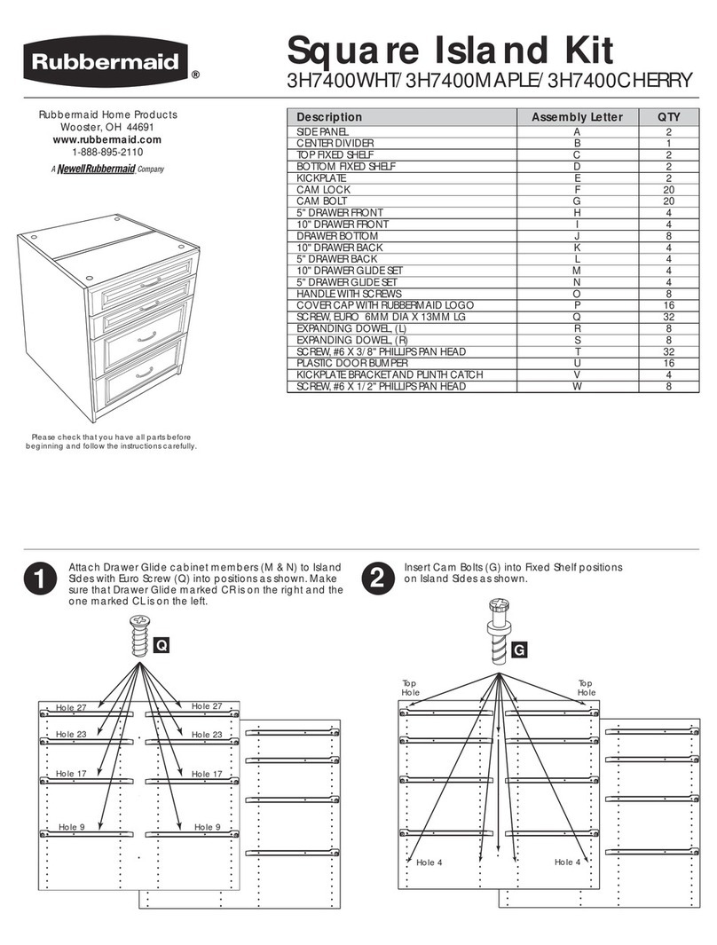
Rubbermaid FASTTRACK 7W96 User manual

Rubbermaid

Rubbermaid FASTTRACK 7W96 User manual

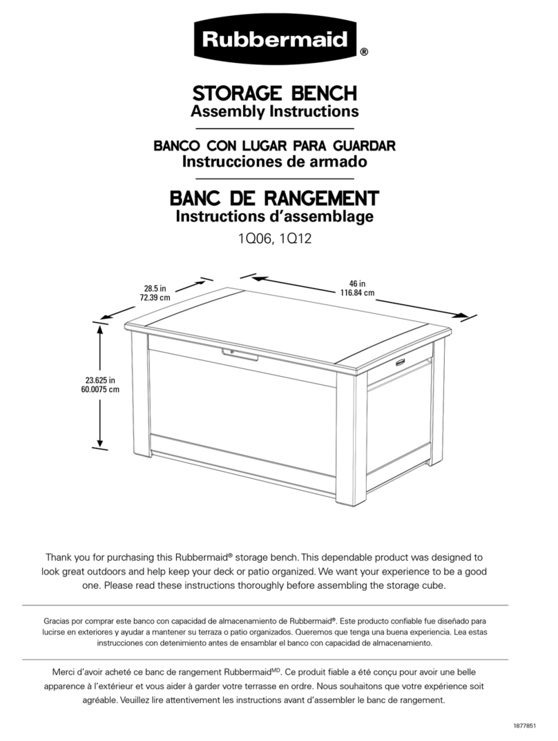
Rubbermaid Square Island Kit User manual

Rubbermaid

Rubbermaid Square Island Kit User manual

Rubbermaid LARGE VERTICAL STORAGE SHED User manual

Rubbermaid

Rubbermaid LARGE VERTICAL STORAGE SHED User manual

Rubbermaid 1M89 User manual

Rubbermaid

Rubbermaid 1M89 User manual

Rubbermaid 7Y93 User manual

Rubbermaid

Rubbermaid 7Y93 User manual

Rubbermaid Homefree Series User manual

Rubbermaid

Rubbermaid Homefree Series User manual

Rubbermaid homefree Series User manual

Rubbermaid

Rubbermaid homefree Series User manual

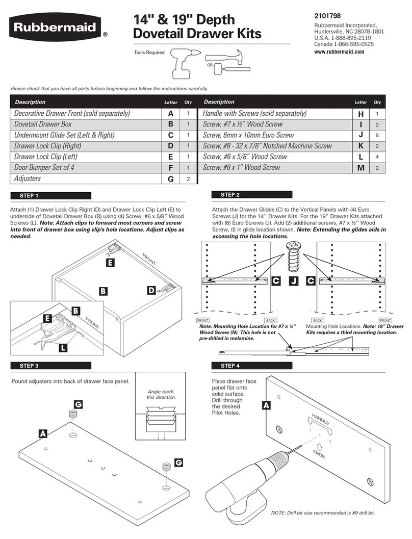
Rubbermaid Dovetail Drawer Series User manual
Rubbermaid

Rubbermaid Dovetail Drawer Series User manual

Rubbermaid 4094 User manual

Rubbermaid

Rubbermaid 4094 User manual

Rubbermaid homefree Series User manual

Rubbermaid

Rubbermaid homefree Series User manual

Rubbermaid 3749 User manual

Rubbermaid

Rubbermaid 3749 User manual

Rubbermaid HomeFree Series User manual
Rubbermaid

Rubbermaid HomeFree Series User manual

Rubbermaid FastTrack 5G76 User manual

Rubbermaid

Rubbermaid FastTrack 5G76 User manual

Rubbermaid homefree Series User manual

Rubbermaid

Rubbermaid homefree Series User manual

Rubbermaid Homefree Series User manual

Rubbermaid

Rubbermaid Homefree Series User manual

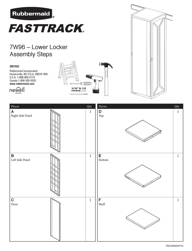
Rubbermaid 1Q06 User manual

Rubbermaid

Rubbermaid 1Q06 User manual

Rubbermaid MAX Add-On Closet Organizer User manual

Rubbermaid

Rubbermaid MAX Add-On Closet Organizer User manual

Rubbermaid 1T00 User manual

Rubbermaid

Rubbermaid 1T00 User manual
Popular Indoor Furnishing manuals by other brands

Sunnydaze Decor AJ-901 manual

Sunnydaze Decor

Sunnydaze Decor AJ-901 manual

Furniture of America CM3490T Assembly instructions

Furniture of America

Furniture of America CM3490T Assembly instructions

Habitat Large Trestle Table Desk 616/9639 Assembly instructions

Habitat

Habitat Large Trestle Table Desk 616/9639 Assembly instructions

Safavieh Furniture Armando SEA8019 quick start guide

Safavieh Furniture

Safavieh Furniture Armando SEA8019 quick start guide

Techni Mobili RTA-3805L Assembly instructions

Techni Mobili

Techni Mobili RTA-3805L Assembly instructions

Westwood Design RILEY Hutch Assembly instruction

Westwood Design

Westwood Design RILEY Hutch Assembly instruction

New Classic Furniture BRISTOL S1131-BS Assembly instructions

New Classic Furniture

New Classic Furniture BRISTOL S1131-BS Assembly instructions

SweetGo Abby Nightstand SG5011 Assembly instructions

SweetGo

SweetGo Abby Nightstand SG5011 Assembly instructions

SAFAVIEH COUTURE Petey SFV5109 manual

SAFAVIEH COUTURE

SAFAVIEH COUTURE Petey SFV5109 manual

Courtyard Creations KTS751G Assembly instructions

Courtyard Creations

Courtyard Creations KTS751G Assembly instructions

John Lewis ESSENCE OAK manual

John Lewis

John Lewis ESSENCE OAK manual

Bayside Furnishings Fontana FTN60C manual

Bayside Furnishings

Bayside Furnishings Fontana FTN60C manual

New Classic Furniture D1719-52S Assembly instructions

New Classic Furniture

New Classic Furniture D1719-52S Assembly instructions

AVALON FURNITURE B02920 D Assembly instructions

AVALON FURNITURE

AVALON FURNITURE B02920 D Assembly instructions

IKEA PS instructions

IKEA

IKEA PS instructions

Westwood Design Donnington Assembly instruction

Westwood Design

Westwood Design Donnington Assembly instruction

DURAVIT L-Cube LC 7650 Mounting instructions

DURAVIT

DURAVIT L-Cube LC 7650 Mounting instructions

Fischer mobel Kyoto 1815 Assembly instruction

Fischer mobel

Fischer mobel Kyoto 1815 Assembly instruction

manuals.online logo
manuals.online logoBrands
  • About & Mission
  • Contact us
  • Privacy Policy
  • Terms and Conditions

Copyright 2025 Manuals.Online. All Rights Reserved.