RUD SuperRotation ICE-LBG-SR Installation instructions

1
ICE-LBG-SR
RUD Ketten
Rieger & Dietz GmbH u. Co. KG
73428 Aalen
Tel. +49 7361 504-1370
Fax +49 7361 504-1171
www.rud.com
RUD-Art.-Nr.: 7904767-EN / 09.019
ICE-Load Ring for bolting
>ICE-LBG-SR<
SuperRotation®
Safety instructions
This safety instruction/declaration of the manufacturer has to be
kept on le for the whole lifetime of the product.
Translation of the original instructions
Load Ring in ICE-Pink - for bolting
ICE-LBG-SR
EG-Konformitätserklärung
entsprechend der EG-Maschinenrichtlinie 2006/42/EG, Anhang II A und ihren Änderungen
Hersteller: RUD Ketten
Rieger & Dietz GmbH u. Co. KG
Friedensinsel
73432 Aalen
Hiermit erklären wir, dass die nachfolgend bezeichnete Maschine aufgrund ihrer Konzipie-
rung und Bauart, sowie in der von uns in Verkehr gebrachten Ausführung, den grundle-
genden Sicherheits- und Gesundheitsanforderungen der EG-Maschinenrichtlinie
2006/42/EG sowie den unten aufgeführten harmonisierten und nationalen Normen sowie
technischen Spezifikationen entspricht.
Bei einer nicht mit uns abgestimmten Änderung der Maschine verliert diese Erklärung ihre
Gültigkeit.
Produktbezeichnung: Lastbock Super-Rotation
_____________________________________________
ICE-LBG-SR
_____________________________________________
Folgende harmonisierten Normen wurden angewandt:
DIN EN 1677-1 : 2009-03 DIN EN ISO 12100 : 2011-03
_________________ _________________
_________________ _________________
_________________ _________________
_________________ _________________
_________________ _________________
Folgende nationalen Normen und technische Spezifikationen wurden außerdem angewandt:
BGR 500, KAP2.8 : 2008-04
_________________ _________________
_________________ _________________
_________________ _________________
_________________ _________________
_________________ _________________
Für die Zusammenstellung der Konformitätsdokumentation bevollmächtigte Person:
Michael Betzler, RUD Ketten, 73432 Aalen
Aalen, den 26.09.2016 Dr.-Ing. Arne Kriegsmann,(Prokurist/QMB)
_____________________________________________
Name, Funktion und Unterschrift Verantwortlicher
EC-Declaration of conformity
According to the EC-Machinery Directive 2006/42/EC, annex II A and amendments
Manufacturer: RUD Ketten
Rieger & Dietz GmbH u. Co. KG
Friedensinsel
73432 Aalen
We hereby declare that the equipment sold by us because of its design and construction,
as mentioned below, corresponds to the appropriate, basic requirements of safety and
health of the corresponding EC-Machinery Directive 2006/42/EC as well as to the below
mentioned harmonized and national norms as well as technical specifications.
In case of any modification of the equipment, not being agreed upon with us, this declara-
tion becomes invalid.
Product name: Load ring Super-Rotation
_____________________________________________
ICE-LBG-SR
_____________________________________________
The following harmonized norms were applied:
DIN EN 1677-1 : 2009-03 DIN EN ISO 12100 : 2011-03
_________________ _________________
_________________ _________________
_________________ _________________
_________________ _________________
_________________ _________________
The following national norms and technical specifications were applied:
BGR 500, KAP2.8 : 2008-04
_________________ _________________
_________________ _________________
_________________ _________________
_________________ _________________
_________________ _________________
Authorized person for the configuration of the declaration documents:
Michael Betzler, RUD Ketten, 73432 Aalen
Aalen, den 26.09.2016 Dr.-Ing. Arne Kriegsmann,(Prokurist/QMB)
_____________________________________________
Name, function and signature of the responsible person
EN

2ICE-LBG-SR
Please read user instruction before initial
operation of the bolt-on lifting point ICE-LBG-
SR. Make sure that you have comprehend
all subjected matters.
Non observance can lead to serious per-
sonal injuries and material damage and
eliminates warranty.
In doubt or in misconception please note
that the German version of this document
is decisive.
1 Safety instructions
ATTENTION
Wrong assembled or damaged ICE-LBG-
SR as well as improper use can lead to
injuries of persons and damage of objects
when load drops.
Please inspect all ICE-LBG-SR before
each use.
• Remove all body parts (fingers, hands, arms,
etc.) out of the hazard area (danger of crushing
or squeezing) during the lifting process.
• The ICE-LBG-SR must be used only by authorised
and trained people in adherence to BGR/DGUV
regulations 100-500, Chapter 2.8 and, outside
Germany, when observing the relevant specic
national regulations.
• Do not exceed the working load limit (WLL) indi-
cated on the lifting point.
• Only original ICE-Bolts from RUD must be used.
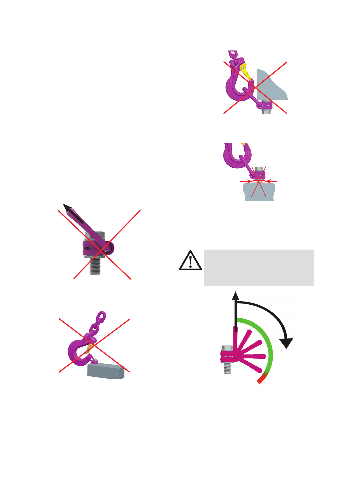
• ICE-LBG-SR must be rotatable in the screwed tight
status through 360 °.
• No technical alterations must be implemented on
the ICE-LBG-SR.
• No people may stay in the danger zone.
• Jerky lifting (strong impacts) should be prevented.
• Always ensure a stable position of the load when
lifting. Swinging must be prevented.
• Damaged or worn ICE-LBG-SR must never be
utilised.
2 Intended use
ICE-LBG-SR lifting points must only be attached at
a load or used at load accepting means.
Their usage is intended to be used as lifting means.
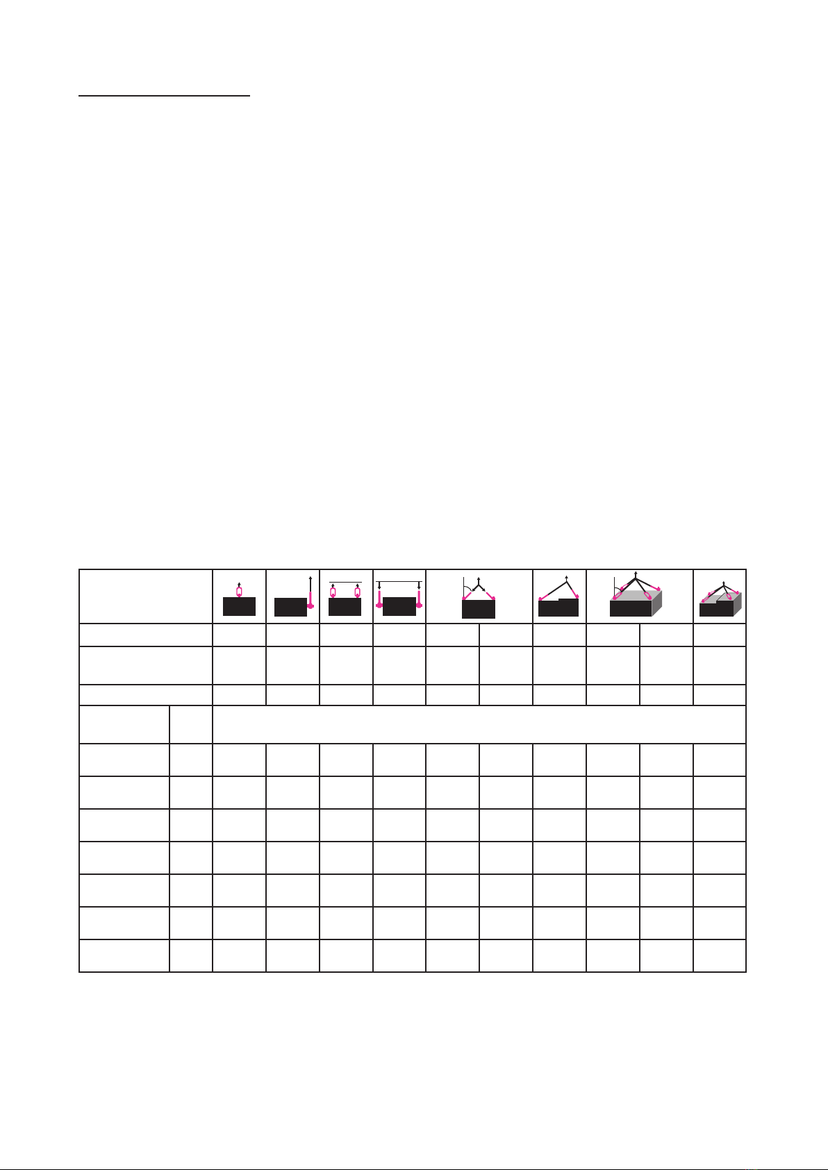
ICE-LBG-SR are suitable to turn and ip loads. Please
observe to this the permissible load directions.
RUD ICE-LBG-SR lifting points can also be used as
lashing points for xing lashing means.
ICE-LBG-SR lifting points must only be used in the
here described operation purpose.
3 Assembly- and instruction manual
3.1 General information
• ICE-LBG-SR can be used for ipping and turning
of loads. Please observe the hints at chapter 3.2
Hints for the assembly.
• Eects of temperature:
The WLL of the ICE-LBG-SR lifting points must be
reduced as follows:
-40°C up to 100°C no reduction
100°C up to 200°C minus 15 % (212 up to 392°F)
200°C up to 250°C minus 20 % (392 up to 482°F)
250°C up to 300°C minus 25 % (482 up to 572°F)
Temperatures above 300°C (572°F) are not per-
mitted!
Please observe the maximum usage temperature
of the supplied nuts (optionally):
• Lock nuts acc. to DIN EN ISO 7042 (DIN 980)
must be used to max. +150° C (302°F)
• Collar nuts acc. to DIN 6331 can be used up
to +300°C (572°F). In addition to that observe
the reduction factor
• RUD-Lifting points must not be used under chemi-
cal inuences such as acids, alkaline solutions and
vapours e.g. in pickling baths or hot dip galvanising
plants. If this cannot be avoided, please contact the
manufacturer, indicating the concentration, period
of penetration and temperature of use.
• The place where the ICE-LBG-SR lifting points are
xed should be clearly marked with colour.
• RUD ICE-LBG-SR lifting points from RUD are
supplied with a crack test inspected hexagon bolt
(length up to Lmax, see table 3).
M8-M24: ICE-Bolt
M30: 10.9 bolt
ATTENTION
Use only the appropriate strength class of bolt, for
each specic size. For sizes M8-M24, only original
RUD-ICE-Bolt must be used.
• Original bolts (ICE bolt and 10.9 bolts) are available
as a spare part from RUD.
• When using 10.9 bolts of the size M30 from other
suppliers, make sure that they have been 100 %
inspected in regards of cracks. A written conrma-
tion of the absence of cracks must be added to the
documentation.
The middle notch toughness at the lowest appro-
ved use temperature must be at least 36 J. This
is required for the test principles for GS OA 15-04
lifting points.
HINT
The dismantling / assembling for the ex-
change or inspecting of the bolt may only be
executed by a competent person (compare
with Section 3.4 Dismantling / Assembling
the RUD bolt).
• Versions
• The metric vario length can either be equipped
with a washer and a crack detected nut acc. to
DIN EN ISO 7042 or with a collar nut acc. to
DIN 6331.

3
ICE-LBG-SR
• If the VLBG is used exclusively for lashing, the va-
lue of the working load limit can be doubled.
LC = permissible lashing capacity = 2 x WLL
HINT
If the ICE-LBG-SR is or was used as a
lashing point, it must not be used for lifting
later on!
3.2 Hints for the assembly
Basically essential:
• The material construction to which the lifting point
will be attached should be of adequate strength to
withstand forces during lifting without deformation.
The German testing authority BG/DGUV, recom-
mends the following minimum for bolt lengths:
1x M in steel (minimum quality S235JR [1.0037])
1.25x M in cast iron (however when castings of
lower strength (<200 MPa) are used the
thread engagement has to be at least
1.5 x d)
2x M in aluminum alloys
2.5x M in light metals of low strength
(M = thread size, e.g. M20)
• When lifting light metals, nonferrous heavy metals
and gray cast iron the thread has to be chosen in
such a way that the working load limit of the thread
corresponds to the requirements of the respective
base material.
• ICE-LBG-SR lifting points must be positioned at
the load in such a way that improper loading like
turning or twisting of the load will be avoided:
• For single leg lifts: Load ring should be
positioned vertically above the centre of
gravity.
• For two leg lifts: Lifting points must be
positioned on both sides and above the centre
of gravity.
• For three and four leg lifts: Lifting points
should be arranged equally in a plain level
around centre of gravity.
• Symmetry of loading:
Determine the working load limit of each individual
RUD lifting point for symmetrical and unsymme-
trical loading according to the following physical
formula:
WLL = working load limit (kg)
G = load weight (kg)
n = number of load bearing legs
ß = angle of inclination of the chain to the vertical
WLL=G
n x cos ß
Number of load bearing strands
Symetrical Unsymetrical
Double leg 2 1
Three/four leg 3 1
Table 1: Load bearing strands (compare also with
Table 2)
HINT
With unsymmetrical loads, the WLL of each
Lifting Point must be the same as the
weight of the load.
• A plane bolt-on surface (ØD, table 3) with a
perpendicular thread hole must be guaranteed.
The thread must be carried out acc. to DIN 76
(countersink max. 1.05xd).
The holes must be drilled with a sucient depth in
order to guarantee compatibility with the supporting
surface. Machine through holes up to DIN EN
20273-middle.
• The ICE-LBG-SR must be rotatable by 360° when
installed. Please observe the following:
• For a one-time transport, or a turning action
and ipping of a load, tightening by hand with
a spanner is sucient. Lifting point must be
fully engaged into thread hole and the bearing
surface must sit properly at the bolt-on area of
the load.
• For long term application the ICE-LBG-SR
must be tightened with torque according to
table 3 (+/- 10 %).
• If used multiple times for transporting, tur-
ning or ipping under load, it is necessary to
tighten the ICE-LBG-SR with a torque moment
(+/- 10 %) according to table 3.
• With shock loading or vibrations, especially at
through hole fixtures with a nut at the end of
the bolt, accidential release can occure.
Securing possibilities: Observe torque moment,
use liquid securing glue f.e. Loctite (can be adap-
ted to the usage, observe manufacturer hints) or
assemble a form closure bolt locking device f.e. a
castle nut with cotter pin, locknut etc.
• Finally check the proper assembly (see chapter 4
Inspection / repair).
3.3 Hints for the usage
3.3.1 General information for the usage
• Always regularly observe the appearance of the
whole lifting point (e.g. xed lifting point/slings)
before using it (secured bolt seat, strong corrosion,
cracks on load-bearing parts, deformations). Refer
to chapter 4 Inspection / repair.
ATTENTION
Wrong assembled or damaged ICE-LBG-
SR as well as improper use can lead to
injuries of persons and damage of objects
when load drops.
Please inspect all ICE-LBG-SR carefully
before each use.

4ICE-LBG-SR
• RUD components are designed according to DIN
EN 818 and DIN EN 1677 for a dynamic load of
20,000 load cycles.
• Keep in mind that several load cycles can occur
with a lifting procedure
• Keep in mind that, due to the high dynamic
stress with high numbers of load cycles, that
there is a danger that the product will be da-
maged
• The BG/DGUV recommends: For higher dyna-
mic loading with a high number of load cycles
(continuous operation), the working load stress
must be reduced according to the driving mecha-
nism group 1Bm (M3 in accordance with DIN EN
818-7). Use a lifting point with a higher working
load limit.
• When attaching and removing the lifting means
(e.g. lifting chains), crushing, shearing, trapping and
impact spots must be prevented.
• Prevent damage being caused to the lifting means
by loading at sharp edged.
• Set the suspension ring of the ICE-LBG-SR in the
direction of force before attaching the lifting means.
F
Pic. 1: Forbidden loading direction
• Keep in mind that the lifting means in the ICE-LBG-
SR must be freely movable.
Pic. 2: Use only suitable lifting means for hanging or
hooking into the ICE-LBG-SR
• A bending load of the suspension ring is not per-
mitted!
Pic. 3: The load must move freely and must not be
loaded at edges
• Always completely engage the lifting point.
Pic. 4: The lifting point must be completely screwed in.
3.3.2 Allowed lifting and turning operations
• Turning operations where the load ring will be tur-
ned into the load direction.
WARNING
The load ring must not support itself at
edges or other attachments.
Also the attached lifting mean must not
touch the head of the bolt.
F
Pic. 5: Pivoting in load direction

5
ICE-LBG-SR
• Turning operations where the ICE-LBG-SR will be
turned around the bolt axle.
WARNING
Observe the requested torque value before
each lifting or turning operation.
3.4 Dismantling / Assembling the RUD bolt
HINT
The dismantling / assembling and/or the
exchange of the RUD bolt must only be
executed by a competent person!
3.4.1 Dismantling the bolt of the
ICE-LBG-SR M8-M30
1. Position ICE-LBG-SR with the thread end upwards
at the bushing on the top of the bench vice without
clamping the hexagon head of the bolt.
2. Slightly hit the bolt from the top to drive it out from
the bushing (Pic. 6).
Pic. 6: Dismantling position of the ICE-LBG-SR
3.4.2 Assembling the bolt of the
ICE-LBG-SR M8-M10
HINT
Only the appropriate strength class of bolt
for each specic size must be used!
M8-M10: ICE-Bolt only!
1. Insert the bolt into the drill hole in the socket until
the retaining ring is positioned on the socket.
2. Squeeze the retaining ring together with at pliers
so that it sits deeply in the groove of the nut.
3. Now insert the bolt with light hits with a hammer
fully into the socket.
4. Finally, control the tightness of the bolt. The bolt
must be easily rotatable by 360°.
3.4.3 Assembling the bolt for
ICE-LBG-SR M12-M30
HINT
Only the stated strength of class for the
respective size of the bolts must be used!
M12-M24: ICE-Bolt | M30: 10.9
1. Insert the bolt into the bushing at the tapered end,
where the chamfer is (refer to Pic. 7).
Pic. 7: ICE-LBG-SR in sectional view.
The insertion chamfer is visible on top of the bushing
2. Insert the bolt into the socket in such a way that
the retaining ring is circumferential deepened in
the socket and seated (refer to Pic. 8).
TIP
Turn the bolt a few times under slight pres-
sure so that it is centered in the retaining
ring!
Pic. 8: Retaining ring positioned as circumferential
in the recess
3. Use a light tap on the head of the bolt so that the
bolt can be assembled up to the end stop of the
bolt head on the socket.
4. Finally, control the tightness and seating of the bolt.
The bolt must be easily rotatable by 360°.

6ICE-LBG-SR
4 Inspection / repair
4.1 Hints for periodical inspections
The operator must determine and specify the nature
and scope of the required tests as well as the periods
of repeating tests by means of a risk assessment (see
sections 4.2 and 4.3).
The continuing suitability of the anchor point must be
checked at least 1x year by an expert.
Depending on the usage conditions, f.e. frequent
usage, increased wear or corrosion, it might be ne-
cessary to check in shorter periods than one year. The
inspection has also to be carried out after accidents
and special incidents.
4.2 Test criteria for the regular visual
inspection by the user
• Correct bolt sizes and nut sizes, bolt quality and
screw-in lengths
• Always observe tightness of the bolts
→ inspect the torque
• Comprehensiveness of the lifting point.
• Comprehensive, legible load-bearing information
as well as the manufacturer‘s identication mark.
• Deformations on load-bearing parts such as basic
body, hanging or hooking in suspension ring and
bolt
• Mechanical damage such as signicant notches,
particularly in areas subject to tensile stress.
• Easy rotation of the ICE-LBG-SR must be ensured
4.3 Additional test criteria for the
competent person / repair worker
• Cross-section alterations caused by wear > 10 %.
• Strong corrosion
• function of and damage to the bolts, nut as well a
the screw thread (disassembly / assembly of the
bolt see section 3.4).
• further checks may be required, depending on
the result of the risk assessment (e.g. testing for
cracks in load-bearing parts).
Table 2: WLL in [t]
Method of lift
Number of legs 1 1 2 2 2 2 2 3/4 3/4 3/4
Angle of inclination 0° 90° 0° 90° 0-45° 45-60° un-
sym.
0-45° 45-60° un-
sym.
Factor 1 1 2 2 1.4 1 1 2.1 1.5 1
Type Th-
read
For the max. total load weight >G< in metric tons [t],
tightened and adjusted to force direction
ICE-LBG-SR
0.6 t M8 0.6 0.6 1.2 1.2 0.84 0.6 0.6 1.26 0.9 0.6
ICE-LBG-SR
0.9 t M10 0.9 0.9 1.8 1.8 1.3 0.9 0.9 1.9 1.35 0.9
ICE-LBG-SR
1.35 t M12 1.35 1.35 2.7 2.7 1.9 1.35 1.35 2.84 2 1.35
ICE-LBG-SR
2.5 t M16 2.5 2.5 5 5 3.5 2.5 2.5 5.25 3.75 2.5
ICE-LBG-SR
3.5 t M20 3.5 3.5 7 7 4.9 3.5 3.5 7.35 5.25 3.5
ICE-LBG-SR
4.5 t M24 4.5 4.5 9 9 6.3 4.5 4.5 9.5 6.75 4.5
ICE-LBG-SR
6.7 t M30 6.7 6.7 13.4 13.4 9.5 6.7 6.7 14.0 10 6.7
G
GG
A
G
G
A
G
G
β
G
β

7
ICE-LBG-SR
Type WLL
[t]
weight
[kg/pc.]
T
[mm]
A
[mm]
B
[mm]
C
[mm]
D
[mm]
E
[mm]
F
[mm]
G
[mm]
H
[mm]
I
[mm]
K
[mm]
L
[mm] MN
[mm]
SW
[mm]
ISK
[mm]
Torque
[Nm] Ref. No.
ICE-LBG-SR Load ring for bolting Super Rotation®– metric
ICE-LBG-SR 0.6 t M8 0.6 0.3 75 30 52 34 24 40 10 29 11 75 43 40 M8 32 13 5 30 8504284
ICE-LBG-SR 0.9 t M10 0.9 0.31 75 30 52 34 24 39 10 29 15 75 43 44 M10 32 17 6 60 8504285
ICE-LBG-SR 1.35 t M12 1.35 0.34 75 32 52 34 26 38 10 29 18 75 43 47 M12 32 19 8 150 8504286
ICE-LBG-SR 2.5 t M16 2.5 0.52 85 34.5 56 40 30 39 13.5 36 22 86 46 58 M16 38 24 10 150 8504287
ICE-LBG-SR 3.5 t M20 3.5 1.3 110 54 82 60 45 53 17 43 32 113 61 75 M20 48 30 12 400 8504288
ICE-LBG-SR 4.5 t M24 4.5 1.4 125 54 82 60 45 66 17 43 37 130 76 80 M24 48 36 14 760 8504289
ICE-LBG-SR 6.7 t M30** 6.7 3.2 147 63 102 69 55 66 22.5 61 49 151 79 110 M30 66 46 17 1000 8504290
Type WLL weight T A B C D E F G H I K L M N SW ISK Torque Ref. No.
ICE-LBG-SR –metr., Länge nach Wunsch // metr., longer vario bolt
ICE-LBG-SR 0.6 t M8 0.6 * 75 30 52 34 24 40 10 29 8-76 75 43 37-105 M8 32 13 5 30 8600500
ICE-LBG-SR 0.9 t M10 0.9 * 75 30 52 34 24 39 10 29 10-96 75 43 39-125 M10 32 17 6 60 8600501
ICE-LBG-SR 1.35 t M12 1.35 * 75 32 52 34 26 38 10 29 12-116 75 43 41-145 M12 32 19 8 150 8600502
ICE-LBG-SR 2.5 t M16 2.5 * 85 34.5 56 40 30 39 13.5 36 16-149 86 46 50-185 M16 38 24 10 150 8600504
ICE-LBG-SR 3.5 t M20 3.5 * 110 54 82 60 45 53 17 43 20-187 113 61 65-230 M20 48 30 12 400 8600506
ICE-LBG-SR 4.5 t M24 4.5 * 125 54 82 60 45 66 17 43 24-222 130 76 69-265 M24 48 36 14 760 8600508
ICE-LBG-SR 6.7 t M30** 6.7 * 147 63 102 69 55 66 22.5 61 30-279 151 79 90-340 M30 66 46 17 1000 8600510
Table 3: Dimensioning (SW = wrench size / ISK = internal hexagon) * = weight depends on design specics / ** = bolt with quality grade 10.9
Subject to technical alterations

8ICE-LBG-SR
Table of contents
Other RUD Industrial Equipment manuals
Popular Industrial Equipment manuals by other brands

ABB
ABB MNS R System guide

Parker
Parker J Series Maintenance Bulletin

TB Wood's
TB Wood's Form-Flex HH Series installation instructions

Rockwell Automation
Rockwell Automation Allen-Bradley 1719 Ex I/O installation instructions

3M
3M 3M-Matic 300cf Instructions and parts list

ABB
ABB HT610733 Operation manual