RUD VWBM User manual

1
VWBM
RUD Ketten
Rieger & Dietz GmbH u. Co. KG
73428 Aalen
Tel. +49 7361 504-1370
Fax +49 7361 504-1460
www.rud.com
RUD-Art.-Nr.: 7909684-EN / 05.021
Load ring
with internal thread
> VWBM <
Safety instructions
This safety instruction/declaration has to be kept on le
for the whole lifetime of the product
and forwarded with the product.
TRANSLATION OF THE ORIGINAL SAFETY INSTRUCTION
VWBM
Load ring with internal thread
EN
EG-Konformitätserklärung
entsprechend der EG-Maschinenrichtlinie 2006/42/EG, Anhang II A und ihren Änderungen
Hersteller:
RUD Ketten
Rieger & Dietz GmbH u. Co. KG
Friedensinsel
73432 Aalen
Hiermit erklären wir, dass die nachfolgend bezeichnete Maschine aufgrund ihrer Konzipie-
rung und Bauart, sowie in der von uns in Verkehr gebrachten Ausführung, den grundle-
genden Sicherheits- und Gesundheitsanforderungen der EG-Maschinenrichtlinie
2006/42/EG sowie den unten aufgeführten harmonisierten und nationalen Normen sowie
technischen Spezifikationen entspricht.
Bei einer nicht mit uns abgestimmten Änderung der Maschine verliert diese Erklärung ihre
Gültigkeit.
Produktbezeichnung: Wirbelbock VWBM
_____________________________________________
_____________________________________________
Folgende harmonisierten Normen wurden angewandt:
DIN EN 1677-1 : 2009-03 DIN EN 1677-4 : 2009-03
_________________ _________________
DIN EN ISO 12100 : 2011-03
_________________ _________________
_________________ _________________
_________________ _________________
_________________ _________________
Folgende nationalen Normen und technische Spezifikationen wurden außerdem angewandt:
DGUV-R 109-017 : 2020-12
_________________ _________________
_________________ _________________
_________________ _________________
_________________ _________________
_________________ _________________
Für die Zusammenstellung der Konformitätsdokumentation bevollmächtigte Person:
Michael Betzler, RUD Ketten, 73432 Aalen
Aalen, den 14.04.2021 Hermann Kolb, Bereichsleitung MA
_____________________________________________
Name, Funktion und Unterschrift Verantwortlicher
EC-Declaration of conformity
According to the EC-Machinery Directive 2006/42/EC, annex II A and amendments
Manufacturer: RUD Ketten
Rieger & Dietz GmbH u. Co. KG
Friedensinsel
73432 Aalen
We hereby declare that the equipment sold by us because of its design and construction,
as mentioned below, corresponds to the appropriate, basic requirements of safety and
health of the corresponding EC-Machinery Directive 2006/42/EC as well as to the below
mentioned harmonized and national norms as well as technical specifications.
In case of any modification of the equipment, not being agreed upon with us, this declara-
tion becomes invalid.
Product name: Load ring VWBM
_____________________________________________
_____________________________________________
The following harmonized norms were applied:
DIN EN 1677-1 : 2009-03 DIN EN 1677-4 : 2009-03
_________________ _________________
DIN EN ISO 12100 : 2011-03
_________________ _________________
_________________ _________________
_________________ _________________
_________________ _________________
The following national norms and technical specifications were applied:
DGUV-R 109-017 : 2020-12
_________________ _________________
_________________ _________________
_________________ _________________
_________________ _________________
_________________ _________________
Authorized person for the configuration of the declaration documents:
Michael Betzler, RUD Ketten, 73432 Aalen
Aalen, den 14.04.2021 Hermann Kolb, Bereichsleitung MA
_____________________________________________
Name, function and signature of the responsible person

2VWBM
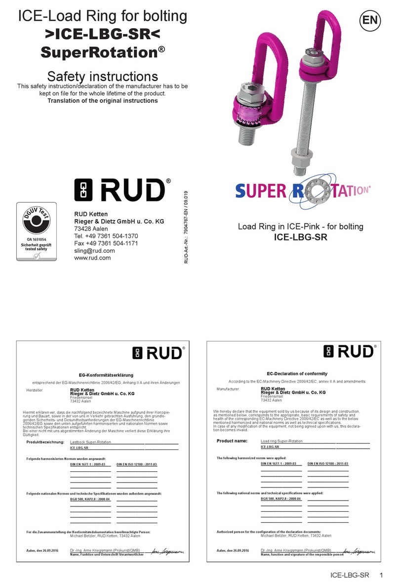
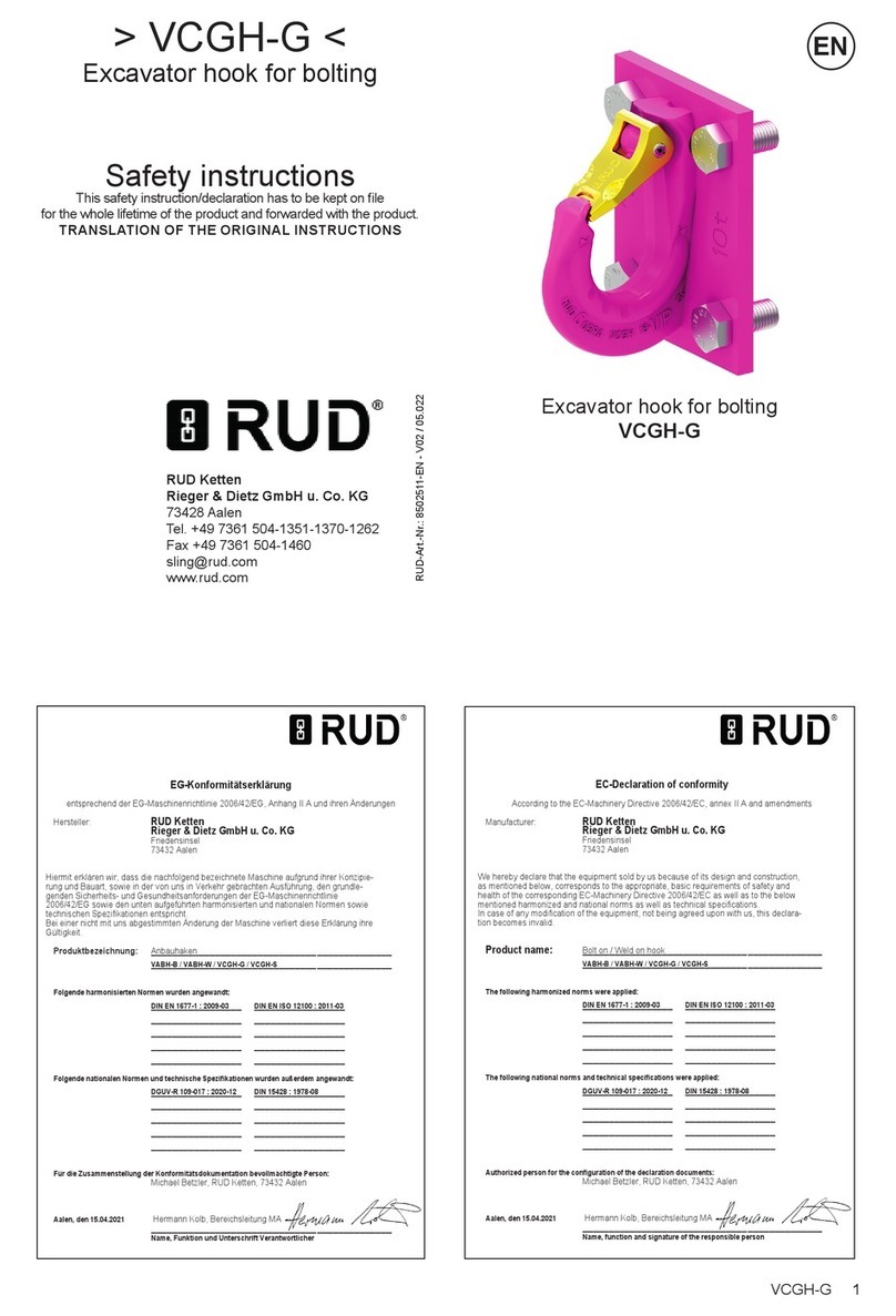
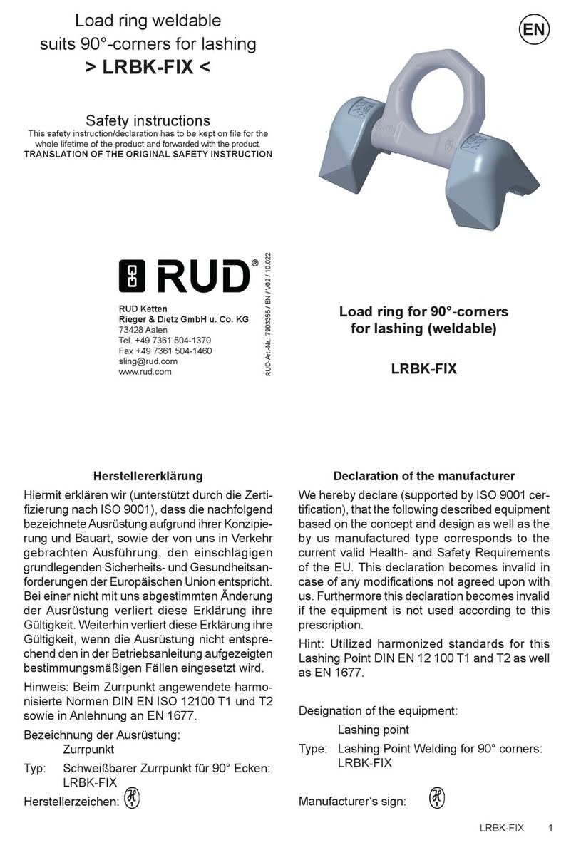
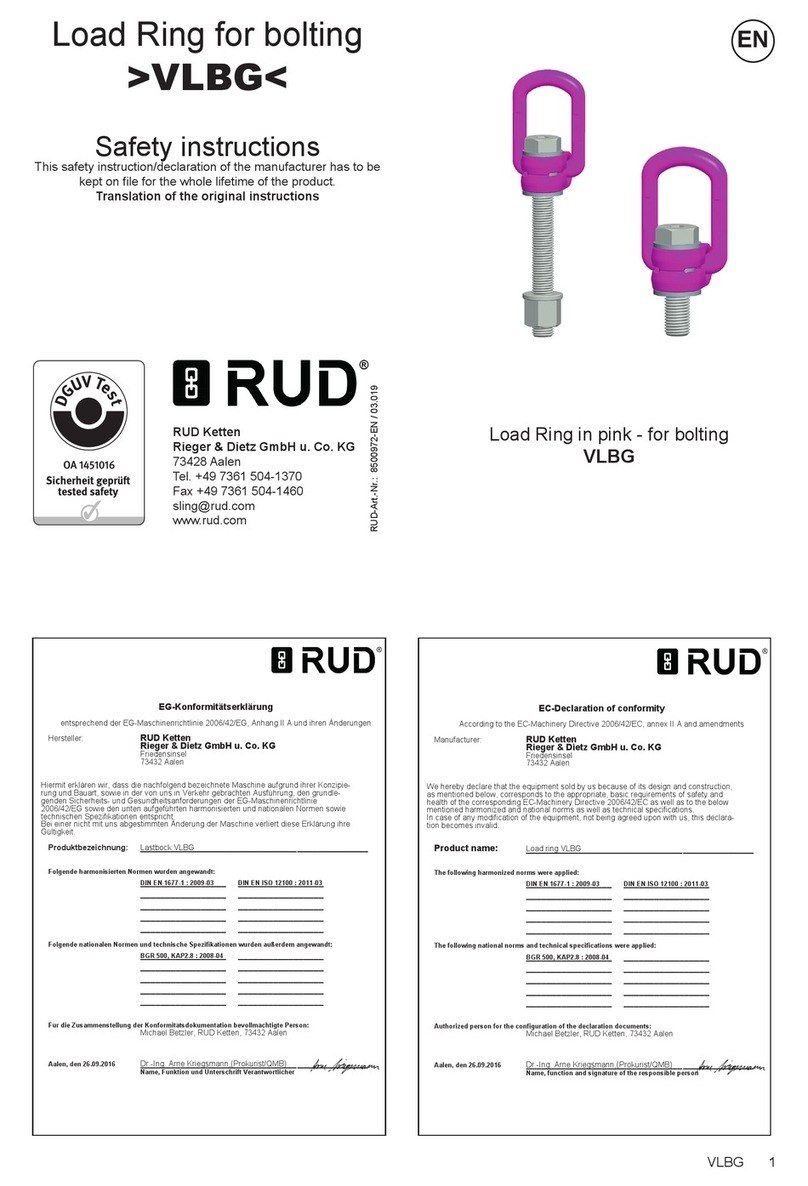
This user manual contains information
about the correct and safe use of RUD
VWBM load rings.
Before initial usage of the RUD VWBM load
rings, please read carefully and in full the
safety instructions.
Make sure you have understood eve-
rything. If you need further information,
ask your RUD retailer or RUD application
engineer.
RUD VWBM load rings have been desi-
gned for commercial use.
Failure to observe the instructions can result
in physical injury or material damage and
means that the warranty no longer applies.
1 Safety instructions
WARNING
Wrong assembled or damaged Lifting
Points as well as improper use can lead to
injuries of persons and damage of objects
when load drops.
Please inspect all Lifting Points before
each use.
• Keep all body parts like ngers, hands, arms, etc. out
of the hazardous area during the lifting operation.
• Attention: When suspension ring pivots there is a
risk of pinching.
• The RUD VWBM must only be used by authorized
and trained persons in adherence with DGUV Regu-
lations 109-017 and according to the country-specic
provisions and regulations outside Germany.
• Do not exceed the working load limit (WLL) indica-
ted on the lifting point (except vertical loading - see
Table 3).
• Continuous rotary movement under load is not
permissible. RUD VWBM can be rotated 90° to the
bolt-in direction under nominal load capacity.
• The RUD VWBM load rings have to be rotatable
by 360° when securely screwed in.
• The ball bearing resp. the bush bearing disc must
not be disassembled.
• The load ring must not be bend.
• No technical alterations must be implemented on
the VWBM.
• No people may stay in the danger zone.
• Jerky lifting (strong impacts) should be prevented.
• Always ensure a stable position of the load when
lifting. Swinging must be prevented.
• Damaged or worn VWBM must never be utilised.
2 Intended use
RUD VWBM load rings must only be used for the
assembly at the load or at lifting means.
They are intended for suspending slings and can be
rotated 90° to the screw-in direction under nominal
load capacity. Continuous rotary movement under
load is not permissible.
HINT
Observe the specications for turning in
Chapter 3.3.2.
RUD VWBM load rings can also be used as lashing
points to attach lashing means.
RUD VWBM load rings must only be used in the
hereby described operation purpose.
3 Assembly- and instruction manual
3.1 General information
• Capability of temperature usage:
Usage at higher temperatures is not recommended
due to the grease lling in the ball bearing. Should
this though be necessary, the working load limit
(WLL) of the VWBM must be reduced as follows:
-40°C up to 100°C no reduction
100°C up to 200°C minus 15 %
200°C up to 250°C minus 20 %
250°C up to 350°C minus 25 %
Temperatures exceeding 350°C are prohibited!
• RUD VWBM load rings must not be used with
aggressive chemicals such as acids, alkaline so-
lutions and their vapours.
• Please mark mounting position of lifting point with
a coloured contrast paint for better visibility.
CONTENT
1 Safety instructions 2
2 Intended use 2
3 Assembly- and instruction manual 2
3.1 General information ..................................................2
3.2 Hints for the assembly ..............................................3
3.3 User instructions.......................................................4
3.3.1 General information regarding use .............4
3.3.2 Rotating and turning of loads ......................5
4 Inspection / Repair / Disposal 5
4.1 Hints for periodical inspections.................................5
4.2 Test criteria for the regular visual inspection
by the user................................................................6
4.3 Additional test criteria for the
competent person / repair worker.............................6
4.4 RUD BLUE-ID SYSTEM...........................................6
4.5 Disposal....................................................................6
5 Hints for repairing 6
6 Tables 7

3
VWBM
3.2 Hints for the assembly
Basically essential:
• The material construction to which the lifting point
will be attached should be of adequate strength to
withstand forces during lifting without deformation.
• Only insert the RUD VWBM with the correct th-
reads, which must correspond at least to class of
strength 10.9.
HINT
Lower classes of strength of bolts or threaded
bolts reduce the WLL!
• Minimum screw-in:
Fmin = 1 x M
• Maximum screw-in:
Fmax = 1,6 x M
• Drilling depth in VWBM:
H = 1,7 x M
• Internal thread length
F = 1,25 x M
F, H and M see Table 2
Pic. 1: Thread details
WARNING
The screw-in length must never be larger
than size H because otherwise the thread
will impact the base of the VWBM and the
support of the VWBM for the load is im-
paired (Pic. 1). See also section 1 Safety
instructions!
• When using threads (e.g. threaded bolts, bolts)
provided yourself, check they are 100% free of
cracks (a written conrmation from the supplier
must be added to the VWBM documents).
• The average notch bar impact test at the lowest
permitted usage temperature must be at minimum
36 J. This specication is required as per the test
criteria for lifting points GS OA 15-04.
• Ensure that the threads used have the same thread
type, thread size as the VWBM used. The VWBM
is labelled with the thread type and size (Pic. 2).
Pic. 2: Component labelling VWBM
• Ensure that the thread length of the thread used
(e.g. threaded bolt, screws) corresponds to the
requirements regarding minimum and maximum
screw-in depth for the application.
• The position of the lifting points must be carried
out in such a way that unintended movement like
turning or ipping will be avoided.
• For single leg lifts, the lifting point should be
vertically above the centre of gravity of the
load.
• For two leg lifts, the lifting points must be
equidistant to/or above the centre of gravity
of the load.
• For three and four leg lifts, the lifting points
should be arranged symmetrical around the
centre of gravity, in the same plane if possible.
• Load symmetry:
Determine the necessary WLL of each lifting point
for a symmetrical or an unsymmetrical load by
using the following physical calculation formula:
WLL = necessary WLL of lifting point /
single strand (kg)
G = weight of load (kg)
n = number of load bearing strands
ß = inclination angle of single strand
WLL=G
n x cos ß
Symmetric Unsymmetric
two leg 2 1
three / four leg 3 1
Table 1: Load bearing strands
• The protruding thread length must be adjusted to
the screw-in situation so that contact surface of the
lifting point can lie at (Pic. 5).
There must be enough space between the end of
the thread and the base of the internal thread in
order to allow tightening.
• A plane bolt-on surface with a minimum ØD (Table
2) must be guaranteed (Pic. 6).
• A threaded or through hole xture at right-angles
to the contact surface must be guaranteed.

4VWBM
• For through hole screw connections, make sure that
the contact surface of the screw head is sucient
for the load. Complete the through hole xture for
the threat in the load according to DIN EN 20273
middle or ne.
• Due to the ball bearing and the bush bearing it is
sucient for a single lift to tighten the VWBM until
the bearing surface has support by using a spanner
acc. to DIN 895 resp. DIN 894, without using an
extension.
However, the torque moment according to Table 2
(+/- 10 %) must not be exceeded. We generally re-
commend assembly with a suitable torque wrench.
If the VWBMV shall permanently installed at the
load, tensioning must be carried out with a torque
(+/- 10 %) according to Table 2.
ATTENTION
Disassembly of the ball bearing resp. the
bush bearing disc carried out by the user
is forbidden.
• The VWBM must not be loaded with the Manufacturing
Proof Force MPF (2.5 x WLL). Should at the production
of lifting means or similar products, a singular proof
loading be necessary, please ask RUD in advance.
• Check nally the correct assembly (see chapter 4
Inspection / Repair / Disposal).
3.3 User instructions
3.3.1 General information regarding use
• Before use (e.g. by the user), inspect the entire lif-
ting point (secure thread t strong corrosion, cracks
in supporting parts, deformations). See section 4
Inspection / Repair / Disposal.
ATTENTION
Wrong assembled or damaged lifting
means as well as improper use can lead to
injuries of persons and damage of objects
when load falls.
Please inspect all lifting points before each
use.
• RUD components are designed according to DIN
EN 818 and DIN EN 1677 for a dynamic load of
20,000 load cycles.
• Keep in mind that several load cycles can occur
with a lifting procedure.
• Keep in mind that, due to the high dynamic stress
with high numbers of load cycles, that there is a
danger that the product will be damaged.
• The BG/DGUV recommends: For higher dy-
namic loading with a high number of load cycles
(continuous operation), the working load stress
must be reduced according to the driving mecha-
nism group 1Bm (M3 in accordance with DIN EN
818-7). Use a lifting point with a higher working
load limit.
• The VWBM are suitable for turning and rotating
loads.
• During rotation and turning, all positions of the
suspension link can occur.
• The nominal load capacity is indicated on the com-
ponent. The nominal load capacity corresponds to
the most unfavorable possible application ,resp.
worst case scenario (see Pic. 9 – Part X).
• When turning under 90° to the bolt-in axis (Pic. 9
Part X part Y) the load capacity per VWBM is limited
to the nominal load capacity (WLL).
• With the suspension ring manually aligned (see Pic.
9- Part Y) the higher () values from Table 3 can be
applied if no rotation or turning is performed.
ATTENTION
Pay attention during the usage that the load
type will not be change.
If the VWBM will be loaded only perpendicular (in
axial direction of the thread, see Pic. 9 - Part Z), the
corresponding WLL values from Table 3 (inclination
angle 0°) can be used.
• The ring of the manually adjusted VWBM can be
pivoted by approx. 230° (Pic. 3).
ATTENTION
The suspension ring resp. the attached
lifting mean must rotate and pivot without
interference during lifting and must neither
have support at the load edge nor at the
bottom part of the VWBM (Pic. 4).
Pic. 3: Pivoting area Pic. 4: Forbidden
contact or support at/or
with edge
• Only use appropriate lifting means for hinging in the
VWBM. The suspension ring must not be exposed
to bending load
• When lifting means (sling chains) are hinged or un-
hinged, no pinching, shearing or joint spots must occur
during the handling. Avoid damage of lifting means
resulting from sharp edges .
• Leave direct danger zone as far as possible.
• Watch always your hinged loads.
5
VWBM
• VWBM must have been fully bolted in.
Pic. 5: VWBM must have
been fully bolted in.
• Thread of the VWBM must be completely engaged
and the lifting point must be installed full-faced.
(The diameter of the bearing surface must be ≥ D
- see Table 2).
Pic. 6: The diameter of the
bearing surface must be ≥ D.
• Avoid impulsive and tiltful loading.
ATTENTION
Impulsive loading or vibration, especially
at through hole connections with nuts, can
lead to unintentional loosening.
Securing possibilities: liquid thread securing pro-
ducts f.e. Loctite (read manufacturer´s instruction)
or form closed bolt securing can be used. Secure
in general all lifting points which are installed per-
manently, e.g. with glue.
• Please observe for the whole lifting mean the RUD
sling chain safety instruction.
3.3.2 Rotating and turning of loads
Observe the following additional specications for
turning and rotating loads:
ATTENTION
The VWBM are suitable for turning and
rotating of loads.
However, a continuous rotating movement
under load is not permitted in any load
direction (Pic. 9).
ATTENTION
When using, take special care not to
change the load type.
HINT
To extend the service life, we recommend
the use of a VWBM with a higher load
capacity.
• When turning under 90° to the bolt-in axis (Pic. 9 Part
X and Y) the load capacity per VWBM is limited to the
nominal load capacity (Table 3: Columns with angle
of inclination 90°).
The nominal load capacity is indicated on the component
and included in the product designation (Table 2 and
Table 3: e.g. VWBM 1 t M16).
• When rotating below 90° to the bolt-in axis, the
increased load capacity „Y“ is not permissible (Pic.
9– Part Y / value in brackets in Table 3).
• When rotating exclusively perpendicular to the bolt
-in axis (Pic. 9 – Part Z), the corresponding load
capacity values from Table 3 (angle of inclination
0°) can be applied.
• For a single turning or reversing operation, tighte-
ning with an open-end wrench is sucient. Observe
section 3.2 Hints for the assembly.
• If the VWBM is to remain permanently attached to
a load for regular turning and reversing, a suitable
thread locking device must be used in addition to
the specied tightening torque (see Table 2 and
3.3 User instructions).
• Regularly check for repeated turning and twisting
with a VWBM:
• Ensure that the threads are rmly tightened.
• The bearing surface of the VWBM must lie fully
on the bolt-on surface.
• The maximum clearance between upper and
lower part of the VWBM must not be exceeded
(see 4.2)
• Further tests may be necessary, depending on
the result of the risk assessment.
• In addition, observe the notes from chapters 4.2
and 4.3.
4 Inspection / Repair / Disposal
4.1 Hints for periodical inspections
The operator must determine and specify the nature
and scope of the required tests as well as the periods
of repeating tests by means of a risk assessment (see
sections 4.2 and 4.3).
The continuing suitability of the lifting point must be
checked at least 1x year by an expert.
Depending on the usage conditions, f.e. frequent
usage, increased wear or corrosion, it might be
necessary to check in shorter periods than one year.
The inspection has also to be carried out after acci-
dents and special incidents.
The operator must specify the test cycles.

6VWBM
4.2 Test criteria for the regular visual inspection
by the user
• Correct thread size, thread quantity and screw-in
length.
• Solid thread xture - Inspection of bolting torque
• The bearing surface of the VWBM must lay plane
and holohedral on the bolting area.
• Completeness of the lifting point
• Complete, readable WLL statements as well as
manufacturer sign.
• Deformation at load bearing components like base
body, suspension ring and threads (e.g. threaded
bolts, screws).
• Mechanical damage, like strong notches, especially
in areas where tensile stress occurs.
• Locking screw at the side must be tightened.
• Easy turning without jerk between upper and base
part of the VWBM must be guaranteed.
• The maximum gap S between upper and base part
must not be exceeded (Pic. 7):
VWBM 0.6 t M12: Smax. 1.5 mm
VWBM 1 t M16: Smax. 1.5 mm
VWBM 1.8 t M20: Smax. 1.5 mm
Smax.
Pic. 7: Maximum gap Smax. between upper- and base part
4.3 Additional test criteria for the
competent person / repair worker
• Reduction of cross section caused by wear > 10 %,
or when the wear lenses have been reached in the
main load bearing directions
• Strong corrosion
• Function and damage of VWBM and the thread
(e.g. threaded bolts, screws).
• further checks may be required, depending on the
result of the risk assessment (e.g. testing for cracks
in load-bearing parts).
4.4 RUD BLUE-ID SYSTEM
The RUD BLUE-ID SYSTEM oers a convenient
overall solution for checking operating equipment.
RUD ID-POINT®RFID transponders with a uniquely
allocated identication number are press-tted as
standard in dened RUD products. In addition, RUD
oers you numerous possibilities to retrot compo-
nents safely and permanently with an RUD our trans-
ponders. This allows the simple and legally certain
identication of components without any mix-up.
In addition, the cloud-based software solution AYE-D.
NET oers the simplest documentation and manage-
ment of the test data. As a combination of testing,
administration and documentation software, AYE-D.
NET facilitates numerous possibilities in testing ad-
ministration and subsequent processes.
4.5 Disposal
Dispose worn out components / attachments or
packaging according to the local waste removal
requirements.
5 Hints for repairing
Repair work must only be carried out by a competent
person at RUD or by a RUD trained and authorized
service station, which has obtained the necessary
knowledge and skills.

7
VWBM
6 Tables
Pic. 8: Dimensioning
X Y Z
Applications -
90° to the bolt-in axis
Applications -
90° to the bolt-in
axis
Nominal
WLL
manual
adjustment
vertical
loading
(worst case scenario) (higher values in
brackets
possible depending
on usage)
(WLL acc. to
Table)
Pic. 9: Loading directions
Type WLL
[t]
A
[mm]
B
[mm]
C
[mm]
D
[mm]
E
(SW)
[mm]
F
[mm]
G
[mm]
H
[mm]
M
[mm]
T
[mm]
torque
[Nm]
weight
[kg/pc.]
Ref.-No. Pa-
cking
unit
VWBM 0.6 t M12 0,6 10 49 35 41 36 15 62 21 12 122 80 0.6 7909682 10
VWBM 1 t M16 1 13 46 38 46 41 20 73 27 16 131 150 0.9 7909683 10
VWBM 1.8 t M20 1.8 13 54 35 62 55 25 88 34 20 158 240 1.8 7911439 4
Table 2: Dimensioning Subject to technical alterations
HINT
Size F is the internal thread length
of the VWBM and is 1.25 x M.
Lifting method
G
G
G
G
G
G
G
G
Number of legs 1 2 1 2 2 2 2 3 / 4* 3 / 4* 3 / 4*
Inclination angle <ß 0° 0° 90° 90° 0-45° >45-60° Un-
symm. 0-45° >45-60° Un-
symm.
Factor 2 1.4 1 1 2.1 1.5 1
Type For max. total load in metric tons, bolted and adjusted to the direction of pull
VWBM 0.6 t M12 1.2 2.4 0.6
(0.75)
1.2
(1.5)
0.84
(1)
0.6
(0.75)
0.6
(0.75)
1.26
(1.57)
0.9
(1.12)
0.6
(0.75)
VWBM 1 t M16 2.6 5.2 1
(1.2)
2
(2.4)
1.4
(1.68)
1
(1.2)
1
(1.2)
2.1
(2.52)
1.5
(1.8)
1
(1.2)
VWBM 1.8 t M20 4 8 1.8
(2.1)
3.6
(4.2)
2.52
(2.94)
1.8
(2.1)
1.8
(2.1)
3.75
(4.46)
2.7
(3.15)
1.8
(2.1)
Table 3: Working load limit Subject to technical alterations
ATTENTION
Please mind at the use especially that the
method of lifting does not get changed.
* Hint: Stated WLL for 3-4 strands is only valid when
it is guaranteed that the load is distributed equal to
more than 2 strands. Otherwise the 2 strand values
must be taken (see DGUV Regulations 109-017).
Table of contents
Other RUD Industrial Equipment manuals

RUD
RUD VVGSCH Installation instructions

RUD
RUD SuperRotation ICE-LBG-SR Installation instructions

RUD
RUD VV-SCH Series User manual

RUD
RUD VLBG Installation instructions

RUD
RUD VCGH-S Firmware update

RUD
RUD VCGH-G Firmware update

RUD
RUD LRBS 8000 User manual

RUD
RUD LRBK-FIX User manual

RUD
RUD VCGH-S Series User manual