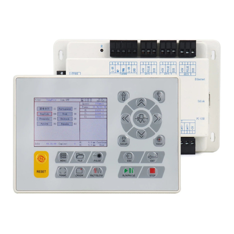
RuiDa RDC6442G-DFM-RD User manual

User’s Manual of RDC6442G(U)-DFM-RD Control System
SHENZHEN RUIDA TECHNOLOGY
RDC6442G(U)
-DFM-RD
Control System Manual
Read this manual before operation
The content include of electric connections and operating steps
Read the manual to operate the systems
RuiDa Technology Co., Ltd
Addr: 202-203,B-Block,Technology Building,NO.,1057 Nanhai
Avenue,Nanshan District,Shenzhen city,Guangdong
Province,P.R.China
Tel: 0755--26066687
Fax: 0755--26982287
E-mail: sale[email protected]m
Web: www.rd-acs.com

User’s Manual of RDC6442G(U)-DFM-RD Control System
SHENZHEN RUIDA TECHNOLOGY
COPYRIGHT
All rights reserved.You may not reproduce, transmit, store in
a retrieval system or adapt thispublication, in any form or by any
means, without the prior written permissionof RuiDa, except as
allowed under applicable copyright laws. We have
identifiedwords that we consider as trademarks. Neither the
presence or absence oftrademark identifications affects the legal
status of any trademarks.

User’s Manual of RDC6442G(U)-DFM-RD Control System
SHENZHEN RUIDA TECHNOLOGY
CERTIFICATION
DECLARATION
CE
The product has been certified by the CE (Commutate European) safety certification.
It has passed the corresponding conformity assessment procedure and the
manufacturer's declaration of conformity, in accordance with the relevant EU directive.
ROHS
This product has been certified by EU legislation (Restriction of Hazardous Substances)
Safety certification; comply with relevant EU environmental regulations.
FCC
This product has been certified by the Federal Communications Commission for safety,
Comply with us electronic safety regulations.

User’s Manual of RDC6442G(U)-DFM-RD Control System
SHENZHEN RUIDA TECHNOLOGY
SAFETY INFORMATION
When using this system, please make sure the operation is correct and the usage is safe.
Some signs or text will be used to remind you to pay attention to the dangerous matters
and some important information.
Dangerous:
Indicates a serious danger. In the process of use, if the operation is
improper or the way of use is wrong, it may cause serious injury or
even death to the user. Please do not operate it easily until you have
made sure that the operation method is correct and the way of use is
correct.
Warning:
Danger.n the process of use, if the operation is improper or the use
is wrong, which may lead to the injury of the personnel, please do
not operate the personnel and related personnel easily, until ensure
the correct operation method and use method is correct before use.
Cautious:
Represents the potential risk of the product. In the process of use, if
the use method is wrong or improper operation, it may cause
damage to the product or some parts. Please do not use it until you
have made sure that the operation method is correct and the usage is
correct.
Important:
Represents important information to be paid attention to during the
use of the product.Please do not ignore this information, this
information will provide effective operational help.
This sign indicates laser radiation, which is usually posted on products
with laser output. Please be careful with laser and pay attention to
safety when using this kind of equipment.

User’s Manual of RDC6442G(U)-DFM-RD Control System
SHENZHEN RUIDA TECHNOLOGY
Sign in、Devanning、Examine cargo
The product itself with plastic or metal shell, can protect the external electrical
components from damage. The products are packed in foam bags and anti-static bags. If
there is any external damage to the package, check the equipment and notify the carrier
and carrier in writing of the damage.
Inportant:
After receiving the product, please check whether the outer package is
intact, check whether the product is complete after unpacking and
whether all parts are intact. If any damage is found, please contact ruida
immediately.
Remove all cargo from package and keep packing material and wiring parts. Please take
care of the safety of the goods when unpacking them.After taking out the goods, please
check whether the parts are complete and intact. If any missing parts or damaged parts
are found, please contact ruida technology immediately.Do not install or debug the
equipment if any obvious damage is found.

User’s Manual of RDC6442G(U)-DFM-RD Control System
SHENZHEN RUIDA TECHNOLOGY
Contents
Section 1 Overview.......................................................................................................................................1
1.1 Briefing............................................................................................................................................... 1
1.2 Description of Controller Model........................................................................................................ 1
1.3 Comparison of Controller Performance.............................................................................................1
Section 2 Installation Size............................................................................................................................ 2
2.1 Installation Size of MainBoard........................................................................................................... 4
2.2 Size of Panel........................................................................................................................................5
Section 3 Object Pictures and Interfaces.....................................................................................................6
3.1 Object Pictures of MainBoard............................................................................................................7
3.2 Object Pictures of Panel.....................................................................................................................8
3.3 Electric connection.............................................................................................................................9
3.4 Lamp instruction................................................................................................................................ 9
Section 4 Description of Interface Signal for MainBoard..........................................................................10
4.1 Interface of Main Power Source CN0...............................................................................................11
4.2 Panel Signal-Cable Interface HMI.....................................................................................................11
4.3 Udisk interface................................................................................................................................. 11
4.4 PC-USB interface.............................................................................................................................. 11
4.5 Ethernet Interface............................................................................................................................ 12
4.6 General Output Port CN1.................................................................................................................13
4.7 General Input Port CN2....................................................................................................................13
4.8 4-axle Spacing Input Interface CN3/CN4......................................................................................... 14
4.9 X/Y/Z/U axle Motor Driver Interface AXIS_X~AXIS_U..................................................................... 15
4.10 Laser Power Control Interface CN5/CN6....................................................................................... 15
Section 5 Examples of Laser Power Interface............................................................................................16
5.1 Brief.................................................................................................................................................. 17
5.2 Examples of Glass tube Laser Power............................................................................................... 18
5.3 Examples of RF-Laser....................................................................................................................... 19
Section 6 Example of Driver Interface for Step-servo Motor....................................................................20
6.1 Brief.................................................................................................................................................. 21
6.2 Examples of Motor Driver Connection............................................................................................ 22
Section 7 Examples of IO-port Wiring........................................................................................................23
7.1 Input................................................................................................................................................. 24
7.2 Output.............................................................................................................................................. 25
Section 8 Operating Instruction of Panel...................................................................................................26
8.1 Introduction to the Panel and Keys..................................................................................................27
8.1.1 The whole panel........................................................................................................................28
8.1.2 Introduction to the Keys........................................................................................................... 29
8.2 Introduction to the Main Interface..................................................................................................30
8.2.1 The whole panel........................................................................................................................28
8.2.2 Introduction to the Keys........................................................................................................... 29

User’s Manual of RDC6442G(U)-DFM-RD Control System
SHENZHEN RUIDA TECHNOLOGY
8.2.3 Max/Min power keys................................................................................................................ 28
8.2.4 Set the layer parameters...........................................................................................................29
8.3 Z/U Key............................................................................................................................................. 31
8.3.1 Z move.......................................................................................................................................28
8.3.2 U move...................................................................................................................................... 29
8.3.3 Axis reset+................................................................................................................................. 28
8.3.4 Manual set+...............................................................................................................................29
8.3.5 Laser set+.................................................................................................................................. 28
8.3.6 Origin set+................................................................................................................................. 29
8.3.7 Set Fact Para..............................................................................................................................28
8.3.8 Def Fact Para............................................................................................................................. 29
8.3.9 Auto Focus.................................................................................................................................28
8.3.10 Language................................................................................................................................. 29
8.3.11 IP Setup................................................................................................................................... 28
8.3.12 Diagnoses................................................................................................................................ 29
8.3.13 Screen Origin...........................................................................................................................29
8.4 File Key............................................................................................................................................. 31
8.4.1 Memory File.............................................................................................................................. 28
8.4.2 U Disk File..................................................................................................................................29
8.5 Introduction to some alarm info......................................................................................................32
Section 9 Manufacturer/User Parameters Explanation............................................................................ 26
9.1 Manufacturer parameters................................................................................................................27
9.2 User parameters...............................................................................................................................53

User’
s Manual of RDC6442G(U)-DFM-RD Control System
SHENZHEN RUIDA TECHNOLOGY
1
Section 1 Overview
CONTENTS:
Briefing
Description of Controller Model
Comparison of Controller Performance

User’
s Manual of RDC6442G(U)-DFM-RD Control System
SHENZHEN RUIDA TECHNOLOGY
2
1.1Briefing
RDC644XG system is a new generation system for control of laser engraving and cutting,
which is developed by RD Co., Ltd. In addition to high hardware stability, high voltage or
static electricity rejection, and friendly 3.5’’ TFT man-machine display. This system is
provided with stronger software function including perfect 4-axle motion control function,
large-capacity file storage, two-channel adjustable digits laser power control interface,
USB driver of stronger compatibility, multi-channel general/special IO control, and, this
system can communicate with PC by USB2.0 or Ethernet, and the communication mode
is automatically checked by the system.
1.2 Description of Controller Model
1.3 Comparison of Controller Performance
RDLC
420
RDC6332G
RDC6342G
RDC644XG
Power
Feature
One-way
5V, one-way
24V,
independent
Only one-way
24V (compatible with
36V for power
supply, but not
recommended)
Only one-way
24V (compatible with
36V for power supply,
but not
recommended)
Only one-way 24V
(compatible with 36V for
power supply, but not
recommended)
Laser
Port
Feature
One-way
digit and
one-way
analog
Two-way digits
and two-way analog
port, settable
independently and
non-interacted
Two-way digits
and two-way analog
port, settable
independently and
non-interacted
Two-way digits port,
settable independently
and non-interacted
USB
Feature
Copying
Speed
Common
Quick
Quick
Very Quick
Compatib
ility
Support
USB disks with
Support all USB
disks with different
Support all USB
disks with different
Support all USB

User’
s Manual of RDC6442G(U)-DFM-RD Control System
SHENZHEN RUIDA TECHNOLOGY
3
small capacity
capacities
capacities
disks with different
capacities
Memor
y Feature
Capacity
64M
256M
256M
128M
Fault
Tolerance
Common
Capable of
checking defective
track and formatting
and good in fault
tolerance
Capable of
checking defective
track and formatting
and good in fault
tolerance
Capable of
checking defective track
and formatting and good
in fault tolerance
Genera
l IO Feature
Input Port
Two ways
4 ways (two for
general, two for
specialties)
4 ways (two for
general, two for
specialties)
4 ways (two for
general, two for
specialties)
Output
Port
1-way
(low current,
so additional
drive is
needed)
4-ways (500mA
high current for each,
OC output, no
reverse current
protection)
4-ways (500mA
high current for each,
OC output, no
reverse current
protection)
4-ways (500mA
high current for each,
OC output, reverse
current protection
included)
Softwa
re Feature
Power-off
restart for
Engraving
YES
YES
YES
YES
Multi-origi
n Logics
NO
YES
YES
YES
Paramete
r Backup
Logics
NO
YES
YES
YES
Work time
Preview
NO
YES (the work
time accurate to
1ms)
YES (the work
time accurate to
1ms)
YES (the work time
accurate to 1ms)
Online
Update
Mainboard
Program
NO
YES
YES
YES
Displa
y
Featur
e
Online
Modification
Laser
Power/Speed
YES
YES
YES
YES
Offline
Modification
Layer
parameters
NO
YES
YES
YES
Online
Update
Startup
Display
NO
YES
YES
NO
File
dynamic/static
preview
NO
YES
YES
YES
Run
progress bar
display
NO
NO
NO
YES
Modificati
on
Factory/User’s
NO
YES
YES
NO

User’
s Manual of RDC6442G(U)-DFM-RD Control System
SHENZHEN RUIDA TECHNOLOGY
4
para on
display
Display
type
128*64,
dot display
320*240 TFT
display
320*240 TFT
display
320*480 TFT
display
Motion
-axle
Feature
Soft
Spacing
YES
YES
YES
YES
Hard
Spacing
NO
YES
YES
YES
Z-axle
Linkage
NO
YES
YES
YES
Feeding
Feature
Single
direction
Single/double
direction for option
Single/double
direction for option
Single/double
direction for option
Power-on
Resetting
Fixed
Configurable for
each axes
Configurable for
each axes
Configurable for
each axes
Key
Speed
Fixed
Configurable
Configurable
Configurable
Axles
4
3 (Z axes is
configurable to flat or
feedin axes
)
3 (Z axes is
configurable to flat or
feedin axes
)
4
Encryp
tion
Feature
Encryption
based on the
PC time
Realtime clock
and battery
integrated for
hardware encryption
Realtime clock
and battery
integrated for
hardware encryption
No realtime clock,
but encryption included
Comm
unicate
Mode
USB2.0
10/100MHZ
Ethernet or USB2.0
10/100MHZ
Ethernet or USB2.0
10/100MHZ
Ethernet or USB2.0,
communication mode is
automatically checked

User’
s Manual of RDC6442G(U)-DFM-RD Control System
SHENZHEN RUIDA TECHNOLOGY
5
Section 2 Installation
Size
CONTENTS:
Installation Size of MainBoard
Size of Panel

User’
s Manual of RDC6442G(U)-DFM-RD Control System
SHENZHEN RUIDA TECHNOLOGY
6
2.1 Installation Size of MainBoard
The unit of all sizes is millimeter (mm) and the size accurate to 0.1mm (the four holes are
symmetrical)
Figure

User’
s Manual of RDC6442G(U)-DFM-RD Control System
SHENZHEN RUIDA TECHNOLOGY
7
2.2 Size of Panel
The unit of all sizes is millimeter (mm) and the size accurate to 0.1mm.
Figure

User’
s Manual of RDC6442G(U)-DFM-RD Control System
SHENZHEN RUIDA TECHNOLOGY
8
Section3 Object
Pictures and Interfaces
CONTENTS:
Object Pictures of MainBoard
Object Pictures of Panel
Electric connection
Lamp instruction

User’
s Manual of RDC6442G(U)-DFM-RD Control System
SHENZHEN RUIDA TECHNOLOGY
9
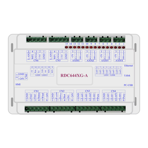
3.1 Object Pictures of MainBoard
For more detailed pin description, see the Chapter 4: Description of Interface Signal for
MainBoard.
Figure: 3.1-1 Object Picture of
MainBoard

User’
s Manual of RDC6442G(U)-DFM-RD Control System
SHENZHEN RUIDA TECHNOLOGY
10
3.2 Object Pictures of Panel
Figure: 3.2-1 Object Picture of Panel

User’
s Manual of RDC6442G(U)-DFM-RD Control System
SHENZHEN RUIDA TECHNOLOGY
11
3.3 Electric connection
3.4 Lamp instruction
RDC6442G have fifteen red lamps:
LED NUMBER
NAME
SENSE
LED1
LmtX-
Xnegative limit indicator
LED2
LmtX+
Xpositive limit
LED3
LmtY-
Ynegative limit
LED4
LmtY+
Ypositive limit
LED5
LmtZ-
Znegative limit
LED6
LmtZ+
Zpositive limit
LED7
LmtU-
Unegative limit
Figure 3.3-1 electric
connection

User’
s Manual of RDC6442G(U)-DFM-RD Control System
SHENZHEN RUIDA TECHNOLOGY
12
LED8
LmtU+
Upositive limit
LED9
Wp1
Indication for water
protect 1
LED10
Wp2
Indication for water
protect 2
LED11
Act
Ethernet communication
LED12
Link
Ethernet connection
LED13
Err
error in controller
hardware
LED14
Run
the normal running status
LED15
+5V
+5V power supply

User’
s Manual of RDC6442G(U)-DFM-RD Control System
SHENZHEN RUIDA TECHNOLOGY
13
Section 4 Description
of Interface Signal for
MainBoard
CONTENTS:
Interface of Main Power Source CN0
Panel Signal-Cable Interface HMI
Udisk Interface
PC-USB Interface
Ethernet Interface
General Output Port CN1
General Input Port CN2
4-axle Spacing Input Interface CN3/CN4
X/Y/Z/U axle Motor Driver Interface AXIS_X~AXIS_U
Laser Power Control Interface CN5/CN6
This manual suits for next models
1
Table of contents
Other RuiDa Control System manuals
Popular Control System manuals by other brands

LTI MOTION
LTI MOTION MotionOne CM Programming manual

Extron electronics
Extron electronics TouchLink TLP Pro 525C Series user guide

BriskHeat
BriskHeat XtremeFLEX MSTAT Series instruction manual

Lehigh
Lehigh SOLITAIRE WBX-4 manual

HEIDENHAIN
HEIDENHAIN ECN 413 2C Mounting instructions

Norac
Norac UC4+ installation manual