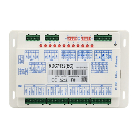
RuiDa KT332N User manual

KT332N Cutting &engraving control system user manual V1.1
KT332N
Laser cutting&engraving control system user manual
Users should read this manual before using the controller.
This manual contents is the system operation manual
Read this manual carefully to ensure proper electrical
connection

KT332N Cutting &engraving control system user manual V1.1
NOTICE
We reserves the right to modify the products and product
specifications in this manual without prior notice, and reserves the
right to modify any documents attached to this product.
Users should read this manual carefully when using the products
described in this article. We are not responsible for direct, indirect,
special, incidental or corresponding losses or liabilities caused by the
use of this manual or this product incorrect.We do not assume the
following direct or indirect liabilities or losses:
Users use this manual or this product improperly
Loss caused by users failing to follow relevant safety
operation procedures
The loss caused by natural forces makes the machine in dangerous.
The user is responsible for designing effective error handling and
safety protection mechanisms in the machine. Our Intelligence has
no obligation or responsibility for the incidental or corresponding
damage caused.

KT332N Cutting &engraving control system user manual V1.1
CERTIFICATION STATEMENT
CE Certification statement
This product has passed the European Union CE (Communate Europpene) safety
certification, has passed the corresponding conformity assessment procedures and
the manufacturer's declaration of conformity, and complies with the relevant EU
directives.
ROHS Certification statement
This product has passed the "Restriction of Hazardous Substances" safety
certification established by EU legislation and complies with relevant EU
environmental protection regulations.
FCC Certification statement
This product has passed the Federal Communications Commission safety
certification and complies with relevant US electronic product safety regulations.

KT332N Cutting &engraving control system user manual V1.1
SAFETY INFORMATION
Please make sure that the operation is correct and the method is safe when using
the system. Some signs or words will be used to remind you of dangerous matters
and some important information.
Danger:
It indicates a serious danger. In the process of using, if improper
operation or wrong usage method may cause serious injury or even
death to the personnel, please do not use it easily until the operation
method is correct and the usage method is correct.
Warning:
It indicates a serious danger. In the process of using, if improper
operation or wrong usage method may cause injury to the personnel,
please do not operate it until the operation method is correct and the
usage method is correct.
Cautious:
It indicates potential product risk. In the process of using, if the use
method is incorrect or the operation is improper, it may cause
damage to the product or some parts. Please do not use it until it is
ensured that the operation method is correct and the use method is
correct.
Important:
It indicates important information that needs attention during the
use of the product. Please do not ignore this information, it will
provide effective operation assistance.
This mark indicates laser radiation, which is generally attached to
products that output laser. When using such equipment, please be
careful with laser and pay attention to safety.

KT332N Cutting &engraving control system user manual V1.1
Receiving, Unpacking, Inspection
The product has a plastic or metal casing to protect the exterior electrical component
from damage. The product is wrapped in a foam bag and packed in an antistatic bag.
If the package has any external damage, please check the goods and notify the
carrier of the damage situation in writing.
Important:
After receiving the products, please check whether the outer
packaging is in good condition, whether the product is complete
after unpacking, and whether the parts are in good condition. If you
find damage, please contact with us immediately.
Keep the packaging materials and wiring accessories when unpacking. Please be
careful when disassembling the package. After unpacking the goods, please check if
the parts are complete. If you find that the parts are missing or the parts are
damaged, please contact with us immediately. If you notice any obvious damage to
the device, do not install the device or commission the device.
KT332N cutting system delivery list is shown in the following: (As the product is
constantly updated, the accessories that may be received are difference)
Component
Quantity
Description
KT332N(EC)
1
Version number
V23.01.XX
KTPA001
1
KTPA001 connectors
1
USB cable(2.0 double magnetic ring -3M)
black
1
Connecting the machine
case to the PC (USB
communication)
USB Adapter cable AM/AF(with single
magnetic ring-1M)
1
Connecting the machine
case to the controller U
disk interface
USB Adapter cable(with single magnetic
ring -1M)Black
1
Connecting the machine
case and the controller
USB communication
interface
6445- Five-core cable 1.5M
1
Standard wiring length is
1.5M
User manual
1
Download from website

KT332N Cutting &engraving control system user manual V1.1
Contents
Chapter 1 Overview..................................................................................................................................... 1
1.1 KT332N introduction............................................................................................................................. 2
Chapter 2 Controller dimension.............................................................................................................. 3
2.1 Dimension of controller.........................................................................................................................4
2.2 Dimension of pannel............................................................................................................................. 4
Chapter 3 Overview of the product........................................................................................................... 6
3.1 Controller overview...............................................................................................................................7
3.2 Panel Overview......................................................................................................................................7
3.3 Control system electrical connection diagram..................................................................................8
Chapter 4 Controller specification............................................................................................................. 9
4.1 Main power interface POWER............................................................................................................ 9
4.2 Controller and display board connector HMI..................................................................................10
4.3 Udisk interface..................................................................................................................................... 10
4.4 PC-USB interface................................................................................................................................10
4.5 General / dedicated output................................................................................................................ 10
4.6 Dedicated / general input interface INPUT..................................................................................... 11
4.7 Three-axis limit input interface LIMIT...............................................................................................11
4.8 X/Y/U Three-axis driver interface AXIS_X~AXIS_U..................................................................... 12
4.9 Laser power control interface LASER............................................................................................. 12
Chapter 5 Example of laser power interface.........................................................................................14
5.1 Overview............................................................................................................................................... 15
5.2 Glass tube laser power wiring diagram........................................................................................... 15
5.3 RF CO2 laser wiring diagram............................................................................................................15
Chapter 6 Example of stepper motor driver interface..........................................................................17
6.1 Overview............................................................................................................................................... 18
6.2 Drive wiring diagrams......................................................................................................................... 19
Chapter 7 IO port wiring example ......................................................................................................... 20
7.1 Input.......................................................................................................................................................21
7.2 Output....................................................................................................................................................22
Chapter 8 HMI operation instructions.....................................................................................................23
8.1 Introduction...........................................................................................................................................24
8.1.1 Overview............................................................................................................................................24
8.1.2 Key function description..................................................................................................................25
8.2 Main interface functions..................................................................................................................... 26
8.3 Speed setting....................................................................................................................................... 27
8.4 Power setting....................................................................................................................................... 27
8.5 Layer function...................................................................................................................................... 28
8.6 Menu function..................................................................................................................................... 29
8.6.1 Parameter settings...........................................................................................................................30
8.6.2 Motion parameter.............................................................................................................................30

KT332N Cutting &engraving control system user manual V1.1
8.6.3 Frame setting....................................................................................................................................30
8.6.4 Blow Setting...................................................................................................................................... 30
8.6.5 Speed setting....................................................................................................................................34
8.6.6 Machine configuration.....................................................................................................................30
8.6.7 Rotate function settings.................................................................................................................. 30
8.6.8 Jog settings.......................................................................................................................................30
8.6.9 Pulse setting..................................................................................................................................... 30
8.6.10 Axis reset........................................................................................................................................ 34
8.6.11 Multiple points positioning setting...............................................................................................35
8.6.12 Screen origin setting..................................................................................................................... 35
8.6.13 Keypad Lock Settings................................................................................................................... 36
8.6.14 Language settings......................................................................................................................... 37
8.6.15 Diagnosis........................................................................................................................................ 40
8.6.16 System Information....................................................................................................................... 41
8.6.17 Back up factory parameters.........................................................................................................39
8.6.18 Restore factory parameters......................................................................................................... 40
8.6.19 Controller management................................................................................................................ 41
8.6.20 Time setting.................................................................................................................................... 41
8.6.21 Authorization Management..........................................................................................................41
8.7 File management.................................................................................................................................43
8.7.1 Memory file........................................................................................................................................43
8.7.2 File parameters................................................................................................................................ 44
8.7.3 Array Information............................................................................................................................. 46
8.7.4 Auto feeding parameters .............................................................................................................. 47
8.7.5 Memory operation............................................................................................................................46
8.7.6 U disk file .........................................................................................................................................47
8.8 Password input and setting............................................................................................................... 48
8.8.1 Password entry.................................................................................................................................48
8.8.2 Password setting..............................................................................................................................48
8.9 Tips and alarms................................................................................................................................... 49
8.10 Parameter setting operation............................................................................................................49
8.10.1 Option parameter box................................................................................................................... 50
8.10.2 Numeric parameter box................................................................................................................ 50
Chapter 9 Detailed manufacturer / user parameters........................................................................... 52
9.1 Vendor parameters............................................................................................................................. 53
9.2 User parameters..................................................................................................................................56

KT332N Cutting &engraving control system user manual V1.1
1
Chapter 1 Introduction
MAIN CONTENTS OF THIS CHAPTER:
KT332N Introduction

KT332N Cutting &engraving control system user manual V1.1
2
1.1 KT332N Introduction to Control System
KT332N control system is the latest generation of standalone laser engraving and cutting control
system developed by our company. This control system has better stability and anti-interference
performance. HMI is based on the 3.5-inch TFT screen which has more friendly operation
interface and powerful functions. 128M flash memory on board and an independent laser power
control port on board. General and dedicated output and input are integrated on board.
Communication support USB2.0.
This system has 2 panel with different color and can be

KT332N Cutting &engraving control system user manual V1.1
3
Chapter 2 Controller dimension
MAIN CONTENTS OF THIS CHAPTER:
Dimension of controller
Dimension of Panel

KT332N Cutting &engraving control system user manual V1.1
4
2.1 Dimension of controller
All dimensions are in mm, accurate to 0.1mm (four of the positioning holes are symmetrical)
2.2 Dimension of panel
All dimensions are in mm, accurate to 0.1mm

KT332N Cutting &engraving control system user manual V1.1
5

KT332N Cutting &engraving control system user manual V1.1
6
Chapter 3 Overview of the product
MAIN CONTENTS OF THIS CHAPTER:
Controller overview
Panel overview
Electrical connection diagram

KT332N Cutting &engraving control system user manual V1.1
7
3.1 Controller overview
For more detailed pin description, see Chapter 4 Interface Signal Description
3.2 Panel overview
3.1-1 controller
3.2-1 panel

KT332N Cutting &engraving control system user manual V1.1
8
3.3 Electrical connection diagram of control system
3.3-1 Electrical connection diagram of control system

KT332N Cutting &engraving control system user manual V1.1
9
Chapter 4 Controller specification
MAIN CONTENTS OF THIS CHAPTER:
Main power interface POWER
Controller and panel interface HMI
U-disk interface
PC-USB interface
General and dedicated OUTPUT
General and dedicated INPUT
Limit input interface LIMIT
X, Y, U axes interface
Definition of X, Y,U axis
Laser power interface LASER
4.1 Main power supply interface POWER
NO.
Signal
Definition
1
GND
24V Power ground(input)

KT332N Cutting &engraving control system user manual V1.1
10
4.2 Controller and panel interface
The cable that connects the controller and the panel is supplied as an accessory to customer.
Please connect the controller and the panel correctly with this cable.
4.3 U-disk Port
There is a USB port named U-disk on the controller. It is compatible with U stick and can read
and write the U stick.
4.4 PC-USB interface
PC-USB is a communication port that can build up the communication between the controller
and the computer. It supports USB2.0 protocol.
4.5 Ethernet port
KT332N has the Ethernet port and USB port. KT332G only have USB port.
4.6 General and dedicated output
General and dedicated output definition
PIN
Signal
Definition
1
+24V
Power supply. Which can supply power to other devices
2
Aux.Air
Dedicated output. When auxiliary air control is enabled, this
port outputs a control signal to control the valve or other
relay to release auxiliary air. This port is multiplexed with
pen control signal. When auxiliary air control is disabled, this
port is assigned as pen control.
The output type is open collector.
The output can be set to be synchronized with laser or
synchronized with work.
3
Status
Dedicated output, working status signal port (or the second
pen signal). This port is multiplexed with second pen control
signal. When auxiliary air control is disabled, this port is
2
+24V
24V (input)
Caution
This control system uses a single 24V power supply. In order to leave a
certain margin, it is recommended to choose a power supply of 24V / 2A
or more. At the same time, the control system is compatible with 36V
power supply, that is, the driver's 36V power can be directly connected to
the main power interface of the control system, but this is not
recommended

KT332N Cutting &engraving control system user manual V1.1
11
assigned as second pen control. the multiplexing function is
also enabled by auxiliary air control is enabled or not.
Output is an open collector type. When working, this output
connect to GND.
4
Out1
General output, reserved.
5
Out2
General output, reserved.
6
GND
Signal Gnd
Prompt
All output signals are isolated by opto-couplers. OC output, the
maximum driving capacity is 300mA, which can directly drive 6V / 24V
relay.
4.6 General/ dedicated input interface INPUT
PIN
SIGNAL
Definition
1
GND
Power ground (output)
2
IN1
General input, reserved
3
IN2
General input, for a remote laser shot control. When
connected to GND, it can perform laser pulse.
4
IntLock
Dedicated input, protection signal input. If the machine needs
to be protected in a specific state (such as cover open), the
alarm signal is input to this port. This port can be enabled
and disabled. When this port is disabled, this signal is
neglected by the controller. If this port is enabled, the
machine is protected when the input is in high voltage or the
port is float. Once the alarm triggered, motion will be stopped
and the laser is switched off synchronously.
5
Ex-Run
Dedicated input. Extern start input. Usually for foot control
switch start the machine. Low level is valid.
When system is idle, if a low level signal is sent to this port,
machine will be start. If the machine is working, a low level
signal is sent to this port, machine will be stopped. Send
again, machine will go on working.
6
+24V
Power supply + 24V (output)
4.7 Limit input
X/Y axis limit interface CN4
PIN
SIGNAL
Definition
1
+5V
Power ground (output)
2
LmtU+
U+,U axis moves to the limit at the maximum coordinate

KT332N Cutting &engraving control system user manual V1.1
12
3
LmtU-
U-,U axis moves to the limit at 0 coordinate
4
LmtY-
Y-,Y axis moves to the limit at 0 coordinate
5
LmtX-
X-,X axis moves to the limit at 0 coordinate
6
GND
Power + 5V (output)
On the controller, only one limit switch is needed. The limit is installed on the negative direction of
the axis. The protection of motion is by the soft limit.
The polarity can be set according to the limit switch type, such as PNP or NPN. And there is a led
indicator on the controller can show the limit is triggered or not.
This port is compatible with 5V, 12V or 24V.
4.8 X, Y, U axis interface AXIS_X, AXIS_Y, AXIS_U
The four motion axis interfaces are the same, taking the X axis interface AXIS_X as an example:
PIN
SIGNAL
Definition
1
DIR
Direction signal terminal (TTL)
2
PUL
Pulse signal terminal (TTL)
3
+5V
5V power supply (output, only for driver common
positive connection)
Prompt
The pulse signal and direction signal are both OC output, so the
controller and motor driver must use the common anode connection
method. Common cathode and differential connection methods are not
supported.
4.9 Laser power control interface LASER
PIN
SINGAL
Definition
1
GND
Laser power ground (output)
2
L-ON
Laser emission control.
3
LPWM
Laser machine/laser tube power control interface
1. If it is the RF laser, this pin is connected to the laser
RF-PWM to control laser power.
2.If it is the glass tube,this pin is connected to the PWM of
laser power to control laser power.
4
WP
It is the first laser power supply water protection status input
port. When water protection 1 is enabled, the controller will
detect the water protection 1 input port, if the port is in low
voltage, it is normal. If it is in high voltage, the controller will
forcibly turn off the laser, and the processing work will Pause
and the system will alarm. If the water protection 1 is not
enabled, the controller does not detect the water protection 1
input port. The user doesn’t need to connect the water

KT332N Cutting &engraving control system user manual V1.1
13
protection 1.
Water protection input must use 24V voltage input
5
L-AN
Laser power analog signal output. For glass tube laser power
supply, it is recommended to use this pin for power signal.
Prompt
Please select the correct laser type in the factory parameter settings.
When a glass laser tube is used, and the control signal cable is very long
from the controller to the laser power, if L-AN is for the power control, the
long cable will cause interference and make the laser power unstable. So
for this situation, PWM signal can replace the L-AN to control the glass
tube’s power. And decrease the interference.
Table of contents
Other RuiDa Control System manuals
Popular Control System manuals by other brands

sauter
sauter eValveco UVC106MF015 Fitting instructions

ICM Controls
ICM Controls ICM2813 Installation, operation & application guide

Interroll
Interroll ZoneControl operating manual

Steril-Aire
Steril-Aire 8100PVAB Installation and operation manual

Franke
Franke DVS SH07-002 Installation & operating instructions

rotork
rotork p3 Technical manual