Ruskin MiniCORE MCV-500 User manual

1
INSTALLATION INSTRUCTIONS
MC500-1ERV
JANUARY 10, 2018
SUPERSEDES: NONE
INSTALLATION INSTRUCTIONS FOR MINICORE VENTILATOR (MCV) WITH FACTORY
INSTALLED OPTIONS USED AS A STAND ALONE OR WITH SPLIT SYSTEMS UNITS
ENERGY RECOVERY CORE
Energy recovery COMPONENT certied
to the AHRI Air-to-Air Energy Recovery
Ventilation Equipment Certication
Program in accordance with AHRI Standard
1060-2000. Actual performance in packaged
equipment may vary.
MiniCOREVentilator
ETL Certied
per UL 1995 and
CSA 22.2
I - Shipping And Packing List
Package 1 of 1 contains:
1 - MiniCore Ventilator Assembly
II - Shipping Damage
Check unit for shipping damage. Receiving party should
contact last carrier immediately if shipping damage is
found.
III - General
These instructions are intended as a general guide and
do not supersede local codes in any way. Authorities
having jurisdiction should be consulted before installation.
IV - Requirements
When installed, the unit must be electrically wired and
grounded in accordance with local codes or, in the
absence of local codes, with the current National Electric
Code, ANSI/NFPA No. 70.
V - Application
MiniCore ventilators are used as a stand alone indoor
option for heat recovery ventilators used in light
commercial applications. These ventilators conserve
energy by transferring heat energy across two opposing
air streams using a polymer core heat exchanger. This
process works in the summer by rejecting the heat energy
from incoming intake air and in the winter by conserving
the heat energy from the exhaust air, allowing outdoor
ventilation rates to be increased by factors of three or
more without additional energy penalty or increase in size
of the heating or air conditioning systems.
VI - Rigging Unit For Lifting
1. Maximum weight of unit is:
VII - Installation
When choosing a location to mount the MiniCore
Ventilator take into consideration ductwork layout as well
as access for future lter changes and Core cleaning. See
maintenance section on Page 4 for dimensions.
Model# MCV-500 MCV-1000
Net Weight 182 222
Ship Weight 230 270
2. Remove carton.
3. All panels must be in place for rigging.
4. Lift unit into place with a winch or jack.
WARNING
Electric shock hazard. Can cause injury or death.
Before attempting to perform any service or
maintenance, turn the electrical power to unit
OFF at disconnect switch(es). Unit may have
multiple power supplies.
CAUTION
Danger of sharp metallic edges. Can cause injury. Take care
when servicing unit to avoid accidental contact with sharp
edges.
Figure 1
Normal installation of the MiniCore Ventilator unit is
hanging from the 4 corners using the included hanging
kit though the units can be mounted on a shelf or on the
oor of a mechanical room using optional oor vibration
isolators.

2 MC500-1ERV
The maximum weight of a MiniCore Ventilator is less than
225 lbs, Using 3/8" all-thread and the included hanging
brackets is the preferable method of supporting the unit
though the use of metal strap to hang the unit is also
acceptable. When hanging the unit be sure to take into
account the need to provide access for lter replacement
and Core removal as well as blower balancing or removal
through the bottom access panels.
While orientation of the heat exchanging core inside of
the MiniCore Ventilator is important for maximizing airow
orientation of the Ventilator itself is not, the MiniCore can
be mounted in a vertical or horizontal fashion. Additionally
the Fresh Air intake and Return intake can either be
mounted on the side of the MiniCore or on the end by
switching the duct collar and cover panel attached using
5/16" screws. See Figure 2.
Figure 2
Duct Option 2
Duct Option 1
Once the MiniCore Ventilator is hung connect ductwork to
proper sectors of the unit with ¼" screws, use tape to seal
seams. Supply and Exhaust are labeled on the outside
of the cabinet and are determined by the orientation of
the Core inside of the MiniCore Ventilator, a sticker on
the Core will indicate the supply (outdoor air) vector.
The Outside Air and Return connections will always be
on the opposite side of the MiniCore Ventilator from their
respective Supply and Exhaust blowers. See Figure 2.
Wiring
A ¾" knock out is provided for high voltage on the top and
bottom of the high voltage disconnect switch mounted on
the side of the unit.
Figure 3
High voltage:
115V: Connect the high voltage wires to L1 (Hot) &
L2 (Common), hook the ground wire to the provided
grounding nut. See Wiring Diagrams on Pages 6-7.
208/230V: Single phase: Connect the high voltage wires
to L1 (Hot) & L2 (Common) connect the ground wire to
the provided ground nut. Check Voltage into the unit and
adjust the voltage input to the transformer from 230V to
208V if necessary by switching wires at transformer. See
Wiring Diagrams on Pages 6-7.
Low voltage:
Standard units: Pass low voltage wire through the
provided knockout on the 2 gang terminal strip access
box next to the power disconnect, and connect R to
terminal #1 of terminal block TB38 and G to terminal #3.
See Wiring Diagrams on Pages 6-7 and Figure 3
The MiniCore Ventilator can be controlled by any dry
contact closure like those in a CO2sensor with relay,
switch or timer.
ECM units: Pass the low voltage wiring through the
provide knockout on the terminal access box and connect
R to terminal #1 on 7 pin terminal box TB38 and G to #3.
The default wiring for the MiniCore Ventilator with ECMs
is to operate in the modulating speed mode terminals #4-7
are for speed control. To control both blowers in unison
wire the 0-10vdc control signal to terminals 4 (10vdc+)
and 5 (10vdc com) and add a jumper between terminals
4 and 6. If the Blowers are controlled independently then
wire the exhaust blower signal to terminals 4 &5 and the
supply signal to terminals 6 & 7, See Adjusting Blower
Speed in Section IX - System Check for balancing
information.
To use the motor in 2 speed operation attach the blue
wires from TB39 and TB40 to relays K163 & K164 at pin
#4. With the blue BL-25 and BL-30 wires in place the ECM
with default to 2 speed operation. See Wiring Diagram
on page 7 and Figure 4.

MC500-1ERV 3
VIII - Operation
How It Works
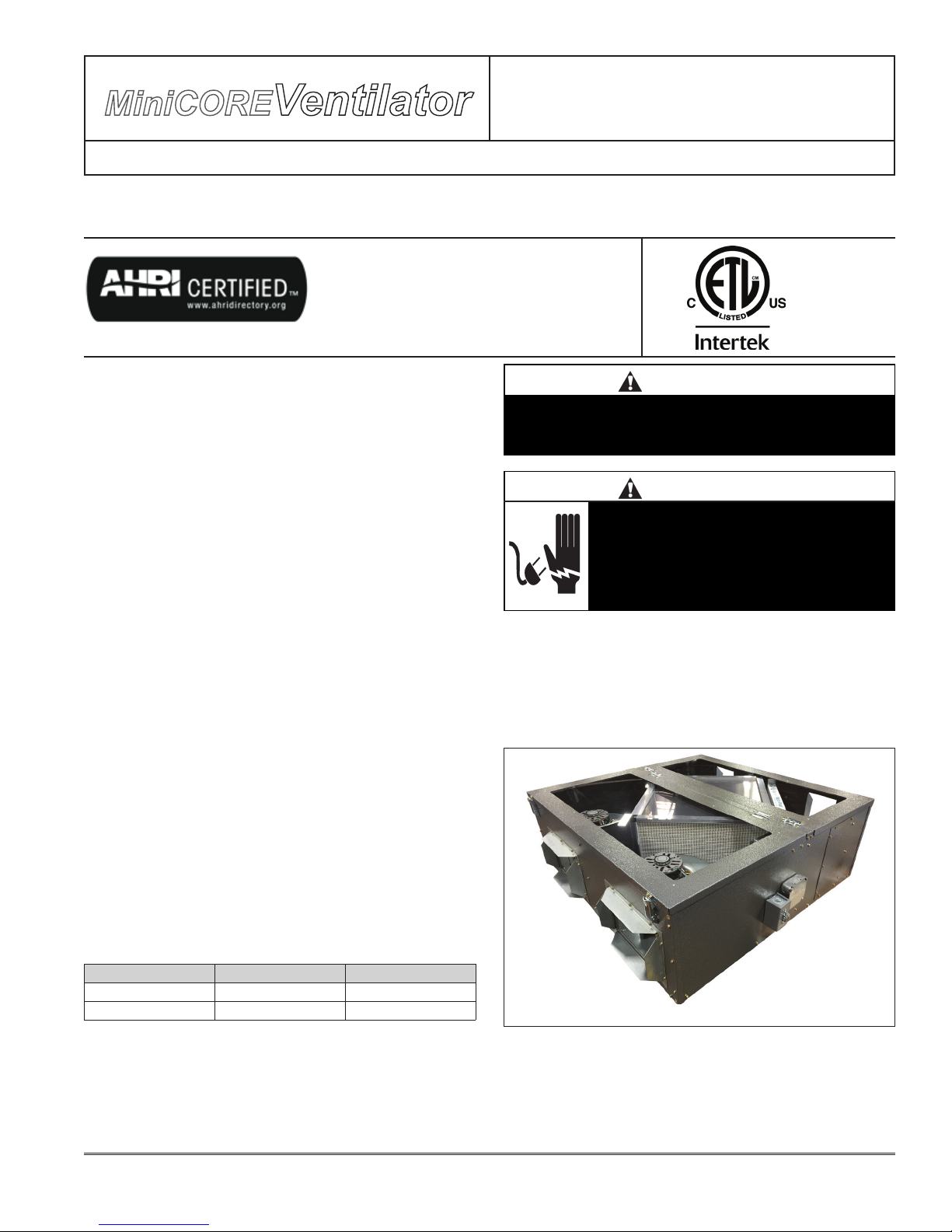
The unit uses a dPoint polymer based ERV core which
offers latent and sensible energy recovery with no cross
contamination and no moving parts. In the summer
outside heat and humidity is rejected from the incoming
outside airstream and exhausted out the building, while
in the winter the same process works to conserve wasted
heat and humidity making the building more efcient,
healthier and more comfortable.
The dense polymer membrane uses selective transfer
technology to allow heat and water vapor to permeate
through, while blocking contaminant compounds. The
transfer is driven by temperature and humidity differentials
between the airstreams. This allows you to reduce the
size of the cooling system by 30% while still meeting
outside air requirements.
The Cores material is designed to prevent mold and
bacteria growth – the material was ISO 846 tested with
a rating of 0 –, is designed to avoid virus transfer –ASTM
Method F-1671 tested with 0 penetration –, and eliminate
cross contamination from exhaust air – 0% EATR certied
to AHRI 1060. It’s polymer construction also means that it
is washable with water for easy cleaning.
IX - System Check
1. Turn off power to the unit
2. Remove access cover for the terminal strip access
box and add a jumper to terminals 1 & 3.
3. Restore power to the unit. Observe that both blower
motors are running.
4. Adjustments to the speed of the motors can be made
by changing the input on the multi tap blower motors,
the speed control on EC Motors or by adjusting the
optional speed control.
A - Blower Speed Adjustment
MCV500/1000 - Both fresh air and exhaust air blowers
are direct drive multi-tap motors. Both blowers are factory
set at "high" speed for maximum airow. To determine air
ow setting, external static pressure readings will need to
be read across the MiniCore.
Figure 4
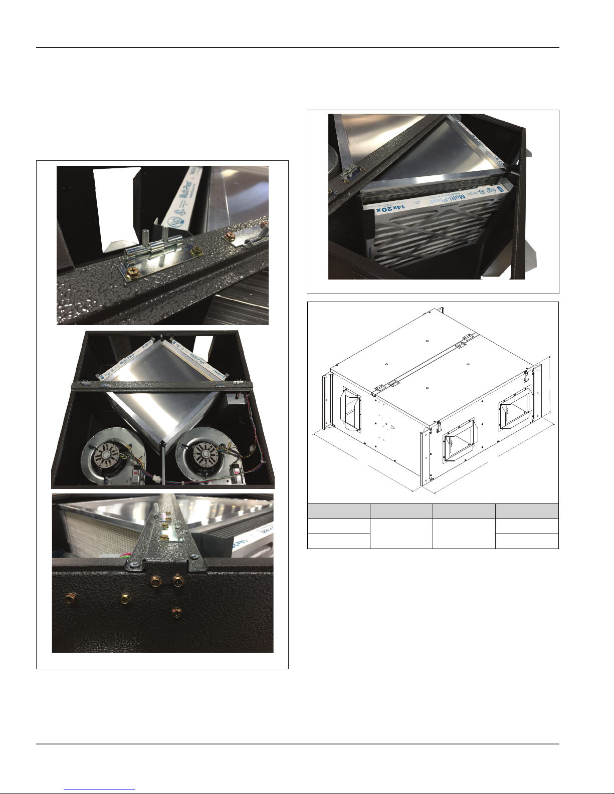
B - Air Balancing Adjustment
1. Remove plastic plugs in access panels (4 total).
2. With a manometer measure pressure drop [inches of
water column] diagonally across the MiniCore. Unit
CFM for 3 speed PMC motors is determined then by
referring to Table #1 on Page 5.
3. Repeat the same process for the other airow vector
of MiniCore.
4. System can be balanced by adding dampers to
ductwork or by adjusting blower speed.
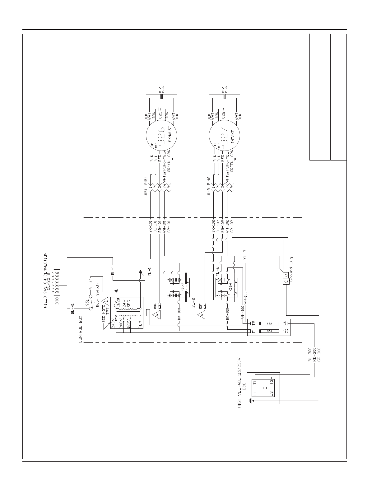
C - Adjusting Blower Speed
3 speed PCM motors: Standard units have 2 terminal
blocks available (TB39 for exhaust and TB40 for supply)
where the speed taps on the 3 speed motors can be
changed. Move the Black wire from terminal #1 to terminal
#2 (med) or #3 (low) to lower blower speeds. An additional
115 or 230 volt speed control is available (part #s?) to
balance each blower with in these ranges. The speed
control is wired in line on the Black BK-102 or BK-101
wires before the terminal block, and is mounted externally
in a 2 gang work box on or near the MiniCore. Speed is
reduced by turning the knob counter clockwise until cfm is
met. See Table #1 on Page 5 for balancing data..
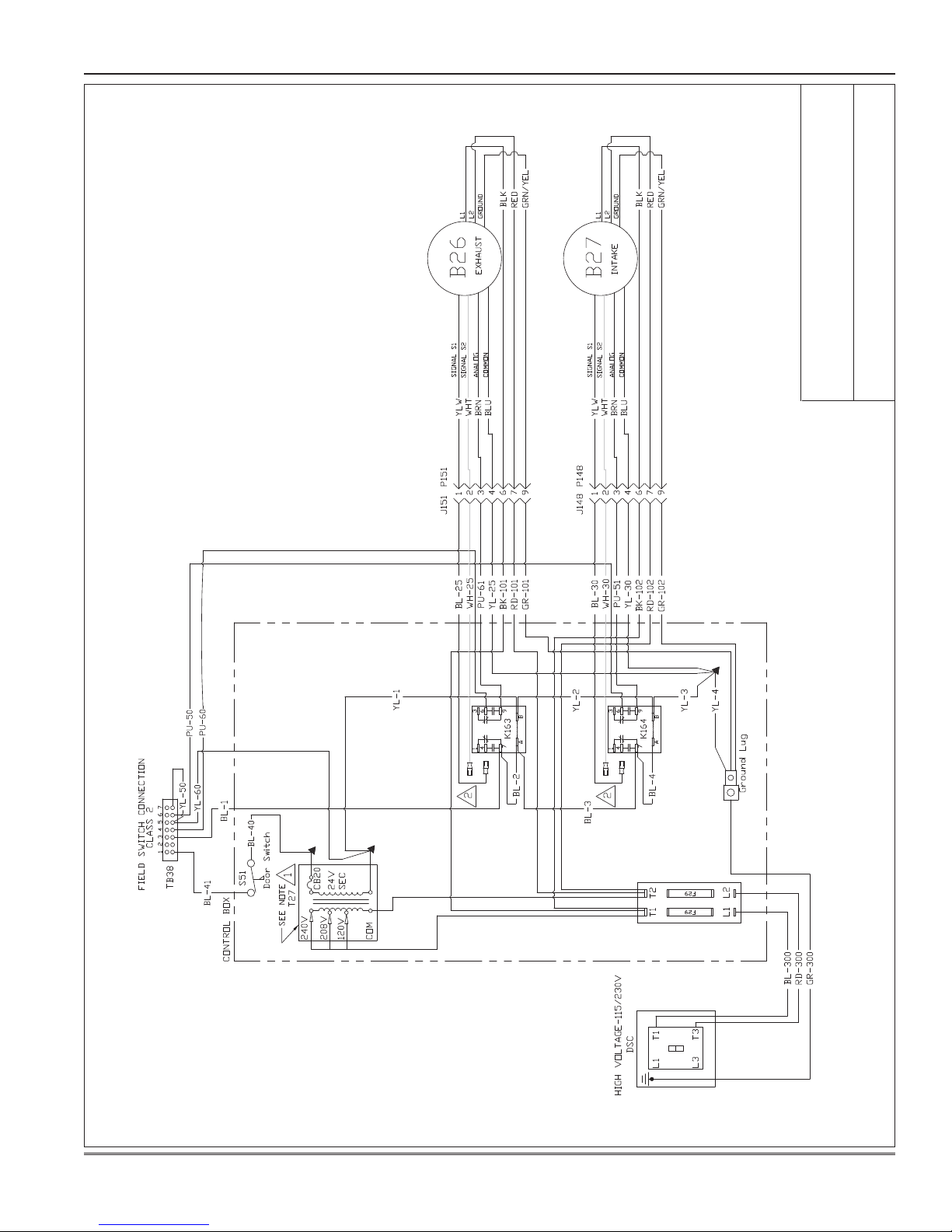
Variable speed ECM units: MiniCore Ventilators with
electronically commutated motors are shipped with blue
(BL-25 and BL-30) wires attached to terminal #1 of TB39
and TB40 in the blower compartment (See Figure ?)
locking the ECM in low speed mode, to switch to high speed
move the Blue wires to terminal #2. To use the Variable
speed option these blue wires need to be disconnected
from the relays (K163 & K164?) they are attached to and
0-10 VDC control wiring should be connected to terminals
4 through 7 detailed in the Low Voltage connections on
Page 2. See Wiring Diagram on Pages 7.
X - Maintenance
1. All motors use prelubricated sealed bearings; no
further lubrication is necessary.
2. Make visual inspection of lters, motor assemblies
and MiniCore Ventilator’s Heat exchange core during
routine maintenance.
3. Filters should be checked periodically and replaced
when necessary. Filters are located in front of Core
in the unit.

4 MC500-1ERV
Figure 6
A
A - Core Removal (See Figure 5)
1. Remove Access panels by opening each panel and
then releasing the spring loaded pins in the hinges by
pinching the tabs together.
2. Remove the center divider panel by removing the two
5/16" screws at with end of the panel on the side of the
MiniCore.
3. Carefully slide the core outwards.
B - Filter Removal (See Figure 6)
1. Open the Filter Access panel by opening the two
spring loaded latches to expose lters.
2. Slide lters outwards.
Figure 5
Unit A B C
MCV500 42 ¼51 15 ½
MCV1000 20 ¾
C
B

MC500-1ERV 5
Blower Data for PSC Motors
MCV 500 Cabinet
External Static Pressure 0.0 0.1 0.2 0.3 0.4 0.5 0.6 0.7 0.8 0.9 1.0
CFM
Low 649 634 586 510 402 313 233 129 NA NA NA
Medium 786 768 709 618 487 379 282 157 NA NA NA
High 957 935 927 929 900 853 800 738 688 632 535
MCV1000 Cabinet
External Static Pressure 0.0 0.1 0.2 0.3 0.4 0.5 0.6 0.7 0.8 0.9 1.0
CFM
Low 1146 1124 1079 1042 1006 969 895 918 892 853 826
Medium 1388 1361 1307 1262 1218 1174 1084 1112 1080 1033 1001
High 1618 1586 1524 1471 1420 1368 1264 1296 1259 1204 1166
Table #1
Performance Test for MCV500 with ECM Motor
Supply
External Static Pressure (in wc) 0.0 0.1 0.2 0.3 0.4 0.5 0.6 0.7 0.8 0.9 1.0
CFM
Input Voltage (v)
2259 253 158
3345 337 254 112
4431 421 350 232 83
5516 504 447 353 228 132 49
6602 588 543 473 373 290 216 120
7688 672 639 593 518 448 383 301 273 216 159
8773 755 736 714 663 607 551 481 472 430 389
9859 839 832 834 808 765 718 662 618 568 481
10 860 840 833 835 809 766 719 663 618 568 481
Exhaust
External Static Pressure (in wc) 0.0 0.1 0.2 0.3 0.4 0.5 0.6 0.7 0.8 0.9 1.0
CFM
Input Voltage (v)
238
3138 80 15
4238 182 121 52
5339 284 226 164 101 50
6439 386 332 275 216 164
7539 488 438 386 331 278 227 175 123 71 19
8640 590 543 498 446 393 347 298 249 200 151
9740 692 649 609 561 507 467 421 375 330 284
10 741 693 650 610 562 508 456 410 373 326 291
Performance Test for MCV1000 with ECM Motor
Supply
External Static Pressure (in wc) 0.0 0.1 0.2 0.3 0.4 0.5 0.6 0.7 0.8 0.9 1.0
CFM
Input Voltage (v)
2
3
4642 561 472 325
5795 734 664 575 459 301 123
6986 953 879 815 734 643 534 396 166
71237 1178 1129 1050 995 935 854 795 700 604 467
81377 1358 1347 1290 1214 1179 1114 1066 994 914 845
91408 1388 1392 1366 1339 1334 1300 1284 1263 1240 1186
10 1409 1394 1370 1349 1339 1317 1310 1290 1280 1255 1239
Exhaust
External Static Pressure (in wc) 0.0 0.1 0.2 0.3 0.4 0.5 0.6 0.7 0.8 0.9 1.0
CFM
Input Voltage (v)
2
3
4393 333 232 122
5582 508 420 346 208 137 36
6775 721 651 567 506 431 266 196 120
7974 915 860 796 735 671 588 522 414 284 208
81168 1119 1084 1028 987 938 881 837 757 694 612
91304 1270 1225 1187 1137 1094 1052 1004 945 888 801
10 1375 1352 1328 1308 1285 1232 1192 1159 1111 1071 1024

6 MC500-1ERV
MCV500 / MCV1000 UNIT WIRING DIAGRAM
Notes:
1. Selective voltage terminal for proper unit voltage.
Mini Ventilator W/ Factory Installed Options
115V / 230V (1 PH)
Unit#: 01-C45/C75/C150-02xH-01 / -21

MC500-1ERV 7
MCV500E / MCV1000E UNIT WIRING DIAGRAM
Notes:
1 Selective voltage terminal for proper unit voltage.
2 Omit BL-25, BL-30 for 0-10V Signal Control, Wire BL-25 to TB39-1 and BL-30 to TB40-1; for low speed, Wire BL-
25 to TB39-2, BL-30 to TB40-2; for high speed.
Mini Ventilator W/ Factory Installed Options
115V / 230V (1 PH)
Unit#: 01-C45/C75/C150-02xE-01 / -21

8 MC500-1ERV
INSTALLATION CHECK LIST
MiniCore Model # Serial #
Owner Owner Phone #
Owner Address
Installing Contractor Start Up Mechanic
Inspect the unit for transit damage and report any damage on the carrier's freight bill.
Check model number to insure it matches the job requirements.
Install eld accessories and unit adapter panels as required. Follow accessory and unit installation manuals.
Verify eld wiring, including the wiring to any accessories.
Check all multi-tap transformers, to insure they are set to the proper incoming voltage.
Verify blower wheels are centered. Realign if needed.
Prior to energizing the unit, inspect all the electrical connections.
Power the unit. Bump the motor relay to check rotation. If blower motor fans are running backwards, de-
energize power to the unit, then swap reversing plug on motors to change direction. Re-check.
Perform all start up procedures outlined in the installation manual shipped with the unit.
Fill in the Start Up Information as outlined on the opposite side of this sheet.
Provide owner with information packet. Explain the thermostat and unit operation.
START UP INFORMATION SHEET
VOLTAGE - MCV UNIT
Incoming Voltage L1-L2
Running Voltage L1-L2
Secondary Voltage
AMPERAGE - MCV MOTORS
Intake Motor: Nominal HP Rated Amps Running Amps
Exhaust Motor: Nominal HP Rated Amps Running Amps
Wheel Motor: Nominal HP Rated Amps Running Amps
AIRFLOW
Intake Design CFM Pressure Drop Calculated CFM
Exhaust Design CFM Pressure Drop Calculated CFM
Amb. db Temp Return Air db Temp* Tempered Air db Temp*
Amb. wb Temp Return Air wb Temp* Tempered Air wbTemp*
* Measure after 15 minutes of run time
This manual suits for next models
1
Other Ruskin Fan manuals
Popular Fan manuals by other brands

Soletric
Soletric RC51141 installation guide

Greenheck
Greenheck ESD-635D Installation, operation and maintenance manual

BLAUBERG Ventilatoren
BLAUBERG Ventilatoren Aero 100 user manual

Telstar
Telstar TVW018110MD manual

NuTone
NuTone QTXEN080FLT instruction manual

Harbor Breeze
Harbor Breeze HTD20005 quick start guide