Ruskin RRS ROOFTOP YCD/TCD User manual

INSTALLATION INSTRUCTIONS
ENERGY RECOVERY VENTILATOR
INSTALLATION INSTRUCTIONS FOR ENERGY RECOVERY VENTILATOR (FIXED) USED
WITH TRANE ROOFTOP UNIT MODELS YCD/TCD 15 TO 20 TON UNITS
R11A-10TDW
JULY 24, 2008
SUPERSEDES 10-09-06
I - Shipping And Packing List
Package 1 of 2 contains:
1 - Energy Recovery Wheel Assembly
1 - Outdoor Fresh Air Hood with Filter
1 - Outdoor Exhaust Hood with Filter
1 - Bag Assembly
a) Gasketing.
b) Foot pads
c) Hardware for standoff legs.
d) Wiring harness
e) Hardware for attachment to economizer.
Package 2 of 2 contains:
1 - Balancing Damper Assembly
2 - Filler Panels
1 - Top Adaptor Panel
1 - Platform Support Rail
II - Shipping Damage
Check unit for shipping damage. Receiving party should
contact last carrier immediately if shipping damage is
found.
III - General
These instructions are intended as a general guide and do
not supersede local codes in any way. Authorities having
jurisdiction should be consulted before installation.
IV - Requirements
When installed, the unit must be electrically wired and
grounded in accordance with local codes or, in absence of
local codes, with the current National Electric Code,
ANSI/NFPA No. 70.
V - Application
Energy Recovery Ventilators (ERV) are used with units
equipped with a return damper assembly. These wheels
conserve energy by mixing warmer air with cooler air in the
following manner:
Recovery Mode
The Recovery Mode is accomplished by two blowers
providing continuous exhaust of stale indoor air and
replacement by equal amount of outdoor air. Energy
recovery is achieved by slowly rotating the Energy
PAGE 1
Recovery Wheel (ERW) within the cassette frame work. In
winter, the ERW adsorbs heat and moisture from the
exhaust air stream during one half of a complete rotation
and gives them back to the cold, drier intake air supply
during the other half rotation. In summer, the process is
automatically reversed. Heat and moisture are absorbed
from incoming fresh air supply and transferred to the
exhaust air stream. This process allows outdoor air
ventilation rates to be increased by factors of three or more
without additional energy penalty or increase in size of
heating or air conditioning systems.
VI - Rigging Unit For Lifting
1. Maximum weight of unit is — 410 Lbs. (Crated)
2. Remove crating. Then remove access panel to
retrieve bag assembly. See Figure 1. Replace access
panel.
3. All panels must be in place for rigging.
4. Lifting straps are needed to lift the unit as shown in
Figure 1.
ACCESS PANEL
LIFTING STRAP
Figure 1
ETL Certified per UL 1995
and CSA 22.2
Energy recovery COMPONENT
certified to the AHRI Air-to-Air
Energy Recovery Ventilation
Equipment Certification Program in
accordance with AHRI Standard
1060-2000. Actual performance in
packaged equipment may vary.

4. Adjust balancing dampers to minimum air flow
requirements.
5. Attach wire harness using hardware provided in bag
assembly. Refer field wiring diagram. Route wiring
through return damper assembly.
6. Locate wire harness plug in exhaust air stream so
connection can be made with ERV after unit is set
place.
7. Install filler panels.
8. Position platform support rail with flange pointing away
from rooftop unit. Position using existing screw holes
and secure rail to rooftop unit base rail using provided
#14 screws.
9. Using lifting lugs, raise ERV unit approximately three
(3) feet. Remove nut and bolt assembly to slide
telescoping part of leg half way out of guide and attach
flat foot with hardware provided in bag assembly.
Position standoff legs so that flat foot is on bottom of
stand and reinstall nut and bolt assembly. DO NOT
fasten tightly, adjustment will need to be made when
unit is put into position. See Figure 2.
10. Attach provided gasketing material to face of ERV unit
to prevent air leakage.
11. Lift and move ERV unit into position in front of
horizontal exhaust air opening.
12. Lower ERV into platform support rail catching the front
edge of the ERV bottom into the flange. With the ERV
in place, adjust the standoff legs to level and support
ERV against rooftop unit filler panels. Use screws to
securely fasten ERV to rooftop unit. Tighten securely.
Rotate lifting lug to original position and tighten
machine bolts
13. Insert and secure top adaptor panel under top flange
of rooftop unit and against top flange of ERV.
PAGE 2
14. Seal, if required, along face (top and sides) of ERV unit
where it meets rooftop unit to insure no air leakage.
15. All electrical connections must conform to any local
codes and current National Electric Codes (NEC) and
Canadian Electric Codes (CEC). Refer closely to unit
wiring diagram in unit and/or in these instructions for
proper wiring connections. Refer to the unit nameplate
for minimum circuit ampacity and maximum
overcurrent protection size. Electrical data is listed on
unit rating plate and motor nameplates.
16. Remove ERV access panel to connect field wiring.
Connect wire harness plug and jack of ERV control
wiring together in exhaust air section.
17. Connect line voltage power supply to ERV unit from
disconnect switch.
18. Ground unit with a suitable ground connection either
through unit supply wiring or an earth ground.
Note: Unit voltage entries must be sealed weather
tight after wiring is complete.
19. Replace access panel onto the ERV unit and secure.
20. Attach wiring diagram (supplied) to rooftop unit wiring
diagrams.
21. Restore power to unit.
22. Cleanup once unit is operating properly, caulk any
open joints, holes or seams to make the units
completely air and water tight.
23. Leave this instruction manual with owner or in an
envelope to be kept near unit.
VIII - Operation
How It Works
The unit contains an Energy Recovery Wheel (ERW) that
is a new concept in rotary air-to-air heat exchanger.
Designed as a packaged unit for ease of installation and
maintenance, only matching up to rooftop unit with an
internal economizer and connection of electrical power is
WARNING
Electric shock hazard. Can cause injury
or death. Before attempting to perform
any service or maintenance, turn the
electrical power to unit OFF at
disconnect switch(es). Unit may have
multiple power supplies.
CAUTION
Danger of sharp metallic edges. Can cause injury.
Take care when servicing unit to avoid accidental
contact with sharp edges.
VII - Installation
1. Disconnect all power to rooftop unit.
Figure 2
TELESCOPING LEG
FOOT PAD
2. Remove the rooftop unit horizontal return air access
panels. Also remove any hoods and/or power exhaust
equipment. Discard hoods, power exhaust equipment
horizontal supply and return air access panels.

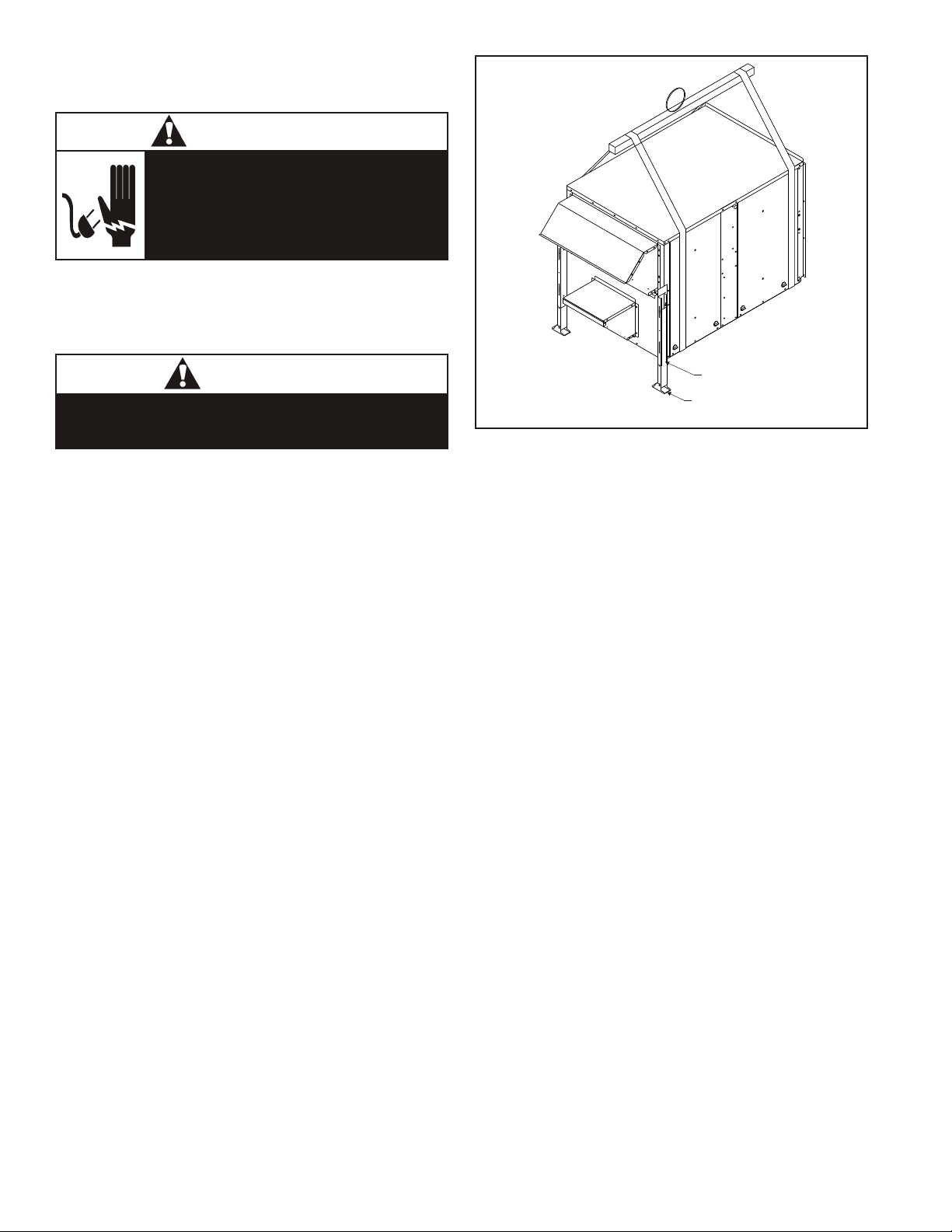
required to make the system operational. The concept
consists of a unique rotary energy recovery wheel that
rotates in and out of fresh air streams within a heavy duty,
permanently installed blower cabinet that provides ready
access to all internal components. The media is polymeric
material that is coated and permanently bonded with a dry
desiccant for total enthalpy recovery. The wheel is belt
driven by PSC motor and drive belt.
When slowly rotating through counter flowing exhaust and
fresh air streams the ERV adsorbs sensible heat and latent
heat from the warmer air stream and transfer this total
energy to the cooler air stream during the second half of its
rotating cycle. Rotating at 60 revolutions per minute, the
wheel provides constant flow of energy from warmer to
cooler air stream. The large energy transfer surface and
laminar flow through the wheel causes this constant flow
of recovered energy to represent up to 85% of the
difference in total energy contained within the two air
streams.
Sensible and latent heat are the two components of total
heat. Sensible heat is energy contained in dry air and latent
heat is the energy contained within the moisture of the air.
The latent heat load from the outdoor fresh air on an air
conditioning system can often be two to three times that of
the sensible heat load and in the winter it is a significant
part of a humidification heat load.
During both the summer and winter, the ERV transfers
moisture entirely in the vapor phase. This eliminates wet
surfaces that retain dust and promote fungal growth as well
as the need for a condensate pan and drain to carry water.
Because it is constantly rotating when in the air stream, the
ERV is always being cleared by air, first in one direction
then the other. Because it is always dry, dust or other
particles impinging on the surface during one half cycle,
are readily removed during the next half cycle.
Low Ambient Kit is appropriate for climates with limited
HVAC system operation when outdoor temperatures are
below 15oF.
The frost threshold is the outdoor temperature at which
frost will begin to form on the ERV wheel. For energy
recovery ventilators, the frost threshold is typically below
15oF. Frost threshold is dependent on indoor temperature
and humidity. The table shows how the frost threshold
temperatures vary depending on indoor conditions.
FROST THRESHOLD TEMPERATURE
INDOOR RH AT
70oF
FROST THRESHOLD
TEMPERATURE
20% 0oF
30% 5oF
40% 10oF
Because Energy Recovery Ventilators have a low frost
threshold, frost control options are not necessary in many
climates. Where outdoor temperatures may drop below
the frost threshold during the ERV operational hours,
exhaust only frost control option is available.
Low Ambient Kit
Low Ambient Kit turns off the supply blower when outdoor
temperatures fall below the frost threshold. Exhaust Only
set points are field adjustable with a factory supplied
thermostat. Supply fan operation is automatically restored
PAGE 3
when the exhaust air temperature rises above the
thermostat set point. Provisions for introducing make-up
air into the building when the supply blower is off to avoid
depressurization should be considered.
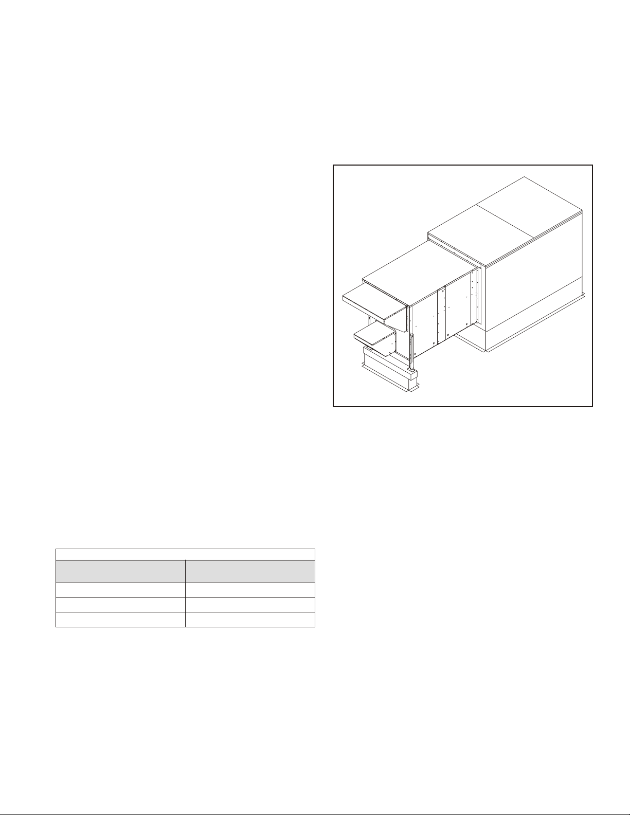
Recovery Mode
On a thermostat call for blower operation in heating,
cooling or continuous blower, the ERW will rotate between
fresh air and exhaust air streams. Both the fresh air and
exhaust air blowers will also be operating to overcome the
air resistance of the ERV. See Figure 3.
Figure 3
IX - System Check
1. Disconnect main power.
2. Turn thermostat to "Cont" for blower operation.
3. Restore power to unit. Observe ERV wheel rotation
and both fresh air and exhaust air blowers are
operating.
Note - If Low ambient kit is used the jumper between
TB37-5 & TB37-6 should be removed. Also if
system check out is being conducted at low
ambient temperatures, technician should be
aware that this kit can cause system not to
operate.
A - Return Damper Settings
Manually adjust position of dampers. This is accomplished
by loosing and tightening set screw on positioning rod.
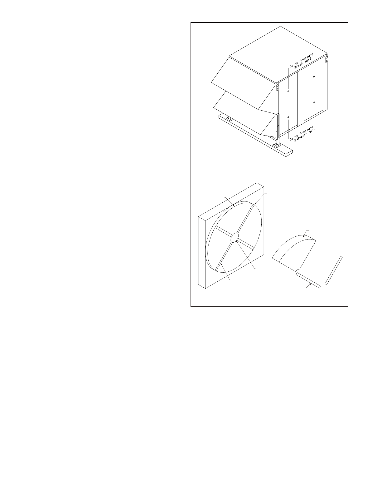
B - Blower Speed Adjustment
Blower speed selection is accomplished by changing the
speed tabs on both fresh air and exhaust air blowers. Both
blowers are factory set at "high speed" for maximum
airflow. To determine air flow setting, external static
pressure readings will need to be read across the ERV.
See Figure 4 for location to take pressure readings.
1. Disconnect main power to unit before making
adjustment to economizer and/or ERV unit.
2. Replace ERV control access cover.

PAGE 4
3. Set thermostat to normal operating position.
4. Restore power to unit.
X - Maintenance
Motor Maintenance
All motors use prelubricated sealed bearings; no further
lubrication is necessary.
Mechanical Inspection
Make visual inspection of dampers, linkage assemblies
and ERV rotating bearings during routine maintenance.
Filters should be checked periodically and cleaned when
necessary. Filter is located in fresh air hoods. DO NOT
replace permanent filters with throwaway type filters.
Energy Recovery Wheel Maintenance
Four pie-shaped ERW segments are seated on stops
between the stainless steel spring retainers, secured to
the hub and rim of wheel. Annual inspection of the self
cleaning wheel is recommended. With power
disconnected, remove ERV access panels (rear) and
unplug (J150 & P150). Refer to wiring diagram in this
instruction manual. Each segment is secured in place by a
stainless steel spring retainer located on wheel rim.
Remove one end of the stainless steel spring retainer from
the slot in the wheel rim and remove. Do the same on the
next retainer. Remove segment and wash with water
and/or mild detergent. Replace segment by reversing the
above procedure. See Figure 5. Discoloration and
staining of ERV segment does not affect its performance.
Only excessive buildup of foreign material need be
removed. If the segment appears excessively dirty, it
should be cleaned to ensure maximum operating
efficiency. Thoroughly spray plastic surface with
household cleaner such as Fantasticâor equivalent
middle detergent and gently rinse with warm water using a
soft brush to remove heavier accumulation. Shake excess
water from segment and replace in reverse of removal
instructions.
XI - WARRANTY
RSI Manufactured Parts
In the event that defects in workmanship or materials
originate in any part manufactured by RSI, FOB point of
manufactured, we guarantee to repair or replace that part,
within three (3) months of the shipment date.
Other Supplied Parts
Additionally, RSI guarantees to replace standard
components purchased new from a RSI vendor, (motors,
controls, etc.) that may be found defective, within twelve
(12) months of the installation date. The components
warranty, however, excludes service call charges and
labor cost for replacing or adjusting the defective part.
Limitation of Warranties
Misapplication, destruction, negligence or alteration
constitute the warranty and/or the components warranty of
RSI products and/or parts, null and void. This warranty is
provided in lieu of all other written, stated or implied
warranties.
HUB
SEGMENT
Figure 5
SPOKE
SEGMENT RETAINER CATCH
WHEEL RIM
SEGMENT RETAINER
Figure 4

PAGE 5
PAGE5
ENERGY RECOVERY VENTILATOR
0.8
0.85
0.9
0.95
1.00
1.05
1.10
1.15
1.20
1.25
1.30
1.27 1.26 1.25 1.23 1.2 1.18 1.17
1.15 1.13 1.12 1.09 1.06
0.99
0.91
1.05 1.02
0.95
0.8
0.65
0
0.2
0.4
0.6
0.8
1
1.2
1.4
700 750 800 850 900 950 1000 1050 1100 1150 1200
SCFM
Equation of Line: SCFM=(PD - 0.0568182)/0.0010455
TABLE #1
PRESSUREDROP(in.ofW.C.)
R11 Series Blow Hi Blow Med Blow Lo

R11-10TDW
ERV UNIT SCHEMATIC DIAGRAM COMPONENT CODE
A131 Fixed Relay Board
B26 Motor, Exhaust Air
B27 Motor, Fresh Air
B28 Motor, Desiccant Wheel
B30 Motor, Damper (Optional)
C23 Capacitor, Wheel Motor
C25 Capacitor, Motor Exhaust Air
C26 Capacitor, Motor Fresh Air
DL43 Delay, Cycle Timer (Optional)
F29 Fuse
J33 Jack, Cycle Control (Optional)
J34 Jack, Cycle Control Harness (Optional)
J40 Jack, Cycle (Optional)
J48 Jack, Control Box (Fresh Air)
J50 Jack, Control Box (Wheel)
J51 Jack, Control Box (Exhaust Air)
J56 Jack, Control Box (Damper)
J148 Jack, Fresh Air Motor Harness
J150 Jack, Wheel Motor Harness
J151 Jack, Exhaust Air Motor Harness
J152 Jack, Transformer (High Voltage)
J153 Jack, Field Harness
J160 Jack, Damper Motor Harness
K94 Relay, On/Off (Optional)
K163 Relay, Exhaust Air Motor
K164 Relay, Fresh Air Motor
P33 Plug, Cycle Control (Optional)
P34 Plug, Cycle Control Harness (Optional)
P40 Plug, Wheel Cycle (Optional)
P48 Plug, Fresh Air Motor Harness
P50 Plug, Wheel Motor Harness
P51 Plug, Exhaust Air Motor Harness
P56 Plug, Damper Motor Harness
P148 Plug, Fresh Air Motor
P150 Plug, Wheel Motor
P151 Plug, Exhaust Air Motor
P152 Plug, Transformer (High Voltage)
P153 Plug, Field Harness
P160 Plug, Damper Motor
S23 Thermostat - Low Ambient (Optional)
S26 Switch, Low Ambient (Optional)
S51 Switch, Door
S125 Switch, Ambient Override (Optional)
T27 Transformer, Control
T28 Transformer, Step-down (Optional)
T47 Transformer, Step-down (Optional)
TB57 Terminal Block - High Voltage
WIRE COLOR
BK Black
BL Blue
GR Green
GY Gray
OR Orange
Notes:
1. Remove jumper to install field optional low ambient switch.
2. Step-down transformer assembly for 460/575 volt units.
3. Selective voltage terminal for proper unit voltage
4. Optional low ambient switch.
5. Optional motorized intake damper.
6. Unit may be wired for HI, MED, or LO speeds. Diagram shows the HI speed setup, to rewire for MED or LO speed, disconnect
BK-101 from relays and connect BL-101 for MED, or RD-101 for LO. Also connect WH-101 to BK-101.
7. Optional stop, start and jog control.
8. Matching adapter harness (provided) to connect with rooftop unit. For energy management systems connect +24v to green
and common 24v to black.
PAGE 6

PAGE 7
Unit#: 01-R11-01XX-11 thru -43
Desiccant Wheel for Rooftop Unit
208-230/460/575V (1 ph & 3ph)
Notes:
1. Remove jumper to install field optional low ambient switch.
2. Step-down transformer assembly for 460/575 volt units.
3. Selective voltage terminal for proper unit voltage
4. Optional low ambient switch.
5. Optional motorized intake damper.
6. Unit may be wired for HI, MED, or LO speeds. Diagram shows the HI speed setup, to rewire for MED or LO speed, disconnect BK-101 from relays and connect BL-101
for MED, or RD-101 for LO. Also connect WH-101 to BK-101.
7. Optional stop, start and jog control.
8. Matching adapter harness (provided) to connect with rooftop unit. For energy management systems connect +24v to green and common 24v to black.
ERV UNIT WIRING DIAGRAM

PAGE 8
Table of contents
Other Ruskin Fan manuals
Popular Fan manuals by other brands

Parrot Uncle
Parrot Uncle F8215110V Installation & operating instructions

Broan
Broan L100 Series instructions

Vent-Axia
Vent-Axia T-Series Installation & user's instructions

Modern Forms
Modern Forms Renegade 52 installation instructions

Brink
Brink Flair 450 Installation regulations

Hunter
Hunter Hunter Ceiling Fan instruction manual

Swegon
Swegon WISE Parasol a Instructions for use

Mitsubishi Electric
Mitsubishi Electric LGH-50RSDC-E1 Handbook

Professional Series
Professional Series PS-ISF229 user manual

Lasko
Lasko 4930 operating manual

Bahamas Breeze
Bahamas Breeze FS45-3ER owner's manual

Aereco
Aereco VCR-HD TECHNICAL AND MAINTENANCE DOCUMENTATION