Release Date: 6/15/2021Page 2
TDFi-RT Advanced Thermal Dispersion Fan Inlet
Airflow & Temperature Measuring System
Technical Bulletin
TDFi-RT Refer to the Ruskin.com website for the most up-to-date version of this document.
DOCUMENT INTRODUCTION....................................................................................................... 3
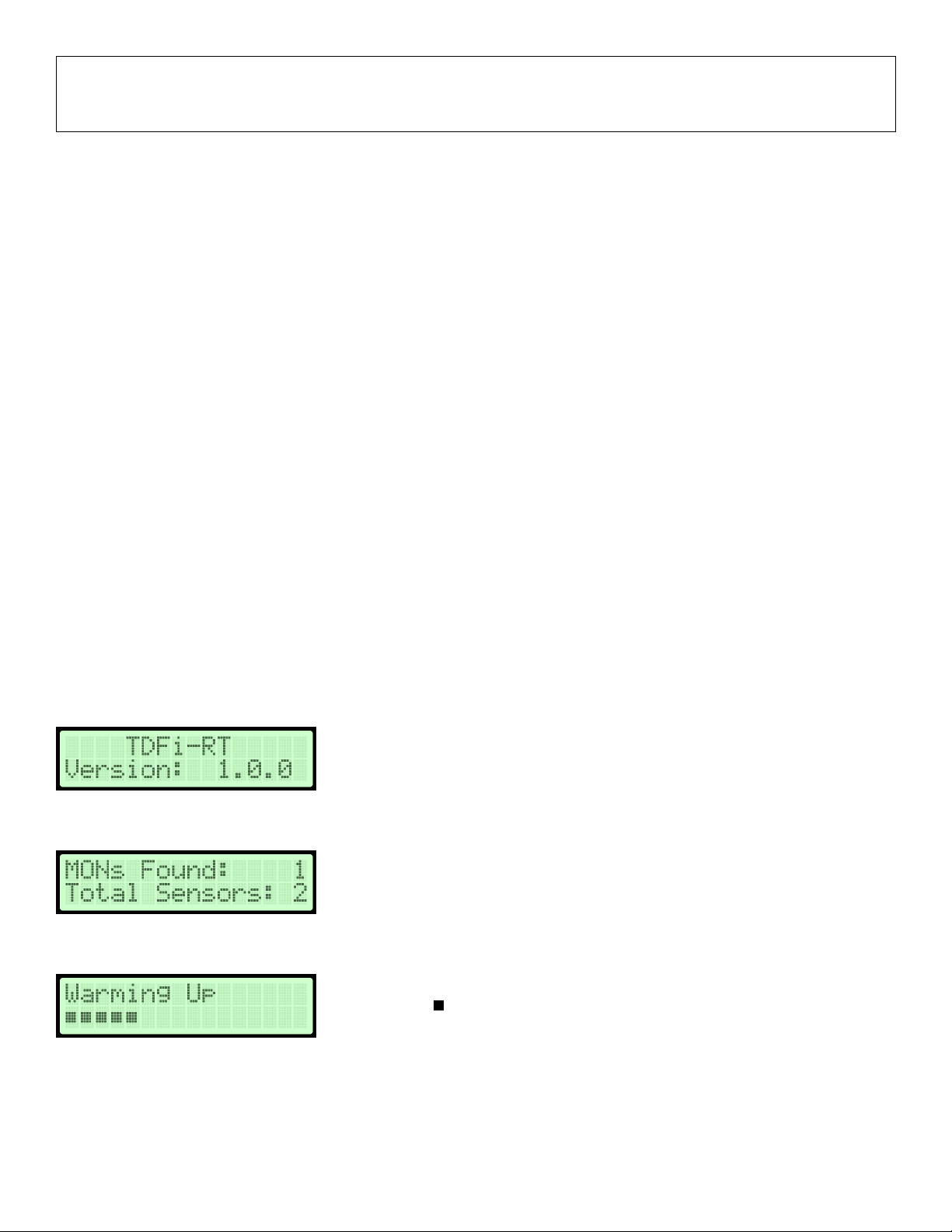
START-UP................................................................................................................................... 3
Navigating the Start-Up Menu .........................................................................................................................................3
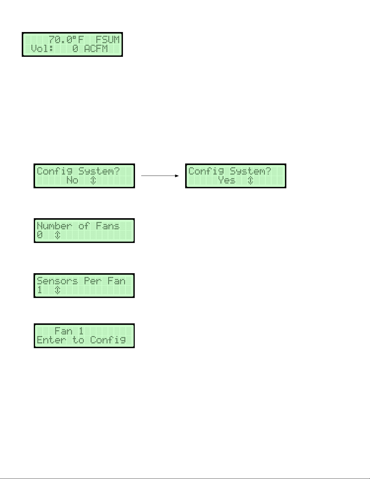
NORMAL OPERATION ................................................................................................................. 4
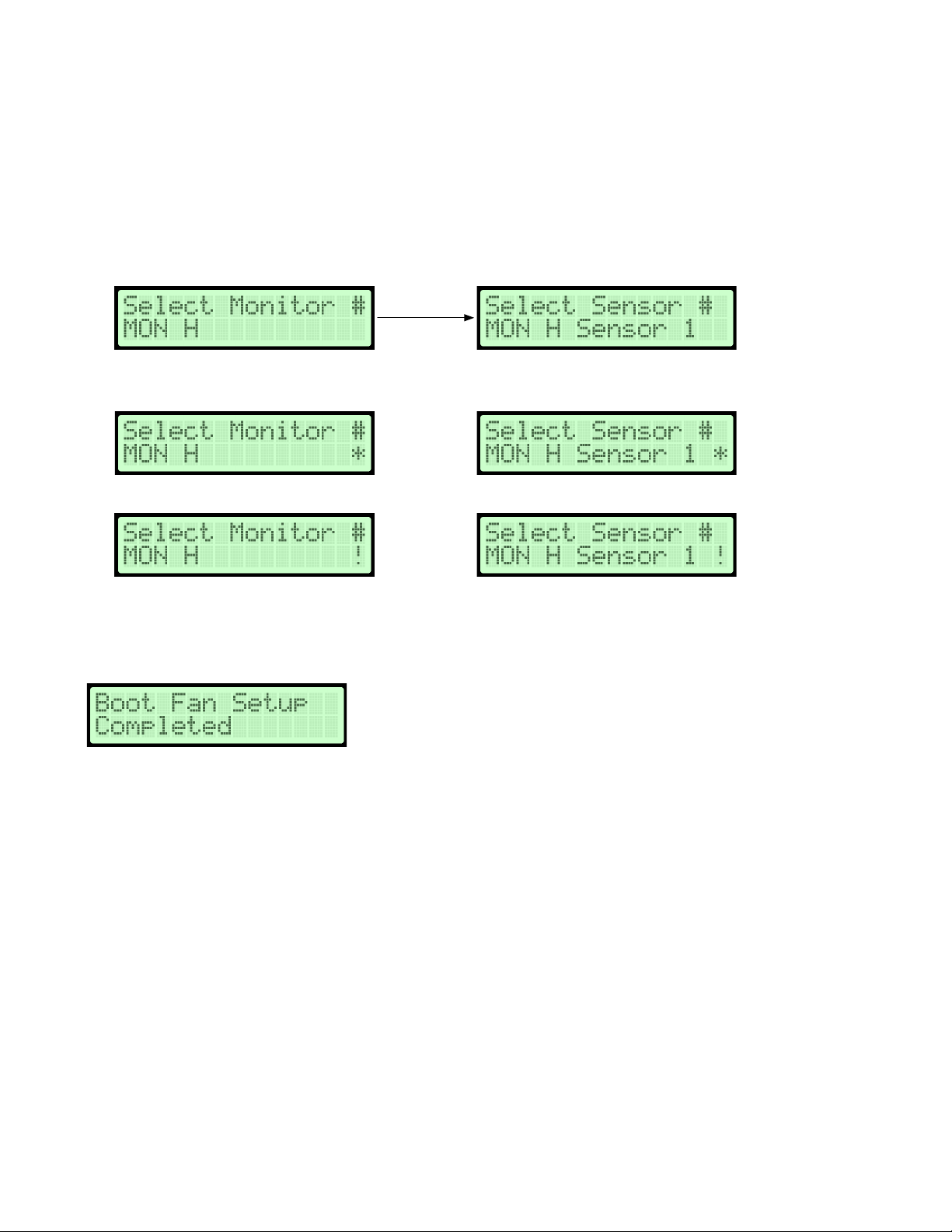
BOOT FAN SETUP ....................................................................................................................... 4
NORMAL OPERATION ................................................................................................................. 5
Configuration ...................................................................................................................................................................5
Membrane Push Buttons ..................................................................................................................................................5
Normal Operation Display Mode ......................................................................................................................................6
NAVIGATING THE MENU OPTIONS .............................................................................................. 6
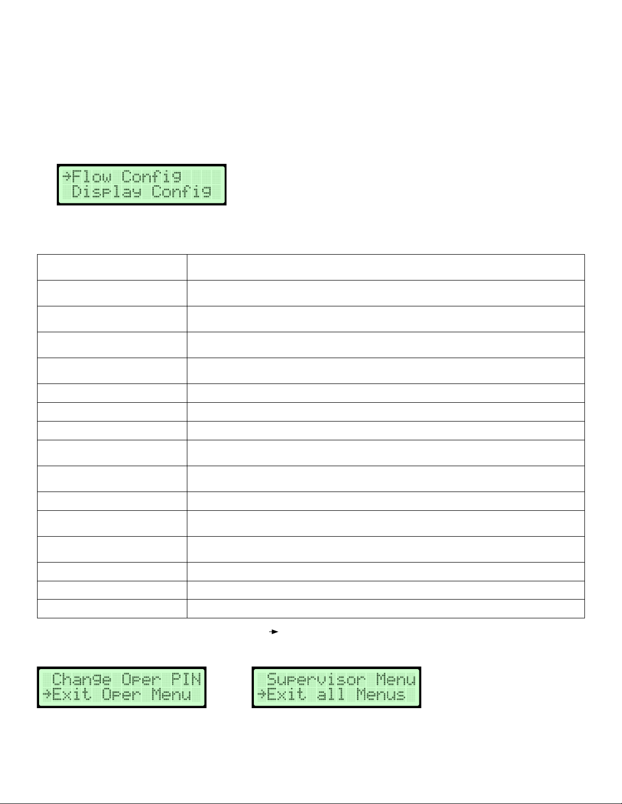
Navigating The Operator Menu.........................................................................................................................................6
Operator Sub-Menu Example ...........................................................................................................................................8
Operator Pin Selection .....................................................................................................................................................9
Flow Configuration .........................................................................................................................................................10
Display Configuration .....................................................................................................................................................12
Analog Output 1 Parameters ..........................................................................................................................................14
Analog Output 2 Parameters ..........................................................................................................................................15
Temperature Output LPF (Low Pass Filter) .....................................................................................................................16
Flow Output LPF (Low Pass Filter) ..................................................................................................................................17
Analog Output Calibration ..............................................................................................................................................18
Temperature Balance Configuration ................................................................................................................................22
Menu Time-Out .............................................................................................................................................................24
BACnet Network Configuration .......................................................................................................................................25
BACnet Flow Alarm Configuration...................................................................................................................................26
BACnet Temperature Alarm Configuration ......................................................................................................................28
NAVIGATING THE SUPERVISOR MENU ...................................................................................... 30
Introduction.....................................................................................................................................................................30
Supervisor Pin Selection ................................................................................................................................................32
Sensor Management ......................................................................................................................................................33
Fan Array Configuration .................................................................................................................................................37
Fan Field Calibration – Manual ........................................................................................................................................40
Fan Field Calibration – Calculated ...................................................................................................................................42
Fan Field Calibration – Automatic Calibration Process ....................................................................................................44
Fan Field Calibration – View Field Calibration Process....................................................................................................45
Fan Field Calibration - Fan Array Calibration Process......................................................................................................45
Fan Array Field Calibration – Calibration Error Screens...................................................................................................47
Factory Default Reset......................................................................................................................................................49
Supervisor Pin Selection ................................................................................................................................................50
TROUBLESHOOTING.................................................................................................................. 51