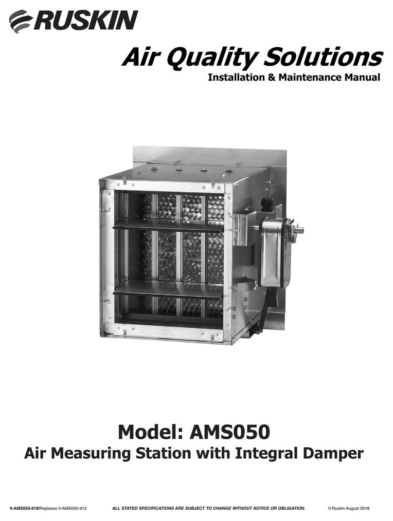
Ruskin AMS Instruction Manual

Air Quality Solutions
Installation & Maintenance Manual
Model: AMS
Air Measuring Station
II-AMS-818/New
ALL STATED SPECIFICATIONS ARE SUBJECT TO CHANGE WITHOUT PRIOR NOTICE OR OBLIGATION
© Ruskin August 2018

Product Application............................................................................................................................................................................2
Key Features .....................................................................................................................................................................................2
Key Benets .......................................................................................................................................................................................2
Construction Details...........................................................................................................................................................................3
Installation ..........................................................................................................................................................................................3
Installations Air Measurement Station Placements............................................................................................................................4
Duct Diameter Equivalents Chart .......................................................................................................................................................5
Sequence of Operation ......................................................................................................................................................................6
Standard RU-274-R2-VDC Transducer Wiring Details ......................................................................................................................7
Specications.....................................................................................................................................................................................8
Maintenance.......................................................................................................................................................................................8
TABLE OF CONTENTS
! WARNING
READ THESE INSTRUCTIONS CAREFULLY BEFORE ATTEMPTING TO INSTALL, OPERATE OR SERVICE
THIS DEVICE.
THIS ACCESSORY IS TO BE INSTALLED BY A QUALIFIED SERVICE TECHNICIAN. TO AVOID UNSATISFAC-
TORY OPERATION OR DAMAGE TO THE PRODUCT AND POSSIBLE UNSAFE CONDITIONS, INCLUDING
ELECTRICAL SHOCK AND FIRE, THE INSTALLATION INSTRUCTIONS PROVIDED WITH THIS ACCESSORY
MUST BE STRICTLY FOLLOWED AND THE PARTS SUPPLIED USED WITHOUT SUBSTITUTION. DAMAGE
TO THE PRODUCT RESULTING FROM NOT FOLLOWING THE INSTRUCTIONS OR USING UNAUTHORIZED
PARTS MAY BE EXCLUDED FROM THE MANUFACTURER’S WARRANTY COVERAGE.
! WARNING
DISCONNECT ELECTRICAL POWER PRIOR TO SERVICING THIS UNIT. FAILURE TO DO SO CAN RESULT IN
ELECTRICAL SHOCK RESULTING IN PERSONAL INJURY OR DEATH.
2
Product Application
The Air Measuring Station (AMS) is designed to be used in any application that requires accurate airow measurement
at velocities between 300 and 5,000 feet per minute (1.5 and 25 m/s). Unit may be installed in the duct or in an air
handling unit and can be used to measure outside air, return air, discharge air or exhaust air ows into or out of a
building or air handling unit.
Key Features
• Licensed to bear the AMCA Certied Ratings Seal for Airow Measurement Station Performance
• Combines Ruskin’s exclusive anodized aluminum step sensor with a 3” (76mm) deep 3000 series aluminum
honeycomb air straightener for accurate measurement to maximize performance and oer repeatable and
accurate results.
• Velocity Pressure with Dead-Head transducer.
• Field selectable pressure ranges for greatest measurement resolution.
Key Benets
• Contributes to earning required Indoor Environmental Quality (EQ) and Energy and Atmosphere (EA) LEED
prerequisites.
• Save energy dollars by measuring the minimum ventilation airow.
• Meet International Building Code (IBC) and International Energy Conservation Code (IECC) requirements.
• Maintain proper ventilation to dissipate dangerous indoor contaminants such as mold spores, bacteria and
chemicals.
• Create a healthy indoor environment to reduce absenteeism, increase productivity, improve comfort and
reduce the risk of litigation
Construction Detail
3
The AMS is an air measuring device that uses
pressure across a series of step sensor blades to
measure air ow. The step sensor blades are rugged
anodized aluminum extrusion with holes arranged
to pick up the average total and staic pressures in
the system. Total and Static pressure points are
piped to a pressure transducer* with an internal
glass-on-silicone GL-Si capacitance sensor that is
accurate to 1% of full scale.
The AMS air measuring device is available with
optional front ange, rear ange, double (front and
rear) ange or oset ange.
Refer to the sequence of operation section on page
6 of this document for further details.
Static Pressure
Measuring Chamber
Total Pressure
Measuring Chamber
AIR FLOW
MOUNTING FLANGE OPTIONS
AMS SENSING BLADE DETAIL
FRONT FLANGE
(Code F)
REAR FLANGE
(Code R)
DOUBLE (FRONT &
REAR) FLANGE
(Code D)
OFFSET FLANGE
*Specify Dimensions
(Code O)
Honeycomb
Straightener
Tubing Shield
Flow
Arrow
Anodized
Flow Sensor
AIR FLOW
1.50"
(38)
x
1.50"
(38)
1.50"
(38)
NOTE: Pressure transducer may be removed and relocated during
installation. Orientation is critical. Refer to Installation Instructions.
1.50"
(38)
1.0"
(25)
9.0"
(229)
High & Low
Pressure Ports
Installation
Please verify that you have received everything noted on the packing slip prior to proceeding with the installation.
Remove the AMS from its shipping container and inspect for damage, rust or corrosion. Care must be taken in
handling the unit. Always handle the AMS by its frame. Do not drop, drag, step on or apply excessive bending,
twisting, or racking loads to the AMS. Special care should be used to protect the honeycomb staightener. Slight
cosmetic damage to the air straightener may occur in shipment and will not eect air measurement performance.
Simply straighten with long nose pliers if necessary to allow air to pass freely through the straightener.
1. Inspect the duct work and/or opening where the AMS assembly will be installed. If it is to be installed
in ductwork, the ductwork should be supported at the area of the AMS to prevent sagging due to the
unit’s weight.
2. The AMS must be installed with the frame square and without twisting or bending.
3. The AMS has a specied inlet and outlet. The outside air (or other controlled air stream) enters the
unit through the air straightening section.
4. Use appropriate shims between the damper frame and ducts opening to prevent distortion of the
frame by fasteners holding it in place. If creating a multi-section assembly, be sure that all the sections
are fastened together on both sides.
5. After installing the assembly in the ductwork or moutning hole, caulk around the frame to prevent
leakage or bypass air around the air measuring station.
6. Refer to page 4 for acceptable application specic air measuring product placement options.
Consult your local representative with questions about placement.

4
5
Air Measurement Station Placements for Ideal Installations
Air Measurement Station Placements for Acceptable Installations

5
(:/0?0=8490?30;7,.0809?:1,9,4=80,>@=492>?,?4:9?3,?4>7:.,?0//:B9>?=0,8:1,IA,90/07-:B
,>>3:B949?30/0?,47,-:A01:77:B?30/@.?B4/?3/:B9?:?30/@.?30423?(309@8-0=,??34>
49?0=>0.?4:9=0;=0>09?>/4>?,9.04949.30>
C,8;70
(30<@4A,709?:1,GCG/@.?G
C,8;70
(30>,80GCG/@.?49>?,770/,>>3:B949/0?,47B:@7/-0GC
#:?0>
779@8-0=>,=00C;=0>>0/4949.30>
CC0?.
6
1. All numbers are expressed in inches.
2. 2D = 1D x 2, 3D = 1D x 3, etc.
3. Equivalent round duct diameter = SQRT ([4 x H x W] ÷ 3.1416)
To determine the placement of an air measuring station that is located down stream of a 90º vaned elbow (as shown
in the detail E1 above); follow the duct width down to the duct height. The number at this intersection represents
distance in inches (1D).
Example 1
The 1D Equivalent of a 20” x 10” duct = 16”
Example 2
The same 20” x 10” duct installed as shown in detail E3 would be 16” x 5 (5D)
Notes:
1. All numbers are expressed in inches.
2. 2D = 1D x 2, 3D = 1D x 3, etc.
3. Equivalent round duct diameter = SQRT ([4 x H x W] ÷ 3.1416)

6
Sequence of Operation
BAS Control
The unit is installed and furnished with an RU274R2VDC transducer. Under ow, the transducer output produces a
voltage signal to the Building Automation System (BAS). The BAS calculates CFM based on the velocity pressure.
CFM can be checked by referencing the chart or by utilizing the formula below. Both Ka and 1/m values are constants
that may change based on the size of the air measurement station.
The formula provided on the PAMS (Pressure Across Measuring Station) chart must be applied to convert the
velocity pressure output from the low-pressure transducer into a CFM value. Each unit is provided with a PAMS chart
developed specically for that unit. Applying other formulas may result in greater air measurement error and
unacceptable results.
CFM=(AREA * Ka) * PAMS(l/m)
SOLD TO: Ruskin Customer
CONTROL NO: 1234567
TAG: Unit 1
MODEL: AMS
Ka 3047.4
Damper Width 48 1/m 0.5222
Damper Height 73 Area x Ka = 70730.154
Number Probes 4Area = 23.21
Damper Sections 1
CFM
4,446
6,386
9,171
11,333
13,170
14,798
16,276
17,641
18,915
20,115
21,252
22,337
23,375
24,373
25,335
26,264
30,521
37,719
43,833
49,250
54,170
58,710
62,950
66,944
70,730
*PAMS = Pressure Across Measuring Station
NOTE:
CFM CORRECTED TO 70° F. & 1000 FT ELEVATION.
FOR OTHER ELEVATIONS ADD 2% PER 1000 FT. INCREASE
ADD 1% PER 10° F INCREASE IN TEMP.
RECOMMENDED OPERATING RANGE IS 300 TO 2000 FPM.
OPERATION OUTSIDE THE OPERATING RANGE IS NOT RECOMMENDED
0.80
2,712
0.90
2,884
1.00
3,047
0.50
2,122
0.60
2,334
0.70
2,530
0.20
1,315
0.30
1,625
0.40
1,889
0.13
1,050
0.14
1,092
0.15
1,132
0.10
916
0.11
962
0.12
1,007
0.07
760
0.08
815
0.09
867
0.04
567
0.05
638
0.06
701
0.01
275
0.02
395
0.03
488
Actual Damper Size (inches)
CFM = (AREA * Ka) * PAMS(1/m)
PAMS* FPM
0.005 192

7
Standard RU-274-R2-VDC Transducer Dip Switch Settings and Wiring Details
The Default Settings for S1, S2, and S3 are, 1-ON, 2-OFF
For other settings and pressure ranges consult transducer product data sheet
Follow the steps below to set up the standard RU-274-R2-VDC low-pressure transducer. The default
settings are shown above for a 0-10VDC output and a 0-1.0 inwc pressure range. Normal power
source is 24VAC however 12 to 40VDC or 12 to 35VAC are also acceptable.
1. The terminal block can be wired by carefully unplugging it from the circuit board.
2. Locate the (+) (-) and the (O) terminal markings on the circuit board.
3. Attach the power wires to the respective (+) and (-) terminals. Note: the (-) terminal is also the
negative output termination point.
4. Connect the (O) terminal, which is the positive VDC output terminal, to the BAS input.
5. Verify the VDC output with a digital volt meter connected to the (O) and (-) terminals.
6. Voltage output signal and differential pressure range are dipswitch selectable. Reference the
installation instructions for the low-pressure transducer for additional information.
8
Follow the steps below to set up the standard RU-274-R2-VDC low-pressure transducer. The default
settings are shown above for a 0-10VDC output and a 0-1.0 inwc (249 Pa) pressure range. Normal
power source is 24VAC however 12 to 40VDC or 12 to 35VAC are also acceptable.
Follow the steps below to set up the standard RU-274-R2-VDC low-pressure transducer. The settings are
shown above for a 0-10VDC output and a 0-1.0 inwc pressure range. For the greatest air measurement
resolution, use the lowest pressure range that will work for the maximum airow expected.
Normal power source is 24VAC however 12 to 40VDC or 12 to 35VAC are also acceptable.
1. The terminal block can be wired by carefully unplugging it from the circuit board.
2. Locate the (+) (-) and the (O) terminal markings on the circuit board.
3. Attach the power wires to the respective (+) and (-) terminals. Note: the (-) terminal is also the
negative output termination point.
4. Connect the (O) terminal, which is the positive VDC output terminal, to the BAS input.
5. Verify the VDC output with a digital volt meter connected to the (O) and (-) terminals.
6. Voltage output signal and dierential pressure range are dipswitch selectable. Reference the
installation instructions for the low-pressure transducer for additional information.
Standard RU-274-R2-VDC Transducer Dip Switch Settings and Wiring Details
12-35 VAC or VDC
Power Supply
0-10 VDC Output
Controller/Meter
The Default Settings for S1, S2, and S3 are, 1-ON, 2-OFF
For other settings and pressure ranges see table below, or consult transducer product data sheet
Range Conguration - Uni-directional
Switch - S1
R2 0-1.0” wc/250 pa (default)
0-0.5” wc/125 pa
0-0.25” wc/62.5 pa

3900 Dr. Greaves Rd.
Kansas City, MO 64030
(816) 761-7476
FAX (816) 765-8955
www.ruskin.com
®
3900 Dr. Greaves Rd.
Kansas City, MO 64030
(816) 761-7476
FAX (816) 765-8955
www.ruskin.com
®
Wiring and Piping Connections
The AMS Air Measuring Station will be shipped with a Ruskin low-pressure transducer. The standard transducer is a
Ruskin RU-274-R2-VDC and is factory congured for 0-1.0 inwc (0-249 Pa) corresponding to a 0-10VDC output. The
transducer requires a power source of either 12-40VDC or 12-35VAC. Connect pressure tubing from the transducer
to the airow sensing blade, connecting the low pressure port to the static pressure side nearest the air exiting side
and the high pressure port to the blade side facing the air entering side. Optional transducers with LCD displays or
0-20mA output are also available.
Specications
RU-274-R2-VDC Transducer (low pressure transducer)
Power 12-40 VDC or 12-35 VAC
Outputs 0-10 VDC (0-5 VDC eld selectable)
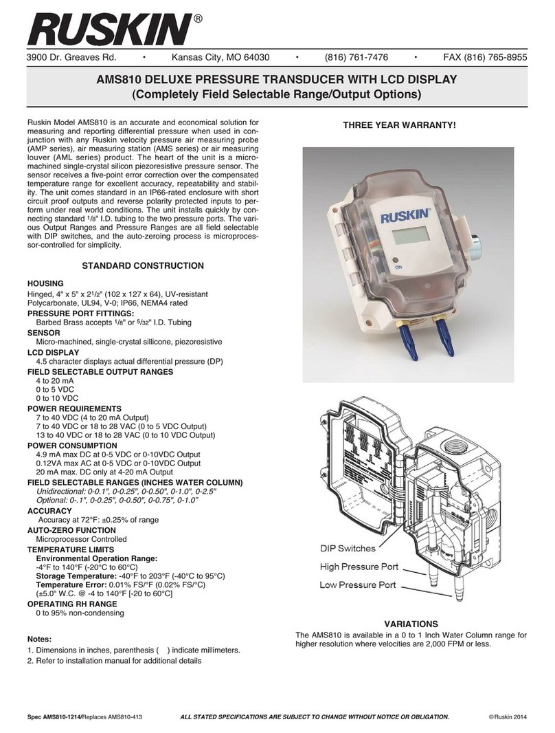
Optional 4-20 mA Order AMS810 Transducer
Enclosure Painted NEMA 4 (IP-65)
Operating Range °F to 175°F (-18°C to 80°C)
Maintenance
1. Disconnect the sensing tubes between the damper and the pressure transducer. Apply a clean pressurized air
source, less than 10 PSI, to the air piping connections at the AMS frame in order to blow out any condensation
or dirt accumulation plugging the sensing ports. DO NOT connect this air source to the pressure transducer.
This will damage the instruments. Replace tubing to the equipment in reverse order of removal.
2. The air straightener section of the AMS and the air sensing blades should be annually inspected for particulate
build-up. Use a damp cloth to wipe clean the sensing blade surface. Water may be used to clean and ush
the air straightening section and the sensing blades of the AMS. Using pressurized air for purging the sensing
blades of water is recommended.
AMS STANDARD CONSTRUCTION
SLEEVE
9” (229) long x 16 ga. (1.6) galv. G60 (for slip-t duct
connection).
AIR FLOW STRAIGHTENER
.50” (13) Honeycomb Cell x 3” (76) 3000 series
aluminum alloy.
SENSOR BLADE
6063T6 extruded aluminum, clear anodize nish.
SENSOR PORT FITTINGS
Brass.
ACCURACY
3% deviation average across measurement range.
OPERATING TEMPERATURE
-22° F to +140° F standard (-30°C to 60°C).
VELOCITY
Product Range - 300 to 5000 FPM (1.5 to 25 m/s).
Operating Range - 300 to 2,000 FPM (1.5 to 10.2 m/s).
-Standard units with RU274-R2-VDC (1.5 to 25 m/s).
Operating Range - 300 to 5,000 FPM (1.5 to 25 m/s).
Units with AMS810 high pressure transducer.
MINIMUM SIZE
Single - 6”w x 6”h (152 x 152).
MAXIMUM SIZE
Single section - 60”w x 72”h (1524 x 1829).
Multiple section assembly - 120”w x 72”h (3048 x 1829).
Table of contents
Other Ruskin Measuring Instrument manuals

Ruskin
Ruskin EFAMS Manual

Ruskin
Ruskin AMS050 Instruction Manual

Ruskin
Ruskin EFAMS Instruction Manual

Ruskin
Ruskin TDFi-RT Manual

Ruskin
Ruskin DPT-IQ Instruction Manual

Ruskin
Ruskin TDP05K Instruction Manual

Ruskin
Ruskin AIRFLOW-IQ User manual

Ruskin
Ruskin AMS810 User manual

Ruskin
Ruskin TDP05K Service manual

Ruskin
Ruskin TDFi-RT Service manual