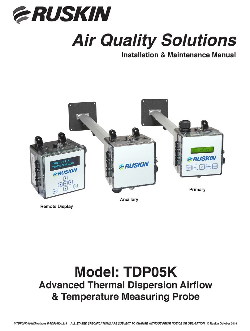
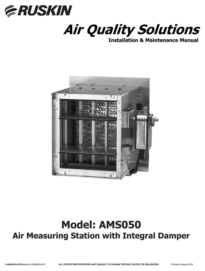
Ruskin TDP05K Service manual

Air Quality Solutions
Technical Bulletin
Model: TDP05K
Advanced Thermal Dispersion Airflow
& Temperature Measuring System
ALL STATED SPECIFICATIONS ARE SUBJECT TO CHANGE WITHOUT PRIOR NOTICE OR OBLIGATION ©Ruskin June 2022TB-TDP05K-0622/New

TDP05K Advanced Thermal Dispersion Probe Airflow Measuring System Technical Bulletin Release Date: 06/2022Page 2
TDP05K Advanced Thermal Dispersion
Airflow & Temperature Measuring System
Technical Bulletin
TDP05K Refer to the Ruskin.com website for the most up-to-date version of this document.
DOCUMENT INTRODUCTION....................................................................................................... 3
NAVIGATING THE START-UP MENU............................................................................................. 3
NORMAL OPERATION ................................................................................................................. 4
CONFIGURATION ........................................................................................................................ 4
MEMBRANE PUSH BUTTONS ..................................................................................................... 4
NAVIGATING THE MENU OPTIONS .............................................................................................. 5
NAVIGATING THE OPERATOR MENU............................................................................................ 5
Enable, Disable, and Change the Operator PIN ................................................................................................................7
Flow Configuration ...........................................................................................................................................................8
Display Configuration ......................................................................................................................................................10
Selecting Custom Text ....................................................................................................................................................11
Analog Output 1 Parameters...........................................................................................................................................11
Analog Output 2 Parameters ..........................................................................................................................................11
Temperature Output LPF (Low Pass Filter) .....................................................................................................................12
Flow Output LPF..............................................................................................................................................................13
Analog Output Calibration ..............................................................................................................................................14
Calibrating the Analog Output.........................................................................................................................................15
Temperature Balance Configuration ...............................................................................................................................17
K-Factor Configuration....................................................................................................................................................18
Configuring the K-Factor.................................................................................................................................................19
Automatic Calculation of K-Factor Not Enabled ..............................................................................................................20
Automatic Calculation of K-Factor Enabled.....................................................................................................................20
Menu Timeout.................................................................................................................................................................22
BACnet Network Configuration .......................................................................................................................................23
Modbus RTU Network Configuration ...............................................................................................................................24
RS-485 Interface Flow Alarm Configuration ...................................................................................................................25
RS-485 Interface Temperature Alarm Configuration.......................................................................................................26
NAVIGATING THE SUPERVISOR MENU ...................................................................................... 27
Enable, Disable, and Change the Supervisor PIN.............................................................................................................28
Sensor Management ......................................................................................................................................................29
Reset Sensor Network ....................................................................................................................................................32
Factory Default Reset......................................................................................................................................................33
TROUBLESHOOTING.................................................................................................................. 35

Release Date: 06/2022TDP05K Advanced Thermal Dispersion Probe Airflow Measuring System Technical BulletinPage 3
DOCUMENT INTRODUCTION
This document describes the TDP05K Advanced Thermal Dispersion Probe Airflow Measuring System’s features and functions. It also
provides guidelines and instructions for setting up and troubleshooting these devices used in plenum and duct applications.
NAVIGATING THE START-UP MENU
After installing the TDP05K Airflow Measuring System, power on the unit. Menu options appear on the front panel LCD display of the
primary controller and are replicated on the remote user interface (see Figure 1). The LCD display has a 16 character per line, 2-line
display.
Figure1: Front Panel LCD Display of Primary TDP05K Controller & Remote User Interface
The display boot screen indicates the firmware version.
After 5 seconds, the display indicates the number of active probes and sensors. This example indicates one active probe and four total
sensors.
After another 5 seconds, the display indicates that the unit is warming up.
TDP05K Advanced Thermal Dispersion Probe Airflow Measuring System
Technical Bulletin

TDP05K Advanced Thermal Dispersion Probe Airflow Measuring System Technical Bulletin Release Date: 06/2022Page 4
NORMAL OPERATION
The normal operation screens display the average temperature and average velocity or volume in the units selected. When the display is
configured for the International System of Units (SI), the display shows the temperature in Celsius and the average velocity in meters per
second or the volume as liters per minute. See Table 3 for the available units.
When the display is configured for Imperial, the display shows the temperature in Fahrenheit and the average velocity in Actual Cubic Feet
per Minute. See Table 3 for the available units.
You can use these push buttons during system configuration setup and while performing certain functions in the normal operation mode.
NOTE: An asterisk (*) appears on the top left corner of the display if the number of sensors has changed during normal operation mode.
CONFIGURATION
The on board microprocessor in the TDP05K primary probe allows for system configuration, operating parameter selection, analog output
configuration, and display filtering. The primary probe is the automation interface and also acts as a primary across a wired network to
other ancillary probes (up to 15) and the remote display when that option is selected.
NOTE: Each primary and ancillary probe automatically reports temperature and flow based on the number of installed sensors (1 through 8)
per probe.
Verify configuration and change certain parameters, within defined ranges, in the configuration mode.
MEMBRANE PUSH BUTTONS
You can use the five membrane push buttons (MENU, ESC, UP, DOWN, and ENTER) on the front panel display cover to interface with the
TDP05K primary controller.

Release Date: 06/2022TDP05K Advanced Thermal Dispersion Probe Airflow Measuring System Technical BulletinPage 5
Press the UP or DOWN buttons to scroll through the available menu and submenu options. Press ESC to return to the previous menu
without making updates to the currently selected option. Press ESC from the Operator or Supervisor Menu to return to normal operation
mode. Press MENU at any time to return to the normal operation mode. To enter numerical values into a submenu selection option, enter
the digits one at a time beginning with the leftmost digit. Press UP or DOWN to scroll through the numbers 0 through 9. When the correct
value is displayed, press ENTER. The cursor automatically moves to the next position. If an error is made after pressing ENTER, press ESC
to return to the previous digit.
1. Enter the 4-digit PIN to access the Operator Menu. PIN entry is made one digit at a time beginning with the left most digit.
Press UP or DOWN to scroll through the numbers 0 through 9.
2. When the correct number is displayed, press ENTER to select the digit. The cursor automatically moves to the next position.
If an error is made after you press ENTER, press ESC to go back and change the digit.
NOTE: If the PIN is not correctly entered, the display returns to normal operation.
b. If the Operator PIN is not enabled, the Operator Menu selections display.
NOTE: See Enable, Disable, and Change the Operator PIN for more information about enabling the PIN.
3. Press UP or DOWN to scroll through the available menu selections. See Table 1 for a list of Operator Menu submenus and their
descriptions.
NOTE: Each Operator Menu submenu has submenu selections to access the configurable options.
NAVIGATING THE OPERATOR MENU
The Operator Menu allows you to view, set, or change system parameters. System configuration setup in the Operator Menu may be
required when connected to a building automation system.
1. During normal operation when the LCD screen displays the average temperature and average velocity or volume, press MENU and
UP or DOWN until the arrow is next to Operator Menu.
2. Press ENTER to enter the Operator Menu submenu options.
a. If the Operator PIN is enabled, the LCD screen displays the following message:
NAVIGATING THE MENU OPTIONS
The left arrow (→) symbol appears on the left side of the currently selected menu, submenu, or option. Press ENTER to access the
selected option.
The up and down arrow (↕) symbol on line two of the display indicates that the selected digit or character can increment and decrement
one character or digit at a time. The character or digit blinks when selected.

TDP05K Advanced Thermal Dispersion Probe Airflow Measuring System Technical Bulletin Release Date: 06/2022Page 6
Operator Menu Submenus
(Actual Display Name) Submenu Description
Enable Operator PIN
(Enable Oper PIN)
Allows user to select a PIN to access the Operator Menu and prevents unauthorized access of the
Operator Menu.
Change Operator PIN
(Change Oper PIN) Allows user to change the Operator Menu PIN.
Flow Configuration
(Flow Config)
Configures system variables including duct size and shape, elevation, process type, and process
maximum/units.
Display Configuration
(Display Config) Selects LCD display parameters.
Analog Output 1 Parameters
(Output 1 Param) Selects Analog Output 1 parameters including temperature, flow, or none.
Analog Output 2 Parameters
(Output 2 Param) Selects Analog Output 2 parameters including temperature, flow, or none.
Temperature Low Pass Filter
(Temp LPF) Selects the amount of filtering applied to the analog output for temperature.
Flow Low Pass Filter (Flow LPF) Selects the amount of filtering applied to the analog output for flow.
Analog Output Calibration
(Output Cal Menu) Adjusts the span for the analog outputs to match the input expected values.
Temperature Balance Menu
(Temp Bal Config)
Selects an offset to apply to the reported average temperature including front panel display,
BACnet®, Modbus RTU, and Analog Outputs 1 and 2.
K-Factor Configuration
(KFactor Config) Turns the K-Factor on and off and allows for the calculation or selection of gain and offset values.
Menu Inactivity Timeout
(Menu Timeout)
Selects a time period after which the backlight on the front panel display turns off when no menu
activity is detected and automatically returns to normal operation.
Network Configuration Selects RS-485 network type (BACnet or Modbus) and allows configuration.
Alarm Configuration Menu
(Flow Alarm Configuration)
Configures high and low setpoints, deadband, and alarm delay settings and turns the high and
low flow RS-485 interface alarms on and off.
Alarm Configuration Menu
(Temperature Alarm
Configuration)
Configures high and low setpoints, deadband, and alarm delay settings and turns the high and
low RS-485 interface temperature alarms on and off.
Exit Operator Menu
(Exit Oper Menu) Returns the display to normal operation.
Table 1: Operator Menu Submenus

Release Date: 06/2022TDP05K Advanced Thermal Dispersion Probe Airflow Measuring System Technical BulletinPage 7
Enable, Disable, and Change the Operator PIN
The Enable Operator PIN and Change Operator PIN menu options enable or disable the Operator Menu PIN and change the current PIN.
NOTE: The PIN is not set or enabled on a device with factory-default settings.
To enable or disable the PIN:
1. Enter the Enable Operator PIN submenu.
2. Press UP or DOWN to choose Yes to enable the PIN or No to disable the PIN.
3. Press ENTER to confirm your selection.
To update the PIN:
1. Enter the Change Operator PIN submenu.
2. Press UP or DOWN to scroll through the numbers 0 through 9.
3. When the correct number is displayed, press ENTER to select the digit. The cursor automatically moves to the next position. If an
error is made after pressing ENTER, press ESC to return to the previous digit.
4. Enter the last digit and press ENTER to store the PIN number. The display returns to the Operator Menu submenu display. Alternatively,
press ESC to return to the Operator Menu without updating the PIN.
NOTE: If the PIN settings are enabled, the PIN number must be entered each time the Operator Menu is entered.
Selected Submenu Submenu Selection Display
*Default values shown
NOTE: If the Enable Operator PIN option is selected, the Operator Menu can only be accessed with a PIN.
Figure 2: Operator PIN Flowchart
ENTER
ENTER
MENU
ESC or ENTER
ESC or ENTER
Normal Display
UP DOWN

TDP05K Advanced Thermal Dispersion Probe Airflow Measuring System Technical Bulletin Release Date: 06/2022Page 8
Flow Configuration
The Flow Configuration submenu stores the application specific data for unique applications. The typical data includes units of measure,
duct type and size, flow units, site elevation, relative humidity, and output lockdown.
Selected Submenu Submenu Selections
Duct Area controls area input when Other duct shape is selected.
Submenu Selection Display
ENTER
returns to Duct Setup
*Default values shown
Figure 3: Flow Configuration Flowchart
ENTER ENTER
ENTER
ENTER
ENTER
ENTER
ESC ESC
ESC
ESC
ESC
ESC
UP
UP
UP
UP
DOWN
DOWN
DOWN
DOWN
UP DOWN ESC
ESC
ESC
ESC
ENTER
ENTER
ENTER
ENTER
ENTER

Release Date: 06/2022TDP05K Advanced Thermal Dispersion Probe Airflow Measuring System Technical BulletinPage 9
Flow Configuration Submenu
Selections Configurable Options
Duct Shape Select between rectangle, round, oval, or other duct shapes.
Duct Width Select between 0 to 120 in. or 0 to 304.8 cm.
Duct Height Select between 0 to 120 in. or 0 to 304.8 cm.
Duct Diameter Select between 0 to 120 in. or 0 to 304.8 cm.
Duct Area Scroll between 0 to 100 square feet or 0 to 9.3 square meters. A value not stored or out of range
error displays of the entry exceeds the design range. The units are previously determined.
Site Elevation Select between 0 to 15,000 feet or 0 to 4,572 meters. The units are previously determined.
Relative Humidity Select between 0 and 99% relative humidity 1% at a time. Holding the button increases the speed
at which the value changes.
Flow Units Select between the units listed in Table 3.
Output Lockout Enter three digits with two decimal places. Units are in ft/min or m/sec.
Actual Flow Units1SI Units Imperial Units Standard Flow
Units SI Units Imperial Units
Actual/Sec ALPS ACFS Standard/Sec SLPS SCFS
Actual/Min ALPM ACFM Standard/Min SLPM SCFM
Actual/Hour ACMH ACFH Standard/Hour SCMH SCFH
Table 2: Flow Configuration Submenu Selections and Configurable Options
Volumetric Units of Measurement Display Volumetric Units of Measurement Display
Actual Cubic Feet Per Second ACFS Standard Cubic Feet Per Second ACFS
Actual Cubic Feet Per Minute ACFM Standard Cubic Feet Per Minute1SCFM
Actual Cubic Feet Per Hour ACFH Standard Cubic Feet Per Hour SCFH
Actual Liters Per Second ALPS Standard Liters Per Second SLPS
Actual Liters Per Minute ALPM Standard Liters Per Minute SLPM
Actual Cubic Meters Per Hour ACMH Standard Cubic Meters Per Hour SCMH
Table 4: Volumetric Units of Measurement
1. In the Operator Menu, press UP or DOWN to scroll to the Flow Configuration submenu.
1. Actual Flow Units is the default setting.
1. The standard conditions for Standard Cubic Feet Per Minute airflow measurements are as follows: 14.696 pounds per square inch
(psia) equals 101.325 kPa at sea level. 70 degrees Fahrenheit equals 15.6 degrees Celsius. 50% relative humidity (RH).
See Table 3 and Table 4 for the available selections for units appropriate for the flow type.
Table 3: Volumetric Units of Measurement from Flow Unit Selection and Display Units
2. Press ENTER.
3. Scroll through the submenu options and make any necessary updates. See Table 2 for a description of the Flow Configuration
submenu selection options and their configurable options.

TDP05K Advanced Thermal Dispersion Probe Airflow Measuring System Technical Bulletin Release Date: 06/2022Page 10
Display Configuration
The Display Configuration submenu is used to configure display units, parameters, and line 2 customization. The level of display filtering
from 0 to 4 (0 is off, 4 is 80%) is also configurable.
Selected Submenu Submenu Selections Submenu Selection Display
*Default values shown
Figure 4: Display Configuration Flowchart
Display Configuration Submenu
Selections Configurable Options
Display Filter Select between 0 and 4 where 0 is off. Filtering is equal to the value times 20%. A value of 2 is
equal to 40% filtering.
Display Units Select between SI and Imperial.
Display Flow Type Select between velocity and volume.
Line 2 Parameters Select between System Flow and Custom Text for text appearing in line 2 of the display.
Line 2 Custom Select up to seven ASCII characters to display in line 2 of the display. See Selecting Custom Text
for more information.
Table 5: Display Configuration Submenu Selections and Configurable Options
1. In the Operator Menu, press UP or DOWN to scroll to the Display Configuration submenu.
2. Press ENTER.
3. Scroll through the submenu options and make any necessary updates. See Table 5 for a description of the Display Configuration
submenu selection options and their configurable options.
Return to Operator Menu
UP
UP
UP
UP
UP
UP
DOWN
DOWN
DOWN
DOWN
DOWN
DOWN
ENTER
ENTER
ENTER
ENTER
ENTER
ENTER
ENTER
ESC or ENTER
ESC
ESC or ENTER
ESC or ENTER
ESC or ENTER
ESC or ENTER

Release Date: 06/2022TDP05K Advanced Thermal Dispersion Probe Airflow Measuring System Technical BulletinPage 11
Selecting Custom Text
1. Scroll to the Line 2 Custom submenu and press ENTER.
2. Press UP or DOWN to scroll through the available character set.
See Figure 5 for a list of available characters.
3. Press ENTER to choose a character when it is displayed. The
character is stored and the cursor advances one position to the
right. Press ESC to return to the previous character.
4. Fill the line with characters for the remaining positions. After the
seventh character is entered, the custom text is stored in memory
and the display returns to the Display Configuration submenu.
Analog Output 1 Parameters
The Analog Output 1 Parameters submenu is used to select the process
variables that Output 1 represents. Available process variables include
flow, none, setpoint, and temperature. If flow is selected, the output
represents the defined flow design range.
NOTE: The factory-default setting for Analog Output 1 is airflow velocity.
However, Output 1 or Output 2 can be configured for either airflow or
temperature.
Figure 5: Custom Text Character Chart
Figure 6: Analog Output 1 Parameters Flowchart
Selected Submenu Submenu Selection Display
*Default values shown
Analog Output 1 Submenu Selection Configurable Option
Output 1 Parameters Select between flow, none, setpoint, and temperature.
Table 6: Analog Output 1 Submenu Selection and Configurable Option
1. In the Operator Menu, press UP or DOWN to scroll to the Analog Output 1 submenu.
2. Press ENTER.
3. Make any necessary updates to the submenu selection. See Table 6 for a description of the Analog Output 1 submenu selection
option and its configurable option.
Analog Output 2 Parameters
The Analog Output 2 Parameters menu allows you to select the process variables that Output 2 represents. Available process variables
include flow, temperature, none, and setpoint. If flow is selected, the output represents the defined flow design range. If temperature is
selected, the output span is your temperature design range. The temperature default is -25.6 to 120.2°F (-32°C to 49°C).
NOTE: The factory-default setting for Analog Output 2 is temperature.
Figure 7: Analog Output 2 Parameters Flowchart
Selected Submenu Submenu Selection Display
*Default values shown
ENTER
ESC or ENTER
ENTER
ESC or ENTER

TDP05K Advanced Thermal Dispersion Probe Airflow Measuring System Technical Bulletin Release Date: 06/2022Page 12
Temperature Output LPF (Low Pass Filter)
The Temperature Output LPF (Low Pass Filter) submenu is used to select the level of process filtering applied to the temperature outputs.
The levels are 0 to 9, with 0 indicating the filter is off and 9 indicating maximum filtering. The filtering affects the reported temperature
values and analog channels configured for temperature. Display Filter is an additional filter selection applied only to the display.
NOTE: Each unit of filtering is equal to 10% filtering. For example, 2 is equal to 20%.
Figure 8: Temperature Output LPF Flowchart
Selected Submenu Submenu Selection Display
*Default values shown
Temperature Output LPF Submenu Selection Configurable Option
Temperature Output LPF Select between 0 to 9 (9 equals 90% filtering).
Analog Output 2 Submenu Configurable Option
Output 2 Parameters Select between flow, none, setpoint, and temperature.
Table 7: Analog Output 2 Submenu Selection and Configurable Option
Table 8: Temperature Output LPF Submenu Selection and Configurable Option
1. In the Operator Menu, press UP or DOWN to scroll to the Analog Output 2 submenu.
2. Press ENTER.
3. Make any necessary updates to the submenu selection. See Table 7 for a description of the Analog Output 2 submenu selection
option and its configurable option.
1. In the Operator Menu, press UP or DOWN to scroll to the Temperature Output LPF submenu.
2. Press ENTER.
3. Make any necessary updates to the submenu selection. See Table 8 for a description of the Temperature Output LPF submenu
selection option and its configurable option.
ENTER
ESC or ENTER

Release Date: 06/2022TDP05K Advanced Thermal Dispersion Probe Airflow Measuring System Technical BulletinPage 13
Selected Submenu Submenu Selection Display
Flow Output LPF
The Flow Output LPF submenu allows you to select the level of process filtering applied to the flow outputs. The levels are 0 to 9, with 0
indicating the filter is off and 9 indicating maximum filtering. The filtering affects the reported flow values and analog channels configured
for flow. Display Filter is an additional filter selection applied only to the display.
NOTE: Each unit of filtering is equal to 10% filtering. For example, 2 is equal to 20%.
Figure 9: Flow Output LPF Flowchart
*Default values shown
Flow Output LPF Submenu Selection Configurable Option
Flow LPF Selection Select between 0 to 9 (9 equals 90% filtering)
Table 9: Flow Output LPF Submenu Selection and Configurable Option
1. In the Operator Menu, press UP or DOWN to scroll to the Flow Output LPF submenu.
2. Press ENTER.
3. Make any necessary updates to the submenu selection. See Table 9 for a description of the Flow Output LPF submenu selection
option and its configurable option.
ENTER
ESC or ENTER

TDP05K Advanced Thermal Dispersion Probe Airflow Measuring System Technical Bulletin Release Date: 06/2022Page 14
Analog Output Calibration
The Analog Output Calibration submenu is used to calibrate adjustments to Analog Outputs 1 and 2. Span is used to obtain the greatest
resolution over the expected or design operating range.
Selected Submenu Submenu Selections Submenu Selection Display
*Default values shown
Figure 10: Analog Output Calibration Flowchart
Return to
Operator Menu
ENTER
ESC
UP
UP
UP
UP
UP
UP
UP
UP
UP
UP
UP
UP
UP
DOWN
DOWN
DOWN
DOWN
DOWN
DOWN
DOWN
DOWN
DOWN
DOWN
DOWN
DOWN
DOWN
ENTER
ESC or ENTER
ENTER
ESC or ENTER
ENTER
ESC or ENTER
ENTER
ESC or ENTER
ENTER
ESC or ENTER
ENTER
ESC or ENTER
ENTER
ESC or ENTER
ENTER
ESC or ENTER
ENTER
ESC or ENTER
ENTER
ESC or ENTER
ENTER
ESC or ENTER
ENTER
ENTER
ESC or ENTER

Release Date: 06/2022TDP05K Advanced Thermal Dispersion Probe Airflow Measuring System Technical BulletinPage 15
Analog Output Calibration
Submenu Selections Configurable Options
Output 1 mA Offset Select between ±0 to 2 mA adjustment range.
Output 1 mA Low Span Select between 1 to 4 mA.
Output 1 mA High Span Select between 1 to 20 mA. This value must be higher than the low span value of Output 1.
Output 2 mA Offset Select between ±0 to 2 mA adjustment range.
Output 2 mA Low Span Select between 1 to 4 mA.
Output 2 mA High Span Select between 1 to 20 mA. This value must be higher than the low span value of Output 2.
Design Range Low Selects the low range of output flow spanning.
Design Range High Selects the maximum range of output flow spanning.
Temperature Range Low Select between -34.6 to 129.2°F (-37 to 54°C) for low range of output temperature spanning.
Temperature Range High Select between -34.6 to 129.2°F (-37 to 54°C) for maximum range of output temperature spanning.
Test Output Ch1 Select between 0, 50, and 100% for testing output of Channel 1.
Test Output Ch2 Select between 0, 50, and 100% for testing output of Channel 2.
Table 10: Analog Output Calibration Submenu Selections and Configurable Options
NOTE: By default, the TDP05K Airflow Measuring System is factory calibrated.
Calibrating the Analog Output
To calibrate the analog output with the primary probe mounted in its operating location or in a calibration lab:
1. Set the Analog Output 1 parameter to None to keep the output from changing with flow or temperature. See Analog Output 1
Parameters for instructions.
2. In the Operator Menu, press UP or DOWN to scroll to the Output Calibration submenu.
3. Press ENTER. Scroll to the Output 1 mA Offset submenu selection and press ENTER.
4. The display indicates the current Analog Output 1 offset.
5. Connect a digital multi-meter set to scale Analog Output 1 across terminals 1 and 2 on the TDP05K Airflow Measuring System. See
Figure 11 for terminal locations.
Figure 11: TDP05K Airflow Measuring System—Terminals 1 and 2

TDP05K Advanced Thermal Dispersion Probe Airflow Measuring System Technical Bulletin Release Date: 06/2022Page 16
NOTE: The output value should be between 1 and 20 mA. To align the load resistance with the digital multi-meter, connect the actual process
load or a resistor of similar value to the actual process load (250 ohm/minute). The digital multi-meter should read a minimum value of 4.00
± 0.01 mA as determined in Output 1 Span.
6. If the digital multi-meter reads out of tolerance, press UP or DOWN to adjust the output for an acceptable reading. Once the last
digit is entered, the digital multi-meter reflects the adjusted Output 1 offset value.
7. Press UP or DOWN in the Output Calibration submenu to scroll to the Output 1 mA Low Span submenu selection.
8. Press ENTER. The display indicates the current Output 1 low span value.
9. Press UP and DOWN to scroll between 1 and 4 mA to set the low span value.
NOTE: The low span value must be set lower than the high span value.
10. Once the low span is set, press ENTER. In the Output Calibration submenu, scroll to the Output 1 mA High Span submenu selection
and press ENTER.
11. The display indicates the current Analog Output 1 high span value. Press UP or DOWN to set the high span by scrolling between 1
and 20 mA. The high span value must be higher than the low span value.
17. Scroll through the submenu options and make any necessary updates. See Table 10 for a description of the Analog Output Calibration
submenu selection options and their configurable options.
12. Once the high span is set, press ENTER to confirm the setting.
13. Set the parameter for Analog Output 1 to its previous value before the calibration process. See Analog Output 1 Parameters for
instructions.
14. Repeat Steps 1 through 13 for Analog Output 2. In Step 5, connect the digital multi-meter across terminals3 and 4.
15. After both outputs are configured and calibrated, if necessary, configure the Design Range Low, Design Range High, Temperature
Range Low, and Temperature Range High submenu selections.
16. In the Operator Menu, press UP and DOWN to scroll to the Analog Output Calibration submenu. Press ENTER.

Release Date: 06/2022TDP05K Advanced Thermal Dispersion Probe Airflow Measuring System Technical BulletinPage 17
Temperature Balance Configuration
The Temperature Balance Configuration submenu applies a temperature offset to the displayed and reported temperature and the
temperature used for analog outputs.
Selected Submenu Submenu Selections Submenu Selection Display
*Default values shown
Figure 12: Temperature Balance Flowchart
Temperature Balance
Configuration Submenu
Selections
Configurable Options
Temperature Balance Enable Select On or Off.
Temperature Offset
Selection
Enter the currently selected value. The temperature displayed on the left side of line 2 is the offset
and the value on the right side of line 2 is a live view of the current temperature with the last
confirmed offset value. The offset range is ±5.4°F (±3°C).
Table 11: Temperature Balance Configuration Submenu Selections and Configurable Options
1. In the Operator Menu, press UP or DOWN to scroll to the Temperature Balance Configuration submenu.
2. Press ENTER.
3. Scroll through the submenu options and make any necessary updates. See Table 11 for a description of the Temperature Balance
Configuration submenu selection options and their configurable options.
UP
ENTER
ENTER
ENTER
ENTER
ESC or ENTER
ESC or ENTER
ESC
Return to
Operator Menu
UP
UP
DOWN
DOWN
DOWN

TDP05K Advanced Thermal Dispersion Probe Airflow Measuring System Technical Bulletin Release Date: 06/2022Page 18
K-Factor Configuration
The K-Factor Configuration submenu turns K-Factor on and calculates a K-Factor gain and offset from measured and reference data. The
K-Factor gain and offset values can also be manually configured.
NOTE: The auto K-Factor feature only works in FPM at this time..
Selected Submenu Submenu Selections Submenu Selection Display
*Default values shown
Figure 13: K-Factor Configuration Flowchart
ENTER
ENTER
ENTER
ENTER
ENTER
ENTER
ENTER
ENTER
ENTER
ESC or ENTER
ESC
ESC
ESC
ESC
ESC
3 Seconds
ESC
3 Seconds
ESC
3 Seconds
ESC
Returns to Operator Menu
UP
UP
UP
UP
UP
UP
UP
UP
UP
UP
UP
UP
UP
DOWN
DOWN
DOWN
DOWN
DOWN
DOWN
DOWN
DOWN
DOWN
DOWN
DOWN
DOWN
DOWN
NOTE:
1. Only when calculate K-Factor is set to No.
2. Only when calculate K-Factor is set to Yes
3. Only when #of Data Points set to 1 or higher
4. Only when #of Data Points is set to 2 or higher
5. Only when #of Data Points is set to 3
Calculate K-Factor?
K-Factor Gain1
K-Factor Offset1
Number of Data Points2
System at Point 12.3
Point 1 Velocity2.3
Pt 1 Velocity
→System @ Pt 22,4?
System @ Pt 2
→Pt 22,4 Velocity
System at Point 32.5
Point 3 Velocity2.5
Exit this Menu
Generate K-Factor2

Release Date: 06/2022TDP05K Advanced Thermal Dispersion Probe Airflow Measuring System Technical BulletinPage 19
4. Press UP or DOWN to change the setting and ENTER to confirm the setting. The new setting is stored in memory and the display
returns to the K-Factor Configuration submenu.
5. Press UP or DOWN to scroll to the Calculate K-Factor submenu selection and press ENTER.
6. Press UP and DOWN to scroll between Yes or No. Press ENTER to make a selection. If No is selected, see Automatic Calculation of
K-Factor Not Enabled. If Yes is selected, see Automatic Calculation of K-Factor Enabled.
3. Press ENTER. The display indicates the current K-Factor setting (Off or On).
2. Press ENTER to view the K-Factor Configuration submenu. Scroll to the K-Factor Enable? submenu selection.
1. This submenu selection only appears when Calculate K-Factor is set to No.
2. This submenu selection only appears when Calculate K-Factor is set to Yes.
K-Factor Configuration Submenu
Selections Configuration Options
K-Factor Enable? Select On or Off.
Calculate K-Factor Select between Yes or No.
Manual Gain1Update the currently selected value.
Manual Offset1Update the currently selected value.
Number of Data Points2Select between one to three points for calculating the K-Factor.
System at Point 12Record the current velocity over the sensors as reference point 1.
Point 1 Velocity2Update the currently selected value. Reference point 1 is displayed on the right side and the
measured value is entered on the left.
System at Point 22Record the current velocity over the sensors as reference point 2.
Point 2 Velocity2Update the currently selected value. Reference point 2 is displayed on the right side and the
measured value is entered on the left.
System at Point 32Record the current velocity over the sensors as reference point 3.
Point 3 Velocity2Update the currently selected value. Reference point 3 is displayed on the right side and the
measured value is entered on the left.
Generate K-Factor2Calculate and update the K-Factor values used then display the calculated values.
Table 12: K-Factor Configuration Submenu Selections and Configurable Options
Configuring the K-Factor
1. In the Operator Menu, press UP or DOWN to scroll to the K-Factor Configuration submenu.

TDP05K Advanced Thermal Dispersion Probe Airflow Measuring System Technical Bulletin Release Date: 06/2022Page 20
5. Press ENTER to adjust the manual K-Factor gain. Press UP or DOWN to modify the currently selected value.
6. Press ENTER to confirm the value and return to the K-Factor Configuration submenu.
3. Press ENTER to confirm the value and return to the K-Factor Configuration submenu.
4. Scroll to the K-Factor Offset submenu selection.
3. Press ENTER to confirm the value and return to the K-Factor Configuration submenu.
4. Scroll to the System at Point 1 submenu selection.
2. Press ENTER to adjust the manual K-Factor gain. Press UP or DOWN to modify the currently selected value.
2. Press ENTER. Press UP or DOWN to select the number of points to use in the K-Factor calculation.
Automatic Calculation of K-Factor Not Enabled
1. When K-Factor is not enabled, the K-Factor Configuration submenu formats itself for manual K-Factor entry mode. Scroll to the
K-Factor Gain submenu selection and press ENTER.
Automatic Calculation of K-Factor Enabled
Automatic K-Factor calculations can be adjusted to use up to three data points in the calculation. One data point calculates and uses one
offset. Two data points calculate and use one offset and one gain in one equation. Three data points calculate and use two offsets and
two gains in two equations that meet at the middle point.
1. In the K-Factor Configuration submenu, scroll to the Number of Data Points submenu selection.
Other manuals for TDP05K
2
Table of contents
Other Ruskin Measuring Instrument manuals

Ruskin
Ruskin TDFi-RT Service manual

Ruskin
Ruskin TDP05K Instruction Manual

Ruskin
Ruskin AMS Instruction Manual

Ruskin
Ruskin TDP05K Service manual

Ruskin
Ruskin EFAMS Manual

Ruskin
Ruskin RRS ROOFTOP User manual

Ruskin
Ruskin TDFi-RT Manual

Ruskin
Ruskin AIRFLOW-IQ User manual

Ruskin
Ruskin EFAMS Instruction Manual

Ruskin
Ruskin AMS050 Instruction Manual