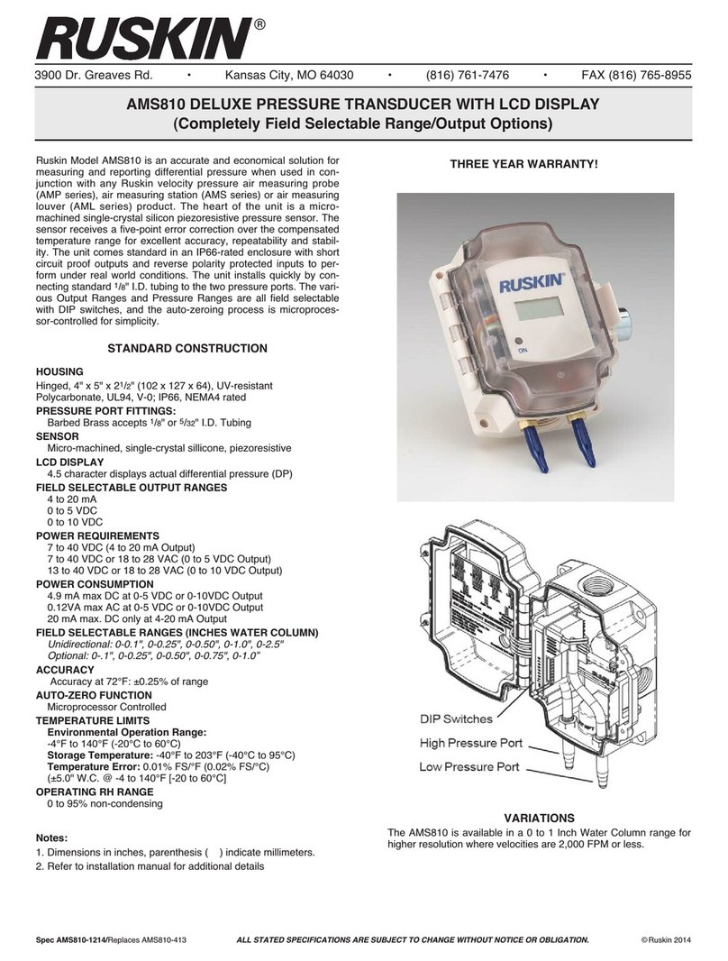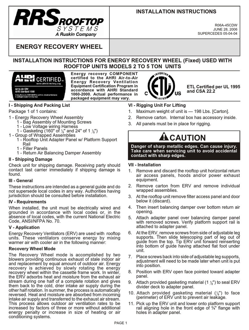
TDP05K Advanced Thermal Dispersion Probe Airow Measuring System Installation Instructions
5
TDP05K Advanced Thermal Dispersion Probe Airow Measuring System Installation Instructions
5
Table 1: Number of Probes/Sensors per Probe for Rectangular Duct Applications
Duct
Height, in.
(mm)
Duct Width, in. (mm)
12
(305)
14
(356)
16
(406)
18
(457)
20
(508)
22
(559)
24
(610)
30
(762)
36
(914)
42
(1,067)
48
(1,219)
54
(1,372)
60
(1,524)
66
(1,676)
72
(1,829)
84
(2,134)
96
(2,438)
108
(2,743)
120
(3,048)
12 (305) 1/2 1/4 1/4 1/4 1/4 1/4 1/4 1/6 1/6 1/6 1/6 1/8 1/8 1/8 1/8 1/8 1/8 1/8 1/8
14 (356) 1/4 1/4 1/4 1/4 1/4 1/6 1/6 1/6 1/6 1/8 1/8 1/8 1/8 1/8 1/8 1/8 1/8 1/8 1/8
16 (406) 2/2 2/2 2/2 2/2 2/3 2/3 2/3 1/6 1/6 1/8 1/8 1/8 1/8 1/8 1/8 1/8 1/8 1/8 1/8
18 (457) 2/2 2/2 2/2 2/2 2/3 2/3 2/2 2/2 1/8 1/8 1/8 1/8 1/8 1/8 1/8 1/8 1/8 1/8 1/8
20 (508) 2/2 2/2 2/3 2/3 2/3 2/3 2/3 2/4 1/8 1/8 1/8 1/8 2/6 2/6 2/6 2/6 2/7 2/8 1/8
22 (559) 2/2 3/2 2/3 2/3 2/3 2/3 2/3 2/4 1/8 1/8 1/8 2/6 2/6 2/6 2/6 2/7 2/8 2/8 2/8
24 (610) 2/2 3/2 2/3 2/3 2/3 2/3 2/3 2/4 2/4 1/8 1/8 2/6 2/6 2/6 2/6 2/7 2/8 2/8 2/8
30 (762) 3/2 3/2 3/2 3/2 2/4 2/4 2/4 2/4 2/4 2/6 2/6 2/6 2/7 2/7 2/8 2/8 2/8 2/8 2/8
36 (914) 3/2 3/2 3/2 4/2 4/2 4/2 2/4 2/4 2/6 2/6 2/6 2/7 2/8 2/8 2/8 2/8 2/8 2/8 2/8
42 (1,067) 3/2 4/2 4/2 4/2 4/2 4/2 4/2 2/6 2/6 2/7 2/7 2/8 2/8 2/8 2/8 2/8 2/8 2/8 2/8
48 (1,219) 3/2 4/2 4/2 4/2 4/2 4/2 4/2 3/4 2/6 2/7 2/8 2/8 2/8 2/8 2/8 2/8 2/8 2/8 2/8
54 (1,372) 4/2 4/2 4/2 4/2 4/2 3/4 3/4 3/4 2/7 2/8 2/8 2/8 2/8 2/8 4/4 2/8 2/8 2/8 2/8
60 (1,524) 4/2 4/2 4/2 4/2 3/4 3/4 3/4 4/4 4/4 2/8 2/8 2/8 4/4 4/4 4/4 4/4 2/8 2/8 2/8
66 (1,676) 4/2 4/2 4/2 4/3 3/4 3/4 3/4 4/4 4/4 4/4 2/8 2/8 4/4 4/4 4/4 4/4 4/4 2/8 2/8
72 (1,829) 4/2 4/2 4/2 4/3 3/4 3/4 3/4 4/4 4/4 4/4 2/8 4/4 4/4 4/4 4/4 4/4 4/4 4/4 2/8
84 (2,134) 4/2 4/2 4/2 4/3 3/4 4/4 4/4 4/4 4/4 4/4 4/4 4/4 4/4 4/4 4/4 4/4 4/4 4/4 4/4
96 (2,438) 4/2 4/2 4/2 4/3 4/4 4/4 4/4 4/4 4/4 4/4 4/4 4/4 4/4 4/4 4/4 4/4 4/4 4/4 4/4
108 (2,743) 4/2 4/2 4/2 4/3 4/4 4/4 4/4 4/4 4/4 4/4 4/4 4/4 4/4 4/4 4/4 4/4 4/4 4/4 4/4
120 (3,048)4/2 4/2 4/2 4/3 4/4 4/4 4/4 4/4 4/4 4/4 4/4 4/4 4/4 4/4 4/4 4/4 4/4 4/4 4/4
1. The minimum diameter size is 12 x 6.5 inches (304 x 165 mm) for rectangular duct applications. Smaller sizes can be special
ordered. For sizes less than 12 x 6.5 inches (304 x 165 mm), use the same number of probes and sensors as the 12 x 12 in.
(304 x 304 mm) size.
Table 1: Number of Probes/Sensors per Probe for Rectangular Duct Applications1
Duct
Height, in.
(mm)
Duct Width, in. (mm)
12
(305)
14
(356)
16
(406)
18
(457)
20
(508)
22
(559)
24
(610)
30
(762)
36
(914)
42
(1,067)
48
(1,219)
54
(1,372)
60
(1,524)
66
(1,676)
72
(1,829)
84
(2,134)
96
(2,438)
108
(2,743)
120
(3,048)
12 (305) 1/2 1/4 1/4 1/4 1/4 1/4 1/4 1/6 1/6 1/6 1/6 1/8 1/8 1/8 1/8 1/8 1/8 1/8 1/8
14 (356) 1/4 1/4 1/4 1/4 1/4 1/6 1/6 1/6 1/6 1/8 1/8 1/8 1/8 1/8 1/8 1/8 1/8 1/8 1/8
16 (406) 2/2 2/2 2/2 2/2 2/3 2/3 2/3 1/6 1/6 1/8 1/8 1/8 1/8 1/8 1/8 1/8 1/8 1/8 1/8
18 (457) 2/2 2/2 2/2 2/2 2/3 2/3 2/2 2/2 1/8 1/8 1/8 1/8 1/8 1/8 1/8 1/8 1/8 1/8 1/8
20 (508) 2/2 2/2 2/3 2/3 2/3 2/3 2/3 2/4 1/8 1/8 1/8 1/8 2/6 2/6 2/6 2/6 2/7 2/8 1/8
22 (559) 2/2 3/2 2/3 2/3 2/3 2/3 2/3 2/4 1/8 1/8 1/8 2/6 2/6 2/6 2/6 2/7 2/8 2/8 2/8
24 (610) 2/2 3/2 2/3 2/3 2/3 2/3 2/3 2/4 2/4 1/8 1/8 2/6 2/6 2/6 2/6 2/7 2/8 2/8 2/8
30 (762) 3/2 3/2 3/2 3/2 2/4 2/4 2/4 2/4 2/4 2/6 2/6 2/6 2/7 2/7 2/8 2/8 2/8 2/8 2/8
36 (914) 3/2 3/2 3/2 4/2 4/2 4/2 2/4 2/4 2/6 2/6 2/6 2/7 2/8 2/8 2/8 2/8 2/8 2/8 2/8
42 (1,067) 3/2 4/2 4/2 4/2 4/2 4/2 4/2 2/6 2/6 2/7 2/7 2/8 2/8 2/8 2/8 2/8 2/8 2/8 2/8
48 (1,219) 3/2 4/2 4/2 4/2 4/2 4/2 4/2 3/4 2/6 2/7 2/8 2/8 2/8 2/8 2/8 2/8 2/8 2/8 2/8
54 (1,372) 4/2 4/2 4/2 4/2 4/2 3/4 3/4 3/4 2/7 2/8 2/8 2/8 2/8 2/8 4/4 2/8 2/8 2/8 2/8
60 (1,524) 4/2 4/2 4/2 4/2 3/4 3/4 3/4 4/4 4/4 2/8 2/8 2/8 4/4 4/4 4/4 4/4 2/8 2/8 2/8
66 (1,676) 4/2 4/2 4/2 4/3 3/4 3/4 3/4 4/4 4/4 4/4 2/8 2/8 4/4 4/4 4/4 4/4 4/4 2/8 2/8
72 (1,829) 4/2 4/2 4/2 4/3 3/4 3/4 3/4 4/4 4/4 4/4 2/8 4/4 4/4 4/4 4/4 4/4 4/4 4/4 2/8
84 (2,134) 4/2 4/2 4/2 4/3 3/4 4/4 4/4 4/4 4/4 4/4 4/4 4/4 4/4 4/4 4/4 4/4 4/4 4/4 4/4
96 (2,438) 4/2 4/2 4/2 4/3 4/4 4/4 4/4 4/4 4/4 4/4 4/4 4/4 4/4 4/4 4/4 4/4 4/4 4/4 4/4
108 (2,743) 4/2 4/2 4/2 4/3 4/4 4/4 4/4 4/4 4/4 4/4 4/4 4/4 4/4 4/4 4/4 4/4 4/4 4/4 4/4
120 (3,048)4/2 4/2 4/2 4/3 4/4 4/4 4/4 4/4 4/4 4/4 4/4 4/4 4/4 4/4 4/4 4/4 4/4 4/4 4/4
1. The minimum diameter size is 12 x 6.5 inches (304 x 165 mm) for rectangular duct applications. Smaller sizes can be special
ordered. For sizes less than 12 x 6.5 inches (304 x 165 mm), use the same number of probes and sensors as the 12 x 12 in.
(304 x 304 mm) size.
HIGHEST SENSOR DENSITY PERSQUAREFOOT INTHEINDUSTRY
DETAILA
Probe/sensor placement for rectangular applications
12" 14" 16" 18" 20" 22" 24" 30" 36" 42" 48" 54" 60" 66" 72" 84" 96" 108" 120"
(305) (356) (406) (457) (508) (559) (610) (762) (914) (1067)(1219)(1372)(1524)(1676)(1829)(2134)(2438)(2743)
(3048)
12" (305)
1/2 1/4 1/4 1/4 1/4 1/4 1/4 1/6 1/6 1/6 1/6 1/8 1/8 1/8 1/8 1/8 1/8 1/8 1/8
14" (356)
1/4 1/4 1/4 1/4 1/4 1/6 1/6 1/6 1/6 1/8 1/8 1/8 1/8 1/8 1/8 1/8 1/8 1/8 1/8
16"(406)
2/2 2/2 2/2 2/2 2/3 2/3 2/3 1/6 1/6 1/8 1/8 1/8 1/8 1/8 1/8 1/8 1/8 1/8 1/8
18" (457)
2/2 2/2 2/2 2/3 2/3 2/3 2/3 1/6 1/8 1/8 1/8 1/8 1/8 1/8 1/8 1/8 1/8 1/8 1/8
20" (508)
2/2 2/2 2/3 2/3 2/3 2/3 2/3 2/4 1/8 1/8 1/8 1/8 2/6 2/6 2/6 2/6 2/7 2/8 1/8
22"(559)
2/2 3/2 2/3 2/3 2/3 2/3 2/3 2/4 1/8 1/8 1/8 2/6 2/6 2/6 2/6 2/7 2/8 2/8 2/8
24" (610)
2/2 3/2 2/3 2/3 2/3 2/3 2/3 2/4 2/4 1/8 1/8 2/6 2/6 2/6 2/6 2/7 2/8 2/8 2/8
30" (762)
3/2 3/2 3/2 3/2 2/4 2/4 2/4 2/4 2/4 2/6 2/6 2/6 2/7 2/7 2/8 2/8 2/8 2/8 2/8
36" (914)
3/2 3/2 3/2 4/2 4/2 4/2 2/4 2/4 2/6 2/6 2/6 2/7 2/8 2/8 2/8 2/8 2/8 2/8 2/8
42" (1067)
3/2 4/2 4/2 4/2 4/2 4/2 4/2 2/6 2/6 2/7 2/7 2/8 2/8 2/8 2/8 2/8 2/8 2/8 2/8
48" (1219)
3/2 4/2 4/2 4/2 4/2 4/2 4/2 3/4 2/6 2/7 2/8 2/8 2/8 2/8 2/8 2/8 2/8 2/8 2/8
54" (1372)
4/2 4/2 4/2 4/2 4/2 3/4 3/4 3/4 2/7 2/8 2/8 2/8 2/8 2/8 4/4 2/8 2/8 2/8 2/8
60" (1524)
4/2 4/2 4/2 4/2 3/4 3/4 3/4 4/4 4/4 2/8 2/8 2/8 4/4 4/4 4/4 4/4 2/8 2/8 2/8
66" (1676)
4/2 4/2 4/2 4/3 3/4 3/4 3/4 4/4 4/4 4/4 2/8 2/8 4/4 4/4 4/4 4/4 4/4 2/8 2/8
72" (1829)
4/2 4/2 4/2 4/3 3/4 3/4 3/4 4/4 4/4 4/4 2/8 4/4 4/4 4/4 4/4 4/4 4/4 4/4 2/8
84" (2134)
4/2 4/2 4/2 4/3 3/4 4/4 4/4 4/4 4/4 4/4 4/4 4/4 4/4 4/4 4/4 4/4 4/4 4/4 4/4
96" (2438)
4/2 4/2 4/2 4/3 4/4 4/4 4/4 4/4 4/4 4/4 4/4 4/4 4/4 4/4 4/4 4/4 4/4 4/4 4/4
108" (2743)
4/2 4/2 4/2 4/3 4/4 4/4 4/4 4/4 4/4 4/4 4/4 4/4 4/4 4/4 4/4 4/4 4/4 4/4 4/4
120" (3048)
4/2 4/2 4/2 4/3 4/4 4/4 4/4 4/4 4/4 4/4 4/4 4/4 4/4 4/4 4/4 4/4 4/4 4/4 4/4
Duct Height
"B"
Duct Width A - Probe Length
The model TDP05K probe assembly may be installed in square,
round, or oval ducts and plenums. Hardware required for the insertion
style mounting configuration (as depicted in the DETAILS shown
below) is provided as standard with the TDP05K. Stand-off mounting
hardware is available as an option for applications that require probes
mounted onto the upstream side of a Ruskin model CD50, CD60 or
insulated TED50 control damper (damper sold separately). For
specific installation and operation details, and for round or oval
applications, refer to the Installation and Maintenance Instructions.
The information on this data sheet is for general reference and is
subject to correction or modification.
DETAIL 3
DETAIL 2
DETAIL 4
Primary
Probe
Ancillary
Probe
Duct Height
Height / 2
Height / 4
Duct Height
Height / 2
Duct Width
Duct Width
Primary
Probe
Ancillary
Probe
Ancillary
Probe
Ancillary
Probe
Primary
Probe
Ancillary
Probe
Ancillary
Probe
Duct
Height
Height / 3
Height / 3
Height / 6
Duct
Height
Height / 4
Height / 4
Height / 4
Height / 8
Duct Width
Duct Width
DETAIL 1
Round Duct Mounting
Attach Round Duct Hinge Plate to Round Duct Mounting Plate.
5
Rectangular Duct Internal Mounting
Each Internal Mount Air Measurement System consists of one or more ancillary probes to be mounted inside existing
ductwork or opening to be wired to an externally located REMOTE WIRED PRIMARY or junction box. The REMOTE
WIRED PRIMARY receives air and temperature measurement data via the probe network’s twisted shielded pair. The
REMOTE WIRED PRIMARY is the user interface as well as the interface point for power and connection to the Building
Automation System. Spacing of Internal mount probes is the same as Insertion mount probes.
FRONTVIEW
Install with sensors on bottom of probe when installed horizontally.
6.52
REF.
ACTUAL DUCT SIZE MINUS 1/2”
14", 18", 24", 30" or 36"
Sensing Points
3.80
REF.
DIMENSION
14
18
24
30
36
Probe/Sensor Count per Duct Size
#Probes / #Sensors per Probe
Example: HTDP-S ordered for a 24"w x 24"h
duct will consist of two (2) 24" long probes
with each probe having 4 sensors (2/4)
Typical HTDP-S Installation Configuration
(HTDP-S shown with 3 duct-mounted ancillary probes wired to
wall-mounted Remote Primary Controller with Display)
Model HTDP-S
AVAILABLE FOR
NEXT-DAY OR SAME-DAY
SHIPPING!
TDP05K Advanced Thermal Dispersion Probe Airow Measuring System Installation Instructions
5
Table 1: Number of Probes/Sensors per Probe for Rectangular Duct Applications1
Duct
Height, in.
(mm)
Duct Width, in. (mm)
12
(305)
14
(356)
16
(406)
18
(457)
20
(508)
22
(559)
24
(610)
30
(762)
36
(914)
42
(1,067)
48
(1,219)
54
(1,372)
60
(1,524)
66
(1,676)
72
(1,829)
84
(2,134)
96
(2,438)
108
(2,743)
120
(3,048)
12 (305) 1/2 1/4 1/4 1/4 1/4 1/4 1/4 1/6 1/6 1/6 1/6 1/8 1/8 1/8 1/8 1/8 1/8 1/8 1/8
14 (356) 1/4 1/4 1/4 1/4 1/4 1/6 1/6 1/6 1/6 1/8 1/8 1/8 1/8 1/8 1/8 1/8 1/8 1/8 1/8
16 (406) 2/2 2/2 2/2 2/2 2/3 2/3 2/3 1/6 1/6 1/8 1/8 1/8 1/8 1/8 1/8 1/8 1/8 1/8 1/8
18 (457) 2/2 2/2 2/2 2/2 2/3 2/3 2/2 2/2 1/8 1/8 1/8 1/8 1/8 1/8 1/8 1/8 1/8 1/8 1/8
20 (508) 2/2 2/2 2/3 2/3 2/3 2/3 2/3 2/4 1/8 1/8 1/8 1/8 2/6 2/6 2/6 2/6 2/7 2/8 1/8
22 (559) 2/2 3/2 2/3 2/3 2/3 2/3 2/3 2/4 1/8 1/8 1/8 2/6 2/6 2/6 2/6 2/7 2/8 2/8 2/8
24 (610) 2/2 3/2 2/3 2/3 2/3 2/3 2/3 2/4 2/4 1/8 1/8 2/6 2/6 2/6 2/6 2/7 2/8 2/8 2/8
30 (762) 3/2 3/2 3/2 3/2 2/4 2/4 2/4 2/4 2/4 2/6 2/6 2/6 2/7 2/7 2/8 2/8 2/8 2/8 2/8
36 (914) 3/2 3/2 3/2 4/2 4/2 4/2 2/4 2/4 2/6 2/6 2/6 2/7 2/8 2/8 2/8 2/8 2/8 2/8 2/8
42 (1,067) 3/2 4/2 4/2 4/2 4/2 4/2 4/2 2/6 2/6 2/7 2/7 2/8 2/8 2/8 2/8 2/8 2/8 2/8 2/8
48 (1,219) 3/2 4/2 4/2 4/2 4/2 4/2 4/2 3/4 2/6 2/7 2/8 2/8 2/8 2/8 2/8 2/8 2/8 2/8 2/8
54 (1,372) 4/2 4/2 4/2 4/2 4/2 3/4 3/4 3/4 2/7 2/8 2/8 2/8 2/8 2/8 4/4 2/8 2/8 2/8 2/8
60 (1,524) 4/2 4/2 4/2 4/2 3/4 3/4 3/4 4/4 4/4 2/8 2/8 2/8 4/4 4/4 4/4 4/4 2/8 2/8 2/8
66 (1,676) 4/2 4/2 4/2 4/3 3/4 3/4 3/4 4/4 4/4 4/4 2/8 2/8 4/4 4/4 4/4 4/4 4/4 2/8 2/8
72 (1,829) 4/2 4/2 4/2 4/3 3/4 3/4 3/4 4/4 4/4 4/4 2/8 4/4 4/4 4/4 4/4 4/4 4/4 4/4 2/8
84 (2,134) 4/2 4/2 4/2 4/3 3/4 4/4 4/4 4/4 4/4 4/4 4/4 4/4 4/4 4/4 4/4 4/4 4/4 4/4 4/4
96 (2,438) 4/2 4/2 4/2 4/3 4/4 4/4 4/4 4/4 4/4 4/4 4/4 4/4 4/4 4/4 4/4 4/4 4/4 4/4 4/4
108 (2,743) 4/2 4/2 4/2 4/3 4/4 4/4 4/4 4/4 4/4 4/4 4/4 4/4 4/4 4/4 4/4 4/4 4/4 4/4 4/4
120 (3,048)4/2 4/2 4/2 4/3 4/4 4/4 4/4 4/4 4/4 4/4 4/4 4/4 4/4 4/4 4/4 4/4 4/4 4/4 4/4
1. The minimum diameter size is 12 x 6.5 inches (304 x 165 mm) for rectangular duct applications. Smaller sizes can be special
ordered. For sizes less than 12 x 6.5 inches (304 x 165 mm), use the same number of probes and sensors as the 12 x 12 in.
(304 x 304 mm) size.
TDP05K Advanced Thermal Dispersion Probe Airow Measuring System Installation Instructions
5
Table 1: Number of Probes/Sensors per Probe for Rectangular Duct Applications
Duct
Height, in.
(mm)
Duct Width, in. (mm)
12
(305)
14
(356)
16
(406)
18
(457)
20
(508)
22
(559)
24
(610)
30
(762)
36
(914)
42
(1,067)
48
(1,219)
54
(1,372)
60
(1,524)
66
(1,676)
72
(1,829)
84
(2,134)
96
(2,438)
108
(2,743)
120
(3,048)
12 (305) 1/2 1/4 1/4 1/4 1/4 1/4 1/4 1/6 1/6 1/6 1/6 1/8 1/8 1/8 1/8 1/8 1/8 1/8 1/8
14 (356) 1/4 1/4 1/4 1/4 1/4 1/6 1/6 1/6 1/6 1/8 1/8 1/8 1/8 1/8 1/8 1/8 1/8 1/8 1/8
16 (406) 2/2 2/2 2/2 2/2 2/3 2/3 2/3 1/6 1/6 1/8 1/8 1/8 1/8 1/8 1/8 1/8 1/8 1/8 1/8
18 (457) 2/2 2/2 2/2 2/2 2/3 2/3 2/2 2/2 1/8 1/8 1/8 1/8 1/8 1/8 1/8 1/8 1/8 1/8 1/8
20 (508) 2/2 2/2 2/3 2/3 2/3 2/3 2/3 2/4 1/8 1/8 1/8 1/8 2/6 2/6 2/6 2/6 2/7 2/8 1/8
22 (559) 2/2 3/2 2/3 2/3 2/3 2/3 2/3 2/4 1/8 1/8 1/8 2/6 2/6 2/6 2/6 2/7 2/8 2/8 2/8
24 (610) 2/2 3/2 2/3 2/3 2/3 2/3 2/3 2/4 2/4 1/8 1/8 2/6 2/6 2/6 2/6 2/7 2/8 2/8 2/8
30 (762) 3/2 3/2 3/2 3/2 2/4 2/4 2/4 2/4 2/4 2/6 2/6 2/6 2/7 2/7 2/8 2/8 2/8 2/8 2/8
36 (914) 3/2 3/2 3/2 4/2 4/2 4/2 2/4 2/4 2/6 2/6 2/6 2/7 2/8 2/8 2/8 2/8 2/8 2/8 2/8
42 (1,067) 3/2 4/2 4/2 4/2 4/2 4/2 4/2 2/6 2/6 2/7 2/7 2/8 2/8 2/8 2/8 2/8 2/8 2/8 2/8
48 (1,219) 3/2 4/2 4/2 4/2 4/2 4/2 4/2 3/4 2/6 2/7 2/8 2/8 2/8 2/8 2/8 2/8 2/8 2/8 2/8
54 (1,372) 4/2 4/2 4/2 4/2 4/2 3/4 3/4 3/4 2/7 2/8 2/8 2/8 2/8 2/8 4/4 2/8 2/8 2/8 2/8
60 (1,524) 4/2 4/2 4/2 4/2 3/4 3/4 3/4 4/4 4/4 2/8 2/8 2/8 4/4 4/4 4/4 4/4 2/8 2/8 2/8
66 (1,676) 4/2 4/2 4/2 4/3 3/4 3/4 3/4 4/4 4/4 4/4 2/8 2/8 4/4 4/4 4/4 4/4 4/4 2/8 2/8
72 (1,829) 4/2 4/2 4/2 4/3 3/4 3/4 3/4 4/4 4/4 4/4 2/8 4/4 4/4 4/4 4/4 4/4 4/4 4/4 2/8
84 (2,134) 4/2 4/2 4/2 4/3 3/4 4/4 4/4 4/4 4/4 4/4 4/4 4/4 4/4 4/4 4/4 4/4 4/4 4/4 4/4
96 (2,438) 4/2 4/2 4/2 4/3 4/4 4/4 4/4 4/4 4/4 4/4 4/4 4/4 4/4 4/4 4/4 4/4 4/4 4/4 4/4
108 (2,743) 4/2 4/2 4/2 4/3 4/4 4/4 4/4 4/4 4/4 4/4 4/4 4/4 4/4 4/4 4/4 4/4 4/4 4/4 4/4
120 (3,048)4/2 4/2 4/2 4/3 4/4 4/4 4/4 4/4 4/4 4/4 4/4 4/4 4/4 4/4 4/4 4/4 4/4 4/4 4/4
1. The minimum diameter size is 12 x 6.5 inches (304 x 165 mm) for rectangular duct applications. Smaller sizes can be special
ordered. For sizes less than 12 x 6.5 inches (304 x 165 mm), use the same number of probes and sensors as the 12 x 12 in.
(304 x 304 mm) size.
Table 1: Number of Probes/Sensors per Probe for Rectangular Duct Applications1
Duct
Height, in.
(mm)
Duct Width, in. (mm)
12
(305)
14
(356)
16
(406)
18
(457)
20
(508)
22
(559)
24
(610)
30
(762)
36
(914)
42
(1,067)
48
(1,219)
54
(1,372)
60
(1,524)
66
(1,676)
72
(1,829)
84
(2,134)
96
(2,438)
108
(2,743)
120
(3,048)
12 (305) 1/2 1/4 1/4 1/4 1/4 1/4 1/4 1/6 1/6 1/6 1/6 1/8 1/8 1/8 1/8 1/8 1/8 1/8 1/8
14 (356) 1/4 1/4 1/4 1/4 1/4 1/6 1/6 1/6 1/6 1/8 1/8 1/8 1/8 1/8 1/8 1/8 1/8 1/8 1/8
16 (406) 2/2 2/2 2/2 2/2 2/3 2/3 2/3 1/6 1/6 1/8 1/8 1/8 1/8 1/8 1/8 1/8 1/8 1/8 1/8
18 (457) 2/2 2/2 2/2 2/2 2/3 2/3 2/2 2/2 1/8 1/8 1/8 1/8 1/8 1/8 1/8 1/8 1/8 1/8 1/8
20 (508) 2/2 2/2 2/3 2/3 2/3 2/3 2/3 2/4 1/8 1/8 1/8 1/8 2/6 2/6 2/6 2/6 2/7 2/8 1/8
22 (559) 2/2 3/2 2/3 2/3 2/3 2/3 2/3 2/4 1/8 1/8 1/8 2/6 2/6 2/6 2/6 2/7 2/8 2/8 2/8
24 (610) 2/2 3/2 2/3 2/3 2/3 2/3 2/3 2/4 2/4 1/8 1/8 2/6 2/6 2/6 2/6 2/7 2/8 2/8 2/8
30 (762) 3/2 3/2 3/2 3/2 2/4 2/4 2/4 2/4 2/4 2/6 2/6 2/6 2/7 2/7 2/8 2/8 2/8 2/8 2/8
36 (914) 3/2 3/2 3/2 4/2 4/2 4/2 2/4 2/4 2/6 2/6 2/6 2/7 2/8 2/8 2/8 2/8 2/8 2/8 2/8
42 (1,067) 3/2 4/2 4/2 4/2 4/2 4/2 4/2 2/6 2/6 2/7 2/7 2/8 2/8 2/8 2/8 2/8 2/8 2/8 2/8
48 (1,219) 3/2 4/2 4/2 4/2 4/2 4/2 4/2 3/4 2/6 2/7 2/8 2/8 2/8 2/8 2/8 2/8 2/8 2/8 2/8
54 (1,372) 4/2 4/2 4/2 4/2 4/2 3/4 3/4 3/4 2/7 2/8 2/8 2/8 2/8 2/8 4/4 2/8 2/8 2/8 2/8
60 (1,524) 4/2 4/2 4/2 4/2 3/4 3/4 3/4 4/4 4/4 2/8 2/8 2/8 4/4 4/4 4/4 4/4 2/8 2/8 2/8
66 (1,676) 4/2 4/2 4/2 4/3 3/4 3/4 3/4 4/4 4/4 4/4 2/8 2/8 4/4 4/4 4/4 4/4 4/4 2/8 2/8
72 (1,829) 4/2 4/2 4/2 4/3 3/4 3/4 3/4 4/4 4/4 4/4 2/8 4/4 4/4 4/4 4/4 4/4 4/4 4/4 2/8
84 (2,134) 4/2 4/2 4/2 4/3 3/4 4/4 4/4 4/4 4/4 4/4 4/4 4/4 4/4 4/4 4/4 4/4 4/4 4/4 4/4
96 (2,438) 4/2 4/2 4/2 4/3 4/4 4/4 4/4 4/4 4/4 4/4 4/4 4/4 4/4 4/4 4/4 4/4 4/4 4/4 4/4
108 (2,743) 4/2 4/2 4/2 4/3 4/4 4/4 4/4 4/4 4/4 4/4 4/4 4/4 4/4 4/4 4/4 4/4 4/4 4/4 4/4
120 (3,048)4/2 4/2 4/2 4/3 4/4 4/4 4/4 4/4 4/4 4/4 4/4 4/4 4/4 4/4 4/4 4/4 4/4 4/4 4/4
1. The minimum diameter size is 12 x 6.5 inches (304 x 165 mm) for rectangular duct applications. Smaller sizes can be special
ordered. For sizes less than 12 x 6.5 inches (304 x 165 mm), use the same number of probes and sensors as the 12 x 12 in.
(304 x 304 mm) size.
HIGHEST SENSOR DENSITY PERSQUAREFOOT INTHEINDUSTRY
DETAILA
Probe/sensor placement for rectangular applications
12" 14" 16" 18" 20" 22" 24" 30" 36" 42" 48" 54" 60" 66" 72" 84" 96" 108" 120"
(305) (356) (406) (457) (508) (559) (610) (762) (914) (1067)(1219)(1372)(1524)(1676)(1829)(2134)(2438)(2743)
(3048)
12" (305)
1/2 1/4 1/4 1/4 1/4 1/4 1/4 1/6 1/6 1/6 1/6 1/8 1/8 1/8 1/8 1/8 1/8 1/8 1/8
14" (356)
1/4 1/4 1/4 1/4 1/4 1/6 1/6 1/6 1/6 1/8 1/8 1/8 1/8 1/8 1/8 1/8 1/8 1/8 1/8
16"(406)
2/2 2/2 2/2 2/2 2/3 2/3 2/3 1/6 1/6 1/8 1/8 1/8 1/8 1/8 1/8 1/8 1/8 1/8 1/8
18" (457)
2/2 2/2 2/2 2/3 2/3 2/3 2/3 1/6 1/8 1/8 1/8 1/8 1/8 1/8 1/8 1/8 1/8 1/8 1/8
20" (508)
2/2 2/2 2/3 2/3 2/3 2/3 2/3 2/4 1/8 1/8 1/8 1/8 2/6 2/6 2/6 2/6 2/7 2/8 1/8
22"(559)
2/2 3/2 2/3 2/3 2/3 2/3 2/3 2/4 1/8 1/8 1/8 2/6 2/6 2/6 2/6 2/7 2/8 2/8 2/8
24" (610)
2/2 3/2 2/3 2/3 2/3 2/3 2/3 2/4 2/4 1/8 1/8 2/6 2/6 2/6 2/6 2/7 2/8 2/8 2/8
30" (762)
3/2 3/2 3/2 3/2 2/4 2/4 2/4 2/4 2/4 2/6 2/6 2/6 2/7 2/7 2/8 2/8 2/8 2/8 2/8
36" (914)
3/2 3/2 3/2 4/2 4/2 4/2 2/4 2/4 2/6 2/6 2/6 2/7 2/8 2/8 2/8 2/8 2/8 2/8 2/8
42" (1067)
3/2 4/2 4/2 4/2 4/2 4/2 4/2 2/6 2/6 2/7 2/7 2/8 2/8 2/8 2/8 2/8 2/8 2/8 2/8
48" (1219)
3/2 4/2 4/2 4/2 4/2 4/2 4/2 3/4 2/6 2/7 2/8 2/8 2/8 2/8 2/8 2/8 2/8 2/8 2/8
54" (1372)
4/2 4/2 4/2 4/2 4/2 3/4 3/4 3/4 2/7 2/8 2/8 2/8 2/8 2/8 4/4 2/8 2/8 2/8 2/8
60" (1524)
4/2 4/2 4/2 4/2 3/4 3/4 3/4 4/4 4/4 2/8 2/8 2/8 4/4 4/4 4/4 4/4 2/8 2/8 2/8
66" (1676)
4/2 4/2 4/2 4/3 3/4 3/4 3/4 4/4 4/4 4/4 2/8 2/8 4/4 4/4 4/4 4/4 4/4 2/8 2/8
72" (1829)
4/2 4/2 4/2 4/3 3/4 3/4 3/4 4/4 4/4 4/4 2/8 4/4 4/4 4/4 4/4 4/4 4/4 4/4 2/8
84" (2134)
4/2 4/2 4/2 4/3 3/4 4/4 4/4 4/4 4/4 4/4 4/4 4/4 4/4 4/4 4/4 4/4 4/4 4/4 4/4
96" (2438)
4/2 4/2 4/2 4/3 4/4 4/4 4/4 4/4 4/4 4/4 4/4 4/4 4/4 4/4 4/4 4/4 4/4 4/4 4/4
108" (2743)
4/2 4/2 4/2 4/3 4/4 4/4 4/4 4/4 4/4 4/4 4/4 4/4 4/4 4/4 4/4 4/4 4/4 4/4 4/4
120" (3048)
4/2 4/2 4/2 4/3 4/4 4/4 4/4 4/4 4/4 4/4 4/4 4/4 4/4 4/4 4/4 4/4 4/4 4/4 4/4
Duct Height
"B"
Duct Width A - Probe Length
The model TDP05K probe assembly may be installed in square,
round, or oval ducts and plenums. Hardware required for the insertion
style mounting configuration (as depicted in the DETAILS shown
below) is provided as standard with the TDP05K. Stand-off mounting
hardware is available as an option for applications that require probes
mounted onto the upstream side of a Ruskin model CD50, CD60 or
insulated TED50 control damper (damper sold separately). For
specific installation and operation details, and for round or oval
applications, refer to the Installation and Maintenance Instructions.
The information on this data sheet is for general reference and is
subject to correction or modification.
DETAIL 3
DETAIL 2
DETAIL 4
Primary
Probe
Ancillary
Probe
Duct Height
Height / 2
Height / 4
Duct Height
Height / 2
Duct Width
Duct Width
Primary
Probe
Ancillary
Probe
Ancillary
Probe
Ancillary
Probe
Primary
Probe
Ancillary
Probe
Ancillary
Probe
Duct
Height
Height / 3
Height / 3
Height / 6
Duct
Height
Height / 4
Height / 4
Height / 4
Height / 8
Duct Width
Duct Width
DETAIL 1
Round Duct Mounting
Attach Round Duct Hinge Plate to Round Duct Mounting Plate.
5
Round Duct Mounting
Attach Round Duct Hinge Plate to Round Duct Mounting Plate.
Table 1: Number of Probes / Sensors per Probe for Rectangular Duct Applications
Table 1: Number of Probes / Sensors per Probe for Rectangular Duct Applications
Table 1: Number of Probes / Sensors per Probe for Rectangular Duct Applications
Table 1: Number of Probes / Sensors per Probe for Rectangular Duct Applications
Table 1: Number of Probes / Sensors per Probe for Rectangular Duct Applications
Table 1: Number of Probes / Sensors per Probe for Rectangular Duct Applications
Table 1: Number of Probes / Sensors per Probe for Rectangular Duct Applications
Table 1: Number of Probes / Sensors per Probe for Rectangular Duct Applications
Table 1: Number of Probes / Sensors per Probe for Rectangular Duct Applications
Table 1: Number of Probes / Sensors per Probe for Rectangular Duct Applications
Table 1: Number of Probes / Sensors per Probe for Rectangular Duct Applications
Table 1: Number of Probes / Sensors per Probe for Rectangular Duct Applications
Table 1: Number of Probes / Sensors per Probe for Rectangular Duct Applications
Table 1: Number of Probes / Sensors per Probe for Rectangular Duct Applications
Table 1: Number of Probes / Sensors per Probe for Rectangular Duct Applications
Table 1: Number of Probes / Sensors per Probe for Rectangular Duct Applications
Table 1: Number of Probes / Sensors per Probe for Rectangular Duct Applications
Table 1: Number of Probes / Sensors per Probe for Rectangular Duct Applications
Table 1: Number of Probes / Sensors per Probe for Rectangular Duct Applications
Table 1: Number of Probes / Sensors per Probe for Rectangular Duct Applications
Table 1: Number of Probes / Sensors per Probe for Rectangular Duct Applications
Rectangular Duct Width "A" = Probe Length
Rectangular Duct Width "A" = Probe Length
Rectangular Duct Width "A" = Probe Length
Rectangular Duct Width "A" = Probe Length
Rectangular Duct Width "A" = Probe Length
Rectangular Duct Width "A" = Probe Length
Rectangular Duct Width "A" = Probe Length
Rectangular Duct Width "A" = Probe Length
Rectangular Duct Width "A" = Probe Length
Rectangular Duct Width "A" = Probe Length
Rectangular Duct Width "A" = Probe Length
Rectangular Duct Width "A" = Probe Length
Rectangular Duct Width "A" = Probe Length
Rectangular Duct Width "A" = Probe Length
Rectangular Duct Width "A" = Probe Length
Rectangular Duct Width "A" = Probe Length
Rectangular Duct Width "A" = Probe Length
Rectangular Duct Width "A" = Probe Length
Rectangular Duct Width "A" = Probe Length
Rectangular Duct Width "A" = Probe Length
8"
12"
14"
16"
18"
20"
22"
24"
30"
36"
42"
48"
54"
60"
66"
72"
84"
96"
108"
120"
Rectangular Duct Internal Mounting
Each Internal Mount Air Measurement System consists of one or more ancillary probes to be mounted inside existing
ductwork or opening to be wired to an externally located REMOTE WIRED PRIMARY or junction box. The REMOTE
WIRED PRIMARY receives air and temperature measurement data via the probe network’s twisted shielded pair. The
REMOTE WIRED PRIMARY is the user interface as well as the interface point for power and connection to the Building
Automation System. Spacing of Internal mount probes is the same as Insertion mount probes.
Rectangular Duct Width "A" = Probe Length
Rectangular Duct Width "A" = Probe Length
Rectangular Duct Width "A" = Probe Length
Rectangular Duct Width "A" = Probe Length
Rectangular Duct Width "A" = Probe Length
Rectangular Duct Width "A" = Probe Length
Rectangular Duct Width "A" = Probe Length
Rectangular Duct Width "A" = Probe Length
Rectangular Duct Width "A" = Probe Length
Rectangular Duct Width "A" = Probe Length
Rectangular Duct Width "A" = Probe Length
Rectangular Duct Width "A" = Probe Length
Rectangular Duct Width "A" = Probe Length
Rectangular Duct Width "A" = Probe Length
Rectangular Duct Width "A" = Probe Length
Rectangular Duct Width "A" = Probe Length
Rectangular Duct Width "A" = Probe Length
Rectangular Duct Width "A" = Probe Length
Rectangular Duct Width "A" = Probe Length
Rectangular Duct Width "A" = Probe Length
8"
(203)
12"
(305)
14"
(356)
16"
(406)
18"
(457)
20"
(508)
22"
(559)
24"
(610)
30"
(762)
36"
(914)
42"
(1067)
48"
(1219)
54"
(1372)
60"
(1524)
66"
(1676)
72"
(1829)
84"
(2134)
96"
(2438)
108"
(2743)
120"
(3048)
FRONT VIEW
GREATER THAN 60" AND UP TO 120"
3 PROBES WITH 8 SENSORS
SEE TABLE FOR EK MEAN DISTRIBUTION
AUTHOR BJC
CHECKED ENK
APPROVED
10/7/2015
10/20/2015
PRODUCT
SIZE
D
SCALE
DWG NO REV
C
SHEET 2 OF 2INVENTOR
MATERIAL
ECN
TITLE
3900 Doctor Greaves Rd,
Grandview, MO 64030
PROPRIETARY AND
CONFIDENTIAL
TDP05K
87-020155-00D
ROUND PROBE CONFIGURATIONS
NONE6347 8/15/2018
APPROVED
SLEEVE LENGTH
(12" MINIMUM)
PRIMARY PROBE
87-020162-03D
NOTES:
1. EQUAL AREA DISTRIBUTION SHOWN.
2. USE THIS LAYOUT FOR EK MEAN DISTRIBUTION ALSO.
3. SEE ORDER FOR DISTRIBUTION TYPE.
4. ALL DIMENSIONS GIVEN IN INCHES.
ANCILLARY PROBE
87-020162-04D
EK MEAN DISTRIBUTION
DIAMETER PROBES/SENSORS
GREATER THAN 32" & LESS THAN 48" 3/4
GREATER THAN OR EQUAL TO 48" & LESS THAN 56" 3/6
GREATER THAN OR EQUAL TO 56" 3/8
DREVISED NOTE UNDER FRONT VIEW
TO SHOW UPDATED SIZES DPM ABH 8/15/2018
C REMOVED OBSOLETE PROBE NUMBERS BJC 7/31/2017
B SEE SHEET 1 BJC LEH JDW 2/1/2017
REV DESCRIPTION BY CHK APV APVD DATE
UNLESS OTHERWISE SPECIFIED, USE STD.
ENGINEERING TOLERANCES PER WIQ-008
DRAWING NUMBER DESCRIPTION
87-020156-00D OVAL DUCT CONFIGURATION
87-020157-00D RECTANGULAR EA DUCT CONFIGURATION
87-020181-00D RECTANGULAR LOG C DUCT CONFIGURATION
10-24 x .75
SELF DRILLING SCREW
(4 REQUIRED PER CONTROL BOX)
C
C
D
SLEEVE LENGTH / 2 - 2.125
SLEEVE LENGTH / 2
SLEEVE LENGTH / 2 + 2.125
FRONT VIEW
GREATER THAN 60" AND UP TO 120"
3 PROBES WITH 8 SENSORS
SEE TABLE FOR EK MEAN DISTRIBUTION
ANCILLARY VIEW
AUTHOR BJC
CHECKED ENK
APPROVED
10/7/2015
10/20/2015
PRODUCT
SIZE
D
SCALE
DWG NO REV
C
SHEET 2 OF 2INVENTOR
MATERIAL
ECN
TITLE
3900 Doctor Greaves Rd,
Grandview, MO 64030
PROPRIETARY AND
CONFIDENTIAL
TDP05K
87-020155-00D
ROUND PROBE CONFIGURATIONS
NONE6347 8/15/2018
APPROVED
SLEEVE LENGTH
(12" MINIMUM)
60°
60°
PRIMARY PROBE
PRIMARY PROBE
87-020162-03D
NOTES:
1. EQUAL AREA DISTRIBUTION SHOWN.
2. USE THIS LAYOUT FOR EK MEAN DISTRIBUTION ALSO.
3. SEE ORDER FOR DISTRIBUTION TYPE.
4. ALL DIMENSIONS GIVEN IN INCHES.
ANCILLARY PROBE
87-020162-04D
EK MEAN DISTRIBUTION
DIAMETER PROBES/SENSORS
GREATER THAN 32" & LESS THAN 48" 3/4
GREATER THAN OR EQUAL TO 48" & LESS THAN 56" 3/6
GREATER THAN OR EQUAL TO 56" 3/8
DREVISED NOTE UNDER FRONT VIEW
TO SHOW UPDATED SIZES DPM ABH 8/15/2018
C REMOVED OBSOLETE PROBE NUMBERS BJC 7/31/2017
B SEE SHEET 1 BJC LEH JDW 2/1/2017
REV DESCRIPTION BY CHK APV APVD DATE
UNLESS OTHERWISE SPECIFIED, USE STD.
ENGINEERING TOLERANCES PER WIQ-008
DRAWING NUMBER DESCRIPTION
87-020156-00D OVAL DUCT CONFIGURATION
87-020157-00D RECTANGULAR EA DUCT CONFIGURATION
87-020181-00D RECTANGULAR LOG C DUCT CONFIGURATION
10-24 x .75
SELF DRILLING SCREW
(4 REQUIRED PER CONTROL BOX)
C
C
D
SLEEVE LENGTH / 2 - 2.125
SLEEVE LENGTH / 2
SLEEVE LENGTH / 2 + 2.125
AIR
FLOW
Round Duct Mounting Offset When mounting 2 or more probes in a round duct, they must be oset
from each other by at least 2 1/8 inches, in the direction of air ow to
avoid mechanical interference.
Ruskin model HTDP-S oers the
advanced technology available with
the model TDP05K and makes it
available in these probe lengths for
Same-Day or Next-Day shipping to
meet critical project scheduling!
DETAIL A
TDP05K probe/sensor placement for rectangular applications
HTDP-S Probe/Sensor Count per Duct Size
#Probes / #Sensors per Probe


