Ryobi RPP254FEJSO User manual

OPERATOR’S MANUAL (Original Instructions)
RPP254FEJSO
25.4cc POLE PRUNER
Important! It is essential that you read the instructions in this manual before assembling,
operating, and maintaining the product.
Subject to technical modications.

2
Safety, performance, and dependability have been given
top priority in the design of your petrol pole pruner.
INTENDED USE
The petrol pole pruner is only intended for use outdoors.
For safety reasons, the product must be adequately
controlled by using two-handed operation.
The product is designed for cutting and pruning of small
limbs and branches whose diameter is less than or equal
to the bar length, and are located high in the tree while the
operator maintains a steady footing on the ground. The
product is designed to be extended to a maximum length
of 2.7 m. Do not exceed this working length.
It is not intended to be used while climbing or as a
conventional chainsaw for close quarter limbing and
pruning of material at ground level.
Do not use the product for any other purpose.
GENERAL SAFETY WARNINGS
WARNING
For safe operation, read and understand all
instructions before using the product. Follow all
safety instructions, information on correct working
posture, the need for rest periods, and changing working
positions. Failure to follow all safety instructions listed
below, can result in serious personal injury.
READ ALL INSTRUCTIONS
■Do not allow children or untrained individuals to use
the product.
■Never let anyone use the product who has not received
adequate instructions in the product’s proper use. This
applies to rentals as well as privately owned products
and also to the power head it is attached to.
■Always wear safety glasses with side shields.
Everyday glasses have only impact resistant lenses.
They are NOT safety glasses. Following this rule will
reduce the risk of eye injury.
■Product users in some states, must comply with fire
prevention regulations. The product is equipped with
a spark arrestor; however, other user requirements
may apply. Check with your federal, state, or local
authorities.
■Wear eye, hearing, and head protection when
operating the product. Hearing protection may restrict
the operator’s ability to hear warning sounds, pay
particular attention to potential hazards around and
inside the working area.
■Wear heavy-long pants, boots, and gloves. Do not
wear loose fitting clothing, short pants, or go barefoot.
Do not wear jewellery of any kind.
■Heavy protective clothing may increase operator
fatigue, which could lead to heat stroke. During
weather that is hot and humid, heavy work should be
scheduled for early morning or late afternoon hours
when temperatures are cooler.
■Never operate the product on the operator’s left side.
■Secure long hair above shoulder level to prevent
entanglement in moving parts.
■Keep all bystanders, children, and pets at least 15 m
away. Bystanders should be encouraged to wear eye
protection. If you are approached, stop the engine and
cutting attachment. In the case of bladed units, there is
the added risk of injury to bystanders from being struck
with the moving blade in the event of a blade thrust or
other unexpected reaction of the saw.
■Do not operate the product when you are tired, ill, or
under the influence of alcohol, drugs, or medication.
■Do not operate in poor lighting. The operator needs
clear unrestricted vision to identify potential hazards.
■Keep firm footing and balance. Do not overreach.
Overreaching can result in loss of balance or exposure
to hot surfaces.
■Keep all parts of your body away from any moving
part.
■To avoid hot surfaces, never operate the product with
the bottom of the engine above waist level.
■Do not touch area around the muffler or cylinder of the
product. These parts get hot from operation. Failure
to heed this warning could result in possible serious
personal injury.
■Carry the pruner with the engine stopped, the guide
bar and saw chain to the rear, scabbard on the guide
bar and saw chain, and the muffler away from your
body.
■Always stop the engine before making any
adjustments.
■Inspect the product before each use for loose
fasteners, fuel leaks, etc. Replace any damaged parts
before use.
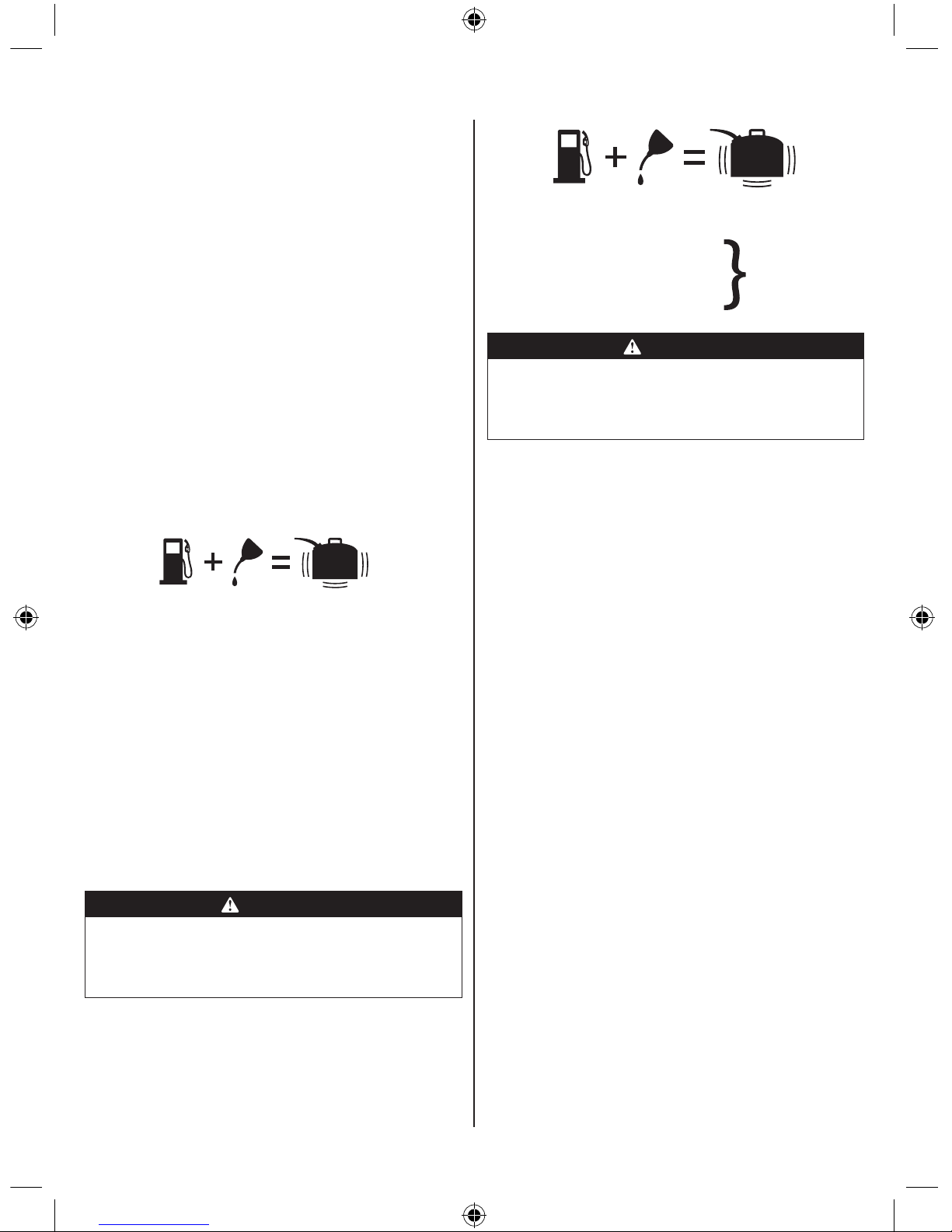
■Mix and store fuel in a container approved for petrol.
■Mix fuel outdoors where there are no sparks or flames.
Wipe up any fuel spillage. Move 9 m away from
refueling site before starting engine.
■Stop the engine and allow to cool down before
refueling or storing the product.
■Allow the engine to cool, empty the fuel tank, and
secure the product from moving before transporting in
a vehicle.
■Stop the engine. Make sure all moving parts have
come to a complete stop:
●before servicing
●before leaving the product unattended

3
●before clearing a blockage
●before checking, cleaning, and working on the
product
●before changing accessories
●after striking a foreign object
●whenever performing maintenance
●whenever the product starts to vibrate abnormally
PRUNER SAFETY WARNINGS
■Do not use the product when there is a possibility of
thunderstorm or lightning. Store the product safely
indoors.
■Ensure all guards, handles are properly fitted and are
in good condition.
■Do not start using the product until you have a clear
work area, secure footing, and a planned retreat path
away from the falling branches or limbs.
■Beware of the emission of lubricant mist and saw dust.
Wear mask or respirator if required.
■During operation, hold the product with both hands.
Use one hand to firmly grasp the front hand grip. Use
the other hand to grasp the rear handle and operate
the trigger release and engine switch.
■Cut only when visibility and light are adequate for you
to see clearly.
■Do not use on a ladder or unstable support. Always cut
with both feet on solid ground to prevent being pulled
off balance.
■To protect yourself from electrocution, do not operate
within 10 m of overhead electrical lines.
■Before starting the engine, make sure the chain is not
contacting any object.
■Always cut with the engine running at full speed. Fully
squeeze the throttle trigger and maintain a steady
cutting speed.
■Do not force tool. Use the correct tool for your
application.
■To protect yourself from falling branches, do not
stand directly under the branch or limb being cut. The
product should not be held at an angle over 60° from
ground level.
■Keep the handles dry, clean, and free of lubricant or
fuel mixture.
■Shut off the engine and make sure the cutting
attachment has stopped before setting the product
down.
■To prevent electrical shock or serious personal injury,
do not use this product with any AC (electric) power
head.
■Your product comes with a shoulder strap. You
must use it while operating the product. It will assist
you to control the drop of the product after the cut is
completed. It will also help support the weight of the
product during use and while moving between pruning
positions.
■Identify the quick release mechanism and practice
using it before you start using the product. Its
correct use may prevent serious injury in case of an
emergency. Never wear additional clothing over the
shoulder strap or otherwise restrict access to the quick
release mechanism.
■Use only the replacement guide bars and low kickback
chains specified for the product.
■Operate pruner in well-ventilated areas.
■Do not operate the pruner with one hand. Serious
injury to the operator, helpers, bystanders, or any
combination of these persons may results from one
hand operation. The product is intended for two-
handed use.
■Use extreme caution when cutting small-sized brush
and saplings because slender material may catch the
saw chain and be whipped toward you or pull you off
balance.
■When cutting a limb that is under tension, be alert for
spring back so that you will not be struck when the
tension in the wood fibers is released.
■If the cutting performance deteriorates over time, check
if the chain teeth are sharp and clean. If necessary,
replace the original chain (and bar) as recommended
by the manufacturer.
■If the chain and bar become pinched or trapped
in branches too high to reach, seek advice from a
professional tree service specialist about safe removal
of the cutting means.
■Kickback is a dangerous reaction that can lead to
serious injury. Kickback may occur when the moving
chain contacts an object at the upper portion of the
tip of the guide bar or when the wood closes in and
pinches the chain in the cut. Contact at the upper
portion of the tip of the guide bar can cause the chain
to dig into the object and stop the chain for an instant.
The result is a lightning-fast, reverse reaction which
kicks the guide bar up and back toward the operator.
If the chain is pinched along the top of the guide bar,
the guide bar can be driven rapidly back toward the
operator, which can cause loss of control and may
result in serious injury. Do not rely exclusively upon
the safety devices built into the product. With a
basic understanding of kickback, you can reduce or
eliminate the element of surprise. Sudden surprise
contributes to accidents.
REFUELING
■FUEL IS HIGHLY FLAMMABLE. Take precautions
when using to reduce the chance of serious personal
injury.

4
■Store fuel in a cool, well-ventilated area, safely away
from spark and/or flame-producing equipment.
■Store fuel in containers specifically designed for this
purpose.
■Only refuel outdoors and do not smoke while refueling.
■Add fuel before starting the engine. Never remove
the cap of the fuel tank or add fuel while the engine is
running or when the engine is hot.
■If fuel is spilled, do not attempt to start the engine but
move the machine away from the area of spillage and
avoid creating any source of ignition until fuel vapors
have dissipated.
■Replace all fuel tank and container caps securely.
■If the fuel tank has to be drained, do this outdoors and
only drain fuel into container specifically designed for
fuel storage.
RESIDUAL RISKS
Even when the product is used as prescribed, it is still
impossible to completely eliminate certain residual risk
factors. The following hazards may arise in use and
the operator should pay special attention to avoid the
following:
■Injury caused by vibration
– Hold the product by designated handles and
restrict working time and exposure.
■Injury caused by exposure to noise
– Wear hearing protection and limit exposure.
■Injury caused by flying debris.
– Wear eye protection at all times.
RISK REDUCTION
It has been reported that vibrations from handheld tools
may contribute to a condition called Raynaud’s Syndrome.
Symptoms may include tingling, numbness and blanching
of the ngers, usually apparent upon exposure to cold.
Hereditary factors, exposure to cold and dampness, diet,
smoking and work practices are all thought to contribute to
the development of these symptoms. There are measures
that can be taken by the operator to possibly reduce the
effects of vibration:
■Keep your body warm in cold weather. When operating
the product, wear gloves to keep the hands and wrists
warm. It is reported that cold weather is a major factor
contributing to Raynaud’s Syndrome.
■After each period of operation, exercise to increase
blood circulation.
■Take frequent work breaks. Limit the amount of
exposure per day.
If you experience any of the symptoms of this condition,
immediately discontinue use and see your physician.
SYMBOLS
The following symbols are located on labels on the
product. Please study them and learn their meaning.
Proper interpretation of these symbols will allow you to
operate the product better and safer.
Safety alert
10m
DANGER! Risk of electrocution! Do not
operate within 10 m of overhead electrical
lines.
Keep all bystanders at least 15 m away.
To reduce the risk of injury, user must read
and understand the operator’s manual
before using the product.
Wear non-slip, heavy-duty protective
gloves when handling the pole pruner
attachment and the saw chain.
Wear non-slip safety footwear when using
the product.
Wear eye, hearing, and head protection
when operating the product.
This product is not intended for use with a
toothed saw type blade.
To reduce the risk of injury or damage,
avoid contact with any hot surface.
Use unleaded petrol intended for motor
vehicle use with an octane rating of 91 [(R
+ M)/2] or higher. The product is powered
by a 2-stroke engine and requires pre-
mixing petrol and 2-stroke lubricant.
Use 2-stroke lubricant for air cooled
engines.
Mix the fuel thoroughly and also each time
before refueling.
Regulatory Compliance Mark (RCM).
This product meets applicable regulatory
requirements.

5
Guaranteed sound pressure and sound
power level.
Full choke position
Half choke position
Run position
Pull the starter rope.
Squeeze the throttle lock and throttle
trigger to run.
Waiting time - 10 seconds
Push primer bulb
The following signal words and meanings are intended
to explain the levels of risk associated with this product.
Symbol Meaning
DANGER:
Indicates an imminently hazardous
situation, which, if not avoided, will result
in death or serious injury.
WARNING:
Indicates a potentially hazardous
situation, which, if not avoided, could
result in death or serious injury.
CAUTION:
Indicates a potentially hazardous
situation, which, if not avoided, may result
in minor or moderate injury.
CAUTION:
(Without Safety Alert Symbol) Indicates
a situation that may result in property
damage.
SERVICE
Servicing requires extreme care and knowledge and
should be performed only by a qualied service technician.
For service, we suggest you bring the product to the
nearest service centre for repair. When servicing, use only
identical replacement parts.
WARNING
To avoid serious personal injury, do not attempt
to use the product until you read thoroughly and
understand completely the operator’s manual. If you
do not understand the warnings and instructions in the
operator’s manual, do not use the product. Call RYOBI
customer service for assistance.
WARNING
The operation of any power tool can result in foreign
objects being thrown into your eyes, which can result
in severe eye damage. Before beginning power tool
operation, always wear safety goggles or safety
glasses with side shields and, when needed, a full face
shield. We recommend WIDE VISION SAFETY MASK
for use over eyeglasses or standard safety glasses with
side shields.
DESCRIPTION
See gure 1
1. Bar
2. Chain
3. Pruner attachment
4. Chain oiler tank cap
5. Coupler
6. Extension shaft
7. “J” handle
8. Engine switch
9. Starter grip
10. Primer bulb
11. Throttle trigger
12. Shoulder strap
13. Knob
14. Scabbard
15. Combination wrench
16. Clamp
17. Long bolt
18. Flat washer
19. Lock nut
20. Latch
21. Bolt
22. Strap hanger
23. Button
24. Guide recess
25. Positioning hole
26. Pruner attachment
27. Load
28. First cut ¼ in. diameter
29. Second cut
30. Final cut
31. Spiked bumper
32. Trigger lock
33. Spark plug
34. Choke lever
35. Spark arrestor
36. Fuel cap
37. Flats
38. Approximately 1.3 mm (0.050 in.) and 4 mm (0.16 in.)
39. Bar nut
40. Drivecase cover
41. Bar stud
PLACEHOLDER

6
42. Sprocket
43. Bar stud slot
44. Chain tensioning pin hole
45. Chain rotation
46. Chain tensioning screw
47. Idle speed screw
48. Chain bar oil reservoir
49. Remove cap
50. Replace cap
51. Top plate
52. Rivet hole
53. Heel
54. Gullet
55. Toe
56. Depth gauge
57. Side plate
58. Cutting corner
59. Left hand cutters
60. Right hand cutters
61. Foam air lter
62. Air lter cover
63. Spark plug boot
FEATURES
PRODUCT SPECIFICATIONS
Engine displacement 25.4 cc
Weight 6.8 kg
Pruner reach without extension 1850 mm (73 in)
Pruner reach with extension 2745 mm (108 in)
Fuel tank volume 620 cm3
Maximum cutting capacity 254 mm
Maximum engine performance (in
accordance with ISO 8893) 0.9 kW
Engine speed (rotational frequency)
at recommended maximum spindle
rotational frequency
12000 min-1
Engine speed (rotational
frequency) at idle 2600-3200 min-1
Fuel consumption (in accordance
with ISO 8893) at maximum engine
performance
0.54 kg/h
Specific fuel consumption (in
accordance with ISO 8893) at
maximum engine performance
0.50 kg/h
Vibration (in accordance with ISO 22867)
Front handle
- Idle 8.4 m/s2
- Racing 6.7 m/s2
- Equivalent vibration total value 7.5 m/s2
Read handle
- Idle 4.5 m/s2
- Racing 9.0 m/s2
- Equivalent vibration total value 6.9 m/s2
Uncertainty 1.5 m/s2
Noise emission (in accordance with ISO 22868)
A-weight emission sound pressure level at the
operator's position
- Idle 71.5 dB (A)
- Racing 96.6 dB (A)
- Equivalent 93.6 dB (A)
A-weight emission sound power level
- Idle 86.04 dB (A)
- Racing 110.03 dB (A)
- Equivalent 107.04 dB (A)
Uncertainty 2.5 dB (A)
REPLACEMENT PART
Part Model number
POWERFIT chainsaw chain PWFTCA1001
CHAIN SPECIFICATIONS
Chain pitch 3/8" (9.5 mm) LP
Chain gauge 0.043" (1.1 mm)
Chain drive links 40
Chain prole Low prole
Chain le size 5/32 (4 mm)
Bar length 254 mm (10 in)

7
Chain bar oil tank capacity 230 cm3
The specifications of spare parts:
■When possible, use matching brands of bar and chain
for optimum performance.
■Alternative bar and chain specification as below:
Parts
Manufacturer
Type
Chain TRILINK
CL143040XPB
Guide bar TRILINK M1431040-1041HL
KNOW YOUR PRUNER
See gure 1.
Before attempting to use the product, familiarize yourself
with all operating features and safety rules.
ENGINE SWITCH
The engine switch controls the ignition system. The switch
must be in the ON (I) position for the engine to start and
run.
PRIMER BULB
The priming bulb pumps fuel from the fuel tank to the
carburettor. This is necessary only when starting a cold
engine or after refueling an engine that has run out of fuel.
SHOULDER STRAP
The shoulder strap helps support the weight of the pruner
during use.
CHOKE LEVER
The choke restricts the air supply through the carburettor
to enrich the mixture and enable easier starting when the
engine is cold.
STARTER GRIP
The starter grip is used for starting the engine.
THROTTLE TRIGGER
The throttle trigger is used for starting the pruner, and also
for controlling the speed of chain rotation.
ASSEMBLY
UNPACKING
The product requires assembly.
■Carefully remove the product and any accessories
from the box. Make sure that all items listed in the
packing list are included.
■Inspect the product carefully to make sure no breakage
or damage occurred during shipping.
■Do not discard the packing material until you have
carefully inspected and satisfactorily operated the
product.
PACKING LIST
■Power head assembly
■Pruner attachment
■Extension shaft
■Scabbard
■Combination wrench (5/8 in. X 3/4 in.)
■230 ml bar and chain lubricant
■76 ml bottle of 2-stroke lubricant
■Shoulder strap hanger (with mounting hardware)
■Shoulder strap
■“J” handle assembly (with mounting hardware)
■Hanger cap
■Operator’s manual
WARNING
If any parts are damaged or missing, do not operate the
product until the parts are replaced. Failure to heed this
warning could result in serious personal injury.
WARNING
Do not attempt to modify the product or create
accessories not recommended for use with the product.
Any such alteration or modication is misuse and could
result in a hazardous condition leading to possible
serious personal injury.
ATTACHING THE "J" HANDLE
See gure 2.
■Place the bottom J-handle clamp on the drive shaft as
shown. Insert the tab on the top J-handle clamp into
the slot on the bottom J-handle clamp.
■Insert the end of the J-handle between the clamps
so that holes align and handle will be located to the
operator’s left.
■Push the bolt through the clamp and handle.
■Install flat washer and lock nut to hold the assembly
in place.
■Adjust the position of the handle to the area indicated
by the label on the drive shaft housing.
■Tighten the nut securely.
INSTALLING THE SHOULDER STRAP, HANGER AND
ATTACHMENT
See gures 2 - 4.
When operating the product, you must wear a shoulder
strap to support the product.

8
To install the shoulder strap hanger:
■Remove the lock nut, flat washer, and bolt from the
shoulder strap hanger.
■Pull apart the ends of the hanger to expand slightly.
Position the hanger along the shaft to a location providing
optimum balance and control of the product.
NOTE: Make sure that the hanger does not cover the
WARNING label on the shaft.
■Squeeze hanger ends together to retighten.
■Reinstall the bolt, flat washer, and locking nut to
secure.
■Connect the latch on the shoulder harness to the strap
hanger.
The pruner attachment connects to the power head, or for
extra reach to an extension shaft, by means of a coupler
device.
To install the pruner attachment:
■Loosen the knob on the coupler of the power head and
remove the end cap from the pruner attachment.
■Push in the button located on the shaft of the pruner
attachment. Align the button with the guide recess on
the power head shaft coupler and slide the two shafts
together. Rotate pruner attachment shaft until button
locks into the positioning hole.
NOTE: The attachment should only be operated with
the blade in a vertical position.
■Tighten the knob securely.
■Repeat previous steps to attach extension shaft to
power head.
NOTE: If the button does not release completely in
the positioning hole, the shaft is not locked into place.
Slightly rotate from side to side until the button is
locked into place.
WARNING
Be certain the knob is fully tightened and button is locked
into place in the positioning hole before operating the
product. Check it periodically for tightness during use to
avoid serious injury.
To remove:
■Loosen the knob.
■Push in the button and twist the shafts to remove and
separate ends.
AUTOMATIC BAR AND CHAIN LUBRICATION
Add bar and chain lubricant in the bar lube reservoir before
starting the engine of the power head. Refer to Automatic
bar and chain lubrication in the Maintenance section of
this manual.
OPERATION
WARNING
Do not allow familiarity with this product to make you
careless. Remember that a careless fraction of a
second is sufcient to inict serious injury.
WARNING
Always wear safety goggles or safety glasses with side
shields, a hard hat, and safety shoes when operating
the product. Failure to do so could result in objects
being thrown into your eyes, resulting in possible
serious injury.
WARNING
Do not use any attachments or accessories not
recommended by the manufacturer of the product. The
use of attachments or accessories not recommended
can result in serious personal injury.
WARNING
To avoid kickback, binding of the saw bar, and possible
injury, never cut limbs that the pruner does not reach
when supported by the shoulder strap.
APPLICATIONS
You may use the product for the purposes listed below:
■Limbing
■Pruning
FUEL AND REFUELING
HANDLING THE FUEL SAFELY
Always handle fuel with care, it is highly ammable.
■Always refuel outdoors where there are no sparks and
flames. Do not inhale fuel vapors.
■Do not let petrol or oil come in contact with your skin.
■Keep petrol and oil away from the eyes. If petrol
or oil comes in contact with the eyes, wash them
immediately with clean water. If irritation is still present,
see a doctor immediately.
■Clean up spilled petrol immediately.
MIXING THE FUEL
■The product is powered by a 2-stroke engine and
requires pre-mixing petrol and 2-stroke oil. Pre-mix
unleaded petrol and 2-stroke engine oil in a clean
container approved for petrol.

9
IMPORTANT! Failure to use two stroke oil will result in the
engine seizing. Such damage will not be covered under
warranty.
■This engine is certified to operate on unleaded petrol
intended for automotive use with an octane rating of
91 ([R + M] / 2) or higher.
■Do not use any type of pre-mixed petrol / oil from fuel
service stations, this includes the pre-mixed petrol / oil
intended for use in mopeds, motorcycles, etc.
■Avoid the use of Ethanol fuels or fuels containing
Ethanol. The use of Ethanol fuels may result in
damage to your engine.
■Use synthetic 2-stroke oil only. Do not use automotive
oil or 2-stroke outboard oil.
■Mix 2% synthetic 2-stroke oil into the petrol. This is a
50:1 ratio.
■Mix the fuel thoroughly and also each time before
fueling.
■Mix in small quantities. Do not mix quantities larger
than usable in a 30 day period. Synthetic 2-stroke oil
containing a fuel stabilizer is recommended.
FILLING THE TANK
■Clean surface around fuel cap to prevent
contamination.
■Loosen fuel cap slowly to release pressure and to
keep fuel from escaping around the cap.
■Carefully pour fuel mixture into the tank. Avoid spillage.
■Prior to replacing the fuel cap, clean and inspect the
gasket.
■Immediately replace fuel cap and hand tighten. Wipe
up any fuel spillage. Move 9 m away from refueling site
before starting engine.
NOTE: It is normal for smoke to be emitted from a new
engine during and after rst use.
WARNING
Always shut off the engine before fueling. Never add
fuel to a machine with a running or hot engine. Move
at least 9 m from refueling site before starting engine.
Do not smoke!
50:1 Petrol to Oil Mixing Chart
1 litre + 20 ml =
2 litres + 40 ml =
3 litres + 60 ml = 50: 1 (2%)
4 litres + 80 ml =
5 litres + 100 ml =
WARNING
The product may throw objects during operation,
causing injury to the operator or to bystanders. Always
wear suitable eye protection, heavy-long pants and
boots while operating the product.
PREPARATION FOR CUTTING
■Wear non-slip gloves for maximum grip and protection.
■Maintain a proper grip on the product whenever the
engine is running. Use your right hand to firmly grip
the rear handle while your left hand has a firm grip on
the front handle, so your body is to the left of the chain
line. Never use a left-handed (cross-handed) grip, or
any stance that places your body or arm across the
chain line.
■Never stand directly under the limb you are cutting.
■Always wear shoulder strap for increased safety and
to support the pruner.
■Be certain the power head coupling knob and extension
shaft knobs are fully tightened and buttons are locked
into place in positioning holes before operating the
product. Check it periodically for tightness during use
to avoid serious injury.
■Make sure to check that the pruner attachment stops
turning when the engine idles before cutting. If the
attachment keeps on turning when the engine is in idle
mode, contact the service centre.
POSITION FOR STARTING
See gure 9.
Lay the pruner on the ground and ensure that no objects
or obstructions are in the immediate vicinity. Make sure
nothing can come in contact with the bar and chain.
Ensure that the bar and chain is not touching the ground.
STARTING AND STOPPING
Starting the product differs depending on whether the
engine is cold or warm. Refer to the label on the air lter
cover.
To start a cold engine
NOTE: Lay the product on the ground. Ensure the cutting
means will not contact anything when it starts to rotate.

10
1. Press the primer bulb 10 times.
NOTE: After the 7th press, the fuel should be visible
in the primer bulb. If not, continue pressing until the
fuel is visible.
2. Set the choke lever to choke position.
3. Hold down the throttle lock and then squeeze the
throttle trigger completely and pull the starter grip until
the engine attempts to start. Do not pull the starter grip
more than 4 times. Keep the throttle trigger squeezed
completely through steps 3 to 7.
4. Set the choke lever to choke position.
5. Pull the starter grip until the engine starts. Do not pull
the starter grip more than 6 times.
NOTE: If the engine does not start, repeat the
procedure from step 2.
6. Allow the engine to run for 10 seconds.
7. Set the choke lever to position.
To start a warm engine
NOTE: Lay the product on the ground. Ensure the cutting
means will not contact anything when it starts to rotate.
1. Press the primer bulb 10 times.
2. Set the choke lever to position.
3. Hold down the throttle lock and then squeeze the
throttle trigger completely and pull the starter grip until
the engine starts. Do not pull the starter grip more than
6 times.
STARTING THE ENGINE USING AN ELECTRICAL
STARTER (OPTIONAL):
WARNING
Only use the Ryobi OES18 electrical starter. Use of
any other starter may damage the engine and cause
serious personal injury.
WARNING
Before using the electrical starter to start the product,
please read and understand completely the operation
manual of the OES18 electrical starter to avoid
improper operation and serious personal injury.
TO START A COLD ENGINE BY ELECTRICAL
STARTER
1. Install the starter bit into the electrical starter with the
pentagon bit facing outside.
2. Push the F/R button to the left until the pentagon
symbol shows on the F/R button.
3. Lay the product on the ground and make sure that the
cutting means does not come in contact with anything.
4. Press the primer bulb 10 times.
NOTE: After the 7th press, the fuel should be visible
in the primer bulb. If not, continue pressing until the
fuel is visible.
5. Set the choke lever to choke position.
6. Hold down the throttle lock and then squeeze the
throttle trigger completely with your left hand and keep
the throttle trigger squeezed completely through steps
6 to 12.
7. Use your right hand to put the starter bit shaft to the
shaft hole on the engine. Make sure the starter bit is
properly engaged.
NOTE: The electrical starter is equipped with a safety
interlock. Do not press and hold on the switch button
when putting the electrical starter shaft into the shaft
hole on the engine, otherwise the starter will not turn.
The starter will not turn if the electrical starter is not
properly engaged.
8. Press and hold the electrical starter switch button until
the engine attempts to start. Do not press the electrical
starter for more than 4 seconds.
9. Set the choke lever to choke position.
10. Press and hold the electrical starter switch button until
the engine starts.
NOTE: If the engine does not start, repeat the
procedure from step 5. Do not repeat the procedure
more than 1 time.
11. Allow the engine to run for 10 seconds.
12. Set the lever to position.
TO START A WARM ENGINE BY ELECTRICAL
STARTER
1. Install the starter bit into the electrical starter with the
pentagon bit facing outside.
2. Push the F/R button to the left until the pentagon
symbol shows on the F/R button.
3. Lay the product on the ground and make sure that the
cutting means does not come in contact with anything.
4. Press the primer bulb 10 times.
5. Set the choke lever to position.
6. Hold down the throttle lock and then squeeze the
throttle trigger completely with your left hand and keep
the throttle trigger squeezed completely. Use the right
hand to put the electrical starter shaft into the shaft
hole on the engine. Make sure the starter is properly
engaged.
7. Press and hold the electrical starter switch button until
the engine starts.
NOTE: If the engine does not start, repeat the
procedure from step 5. Do not repeat the procedure
more than 1 time. If the engine does not start after
the second attempt, see the solution instruction for
the "Flooded engine" in the "Troubleshooting" section
of this manual.
Stopping the product
■Release the throttle trigger.
■Push the On/Off switch to the ‘O’ (off) position.

11
BASIC CUTTING PROCEDURE
See gures 5 - 6.
Follow the steps below to prevent damage to tree or shrub
bark. Do not use a back-and-forth sawing motion.
■Accelerate the engine to full throttle just before
entering the cut by squeezing the throttle trigger. Keep
the engine at full throttle the entire time you are cutting.
■Make a shallow first cut (item 28, 1/4 of limb diameter)
on the underside of the limb close to the main limb
or trunk.
■Make a second cut from the top side of the limb
outboard from the first cut (item 29).
■Make a final cut close to trunk (item 30).
NOTE: For second and nal cuts (from top of limb or
branch), hold front cutting guide against the limb being
cut. This will help steady the limb and make it easier to
cut. Allow chain to cut for you; exert only light downward
pressure. If you force the cut, damage to the bar, chain, or
engine can result.
■Release the trigger as soon as the cut is completed,
allowing the engine to idle. If you run the pruner at
full throttle without a cutting load, unnecessary wear
or damage can occur to the chain, bar, and engine.
Failure to follow proper cutting procedures will result in the
bar and chain binding and becoming pinched or trapped in
the limb. If this should happen:
■Stop the engine.
■Loosen the knob on the coupler.
■Depress the button on the shaft; twist and pull the
shafts to separate the pruner from the power head.
■If the limb can be reached from the ground, lift the limb
while holding the attachment. This should release the
"pinch" and free the pruner.
■If the pruner is still trapped, call a professional for
assistance.
LIMBING AND PRUNING
See gures 7 - 8.
The product is designed for trimming small branches
and limbing up to 150 mm in diameter. For best results,
observe the following precautions:
■Plan the cut carefully. Be aware of the direction in
which the branch will fall.
■Branches may fall in unexpected directions. Do not
stand directly under the branch being cut.
■The most typical cutting application is to position the
product at an angle of 60° or less, depending on the
specific situation, as shown. As the angle of the pruner
shaft to ground increases, the difficulty of making the
first cut (from the underside of limb) increases.
■Remove long branches in several stages.
■Cut lower branches first to allow the top branches
more room to fall.
■Work slowly, keeping both hands on the pruner with a
firm grip. Maintain secure footing and balance.
■Keep the tree between you and the chain while
limbing. Cut from side of tree opposite to the branch
you are cutting.
■Do not cut from a ladder; this is extremely dangerous.
Leave this operation for professionals.
■Do not make the flush cut next to the main limb or trunk
until you have cut off the limb further out to reduce
the weight. Following proper cutting procedures will
prevent stripping the bark from the main member.
■Do not use the pruner for felling or bucking.
■To prevent electrocution, do not operate within 10 m of
overhead electrical lines.
■Keep bystanders at least 15 m away.
MAINTENANCE
WARNING
When servicing, use only original manufacturer's
replacement parts. Use of any other parts may create a
hazard or cause product damage.
WARNING
Always wear safety goggles or safety glasses with side
shields during power tool operation or when blowing
dust. If operation is dusty, also wear a dust mask.
WARNING
Before inspecting, cleaning or servicing the product
(except for choke adjustments), shut off the engine,
wait for all moving parts to stop, and disconnect the
spark plug wire and move it away from spark plug.
Failure to follow these instructions can result in serious
personal injury or property damage.
Avoid using solvents when cleaning plastic parts. Most
plastics are susceptible to damage from various types of
commercial solvents and may be damaged by their use.
Use clean cloth to remove dirt, dust, lubricant, grease, etc.
WARNING
Do not at any time let brake uids, petrol, petroleum
based products, penetrating lubricant, etc., come in
contact with plastic parts. Chemicals can damage,
weaken, or destroy plastic, which may result in serious
personal injury

12
All pruner service, other than the items listed in the
instruction manual maintenance instructions, should be
carried out by a service centre.
CHAIN TENSION
See gures 10 - 11.
WARNING
To avoid possible serious injury, never touch or adjust
the chain while the engine is running. The saw chain
is very sharp; always wear protective gloves when
performing maintenance to the chain.
■Stop the engine before setting the chain tension. Make
sure the guide bar nut is loose to finger tight, turn the
chain tensioning screw clockwise to tension the chain.
Refer to Replacing the Bar and Chain for additional
information.
NOTE: A cold chain is correctly tensioned when there
is no slack on the underside of the guide bar. The cold
chain is snug and will hang approximately 4.0 mm (
0.160 in) out of the bar groove, as shown in figure 11 (
item 38), but it can be turned by hand without binding.
■Chain must be re-tensioned whenever the flats (item
37) on the drive links hang out of the bar groove as
shown in figure 10.
■The chain tension is correct when the gap is about 3
-4 mm. Since the chain will stretch when it heats up,
then it is recommended that the chain tension must be
checked regularly.
■During normal operation, the temperature of the chain
will increase. The drive links of a correctly tensioned
warm chain will hang approximately 1.30 mm (.050 in)
out of the bar groove, as shown in figure 11 (item 38).
NOTE: New chain tends to stretch; check chain tension
frequently and tension as required.
CAUTION
Chain tensioned while warm, may be too tight upon
cooling. Check the “cold tension” before next use.
REPLACING THE BAR AND CHAIN
See gures 12-15.
WARNING
To avoid possible serious injury, stop engine before
replacing the bar, chain, or performing any maintenance
operation.
■Remove the bar nut (item 39) and drivecase cover
(item 40).
■The bar contains a bar stud slot (item 43) that fits over
the bar stud (item 41). The bar also contains a chain
tensioning pin hole (item 44) which fits over the chain
tensioning pin.
■Place the bar onto the bar stud so that the chain
tensioning pin fits into the chain tensioning pin hole.
■Fit the chain over the sprocket and into the bar groove.
The cutters on the top of the bar should face toward
the bar tip, in the direction of the chain rotation.
■Replace the drivecase cover and install the bar nut.
Tighten the bar nut finger tight only. The bar must be
free to move for tension adjustment.
■Remove all slack from chain by turning the chain
tensioning screw (item 46) clockwise, assuring that
the chain seats into the bar groove during tensioning.
■Lift the tip of the bar up to check for sag. Release the
tip of the bar, and turn the chain tensioning screw 1/2
turn clockwise. Repeat this process until sag does not
exist.
■Hold the tip of the bar up and tighten the bar nut (item
39) securely.
■The chain tension is correct when the gap is about 3
-4 mm. Since the chain will stretch when it heats up,
then it is recommended that the chain tension must be
checked regularly.
NOTE: If chain is too tight, it will not rotate. Loosen
the bar nut slightly and turn adjusting screw 1/4 turn
counterclockwise. Lift the tip of the bar up and retighten
bar nut.
ADJUSTING THE IDLE SPEED
See gure 18.
If the chain turns at idle, the idle speed screw (item 47)
needs adjusting on the engine. Turn the idle speed screw
counterclockwise to reduce the idle RPM and stop the
chain movement. If the saw chain still moves at idle speed,
contact a service dealer for adjustment and discontinue
use until the repair is made.
AUTOMATIC BAR AND CHAIN LUBRICATION
See gure 19.
■Use a premium blend of Bar and Chain Lubricant. It is
designed for chains and chain oilers and is formulated
to perform over a wide temperature range with no
dilution required.
■Remove the cap and carefully pour approximately 230
ml of bar and chain lubricant into the bar lube reservoir.
■Replace the cap and tighten securely.
■Check and refill the bar lube reservoir every time the
engine is fuelled.
NOTE: Do not use dirty, used or otherwise contaminated
lubricant. Damage may occur to the oil pump, bar, or
chain.

13
NOTE: Use chain and bar oil only. Other oils will not stick
to the chain properly and will result in damage to the chain
and bar.
MAINTAINING THE CHAIN
See gure 20.
For smooth and fast cutting, the chain needs to be
maintained properly. The following conditions indicate that
the chain requires sharpening or replacing:
■Wood chips are small and powdery
■Chain must be forced through the wood during cutting
■Chain cuts to one side
During maintenance of the chain, consider the following:
■Improper filing angle of the side plate can increase the
risk of a severe kickback.
■Depth gauge (or raker clearance) setting determines
the height the cutter enters the wood and the size of
the wood chip that is removed. Too much clearance
increases the potential for kickback. Too little
clearance decreases the size of the wood chip thus
decreasing the chain's cutting ability.
■If cutter teeth have hit hard objects such as nails and
stones, or have been abraded by mud or sand on the
wood, have a service agent sharpen the chain.
SHARPENING THE CUTTERS
See gures 21 - 24.
Be careful to le all cutters to the specied angles and to
the same length, as fast cutting can be obtained only when
all cutters are uniform.
■Tighten the chain tension enough that the chain does
not wobble. Do all of your filing at the mid-point of the
bar. Wear gloves for protection.
■Use a 5/32 in. diameter round file and holder.
■Keep the file level with the top plate of the tooth. Do
not let the file dip or rock.
■Using light but firm pressure, stroke towards the front
corner of the tooth. Lift file away from the steel on each
return stroke.
■Put a few firm strokes on every tooth. File all left hand
cutters in one direction. Then move to the other side
and file the right hand cutters in the opposite direction.
Occasionally remove filings from the file with a wire
brush.
CAUTION
Dull or improperly sharpened chain can cause
excessive engine speed during cutting which may result
in severe engine damage.
WARNING
Improper chain sharpening increases the potential of
kickback. Failure to replace or repair damaged chain
can cause serious injury.
CLEANING THE SPARK ARRESTOR
See Fig. 28
It is recommended to clean or replace the spark arrestor
every 25 hours to ensure proper performance of your
product.
■Locate the spark arrestor through the hole on the
muffler exit hole.
■Remove the spark arrestor using needle-nosed pliers.
■Clean the spark arrestor with a small wire brush.
■Replace the spark arrestor.
CLEANING THE AIR FILTER
See Fig. 25
For proper performance and longer life, keep the air lter
clean.
■Ensure the product is in the off position
■Remove the air filter cover.
■Remove the air filter and clean it with warm soapy
water.
■Rinse, and let the air filter dry completely.
■Work two drops of lubricant into the air filter.
■Replace the air filter (fits only one way).
■Replace the air filter cover.
NOTE: The air lter should be replaced annually for the
best performance.
CHECKING THE FUEL CAP
WARNING
A leaking fuel cap is a re hazard and must be replaced
immediately.
The fuel cap contains a non-serviceable lter and a
check valve. A clogged fuel lter will cause poor engine
performance. If performance improves when the fuel cap
is loosened, check valve may be faulty or lter clogged.
Replace fuel cap if required.

14
REPLACING THE SPARK PLUG
See Fig. 27
WARNING
The material of the spark plug is metal. It becomes very
hot after you stop the engine. Wait the engine to cool
down before you disassemble the metal spark plug boot
to avoid personal injury.
NOTE: The engine uses a Champion RCJ6Y spark plug
or equivalent with 0.63 mm electrode gap. Use an exact
replacement and replace the spark plug annually.
1. Stop the engine.
2. Hold the front portion of the rubber protect boot and
pull it away from the housing.
3. Pull the rubber protect boot upward to release the
hook.
4. Twist the metal spark plug boot and pull it away from
the spark plug.
Using a combination wrench, loosen the spark plug by
turning it in a counterclockwise direction. Remove the
old spark plug and replace with a new one. Tighten it
in a clockwise direction using the combination wrench,
recommended torque is 23.5 Nm. Assemble back the
metal spark plug boot and the rubber protect boot.
CAUTION
Be careful not to cross-thread the spark plug. Cross-
threading will seriously damage the engine.
TRANSPORTATION AND STORAGE
■Stop the engine and allow it to cool down before
storing or transporting.
■Clean all foreign materials from the product.
■Drain all fuel from tank into a container approved for
petrol. Remember to properly replace and tighten the
fuel cap.
■Run the engine until it stops, this will remove all fuel
that could become stale and leave varnish and gum
in the fuel system.
■Store the product in a cool, dry, and well-ventilated
place that is inaccessible to children. Keep away from
corrosive agents, such as garden chemicals and de-
icing salts. Do not store outdoors.
■When transporting the product in a vehicle, secure
it against movement or falling to prevent injury to
persons or damage to the product.
■Never carry or transport the product while the engine
is running.
■Abide all government and local regulations for the
safety storage and handling of petrol.
■Always place the scabbard on the saw bar when
transporting or storing the pruner. The scabbard is a
snug fit and must be attached very carefully due to
the sharp teeth on the saw chain. This is best done by
grasping the scabbard at one end, in the center portion
of the scabbard, and carefully sliding it over the chain
as shown. Use caution to avoid the sharp teeth of the
chain.
NOTE: The saw chain is very sharp. Always wear
protective gloves when handling the chain.
■To use the hanger cap, push in the shaft locator button
and place the hanger cap over end of the attachment
shaft. Slightly rotate the cap from side to side until the
button locks into place.
SHORT TERM
■Stop the engine, and allow it to cool down before
storing.
■Clean all foreign material from the product.
■Store the product in a cool, dry, and well-ventilated
place that is inaccessible to children.
■Keep away from corrosive agents such as garden
chemicals and de-icing salts.
■Do not store outdoors.
20170314v1

15
TROUBLE SHOOTING
PROBLEM POSSIBLE CAUSE SOLUTION
Engine will not start.
Switch set to the O (OFF) position. Set switch to the I (ON) position.
No spark
Remove the spark plug. Reattach the spark plug
cap and lay the spark plug on the metal cylinder.
Pull the starter cord and watch for a spark at the
spark plug tip. If there is no spark, repeat the test
with a new spark plug.
No fuel
Push primer bulb until the bulb is full of fuel. If the
bulb does not ll, the primary fuel delivery system
is blocked. If the primer bulb lls, the engine may
be ooded. (See next item.)
Flooded engine
Ensure on/off switch is set to the off position.
Remove the spark plug from the engine and the
spark plug boot. Turn the product so that the spark
plug hole is aimed at the ground. Make sure the
choke lever is set to and pull the starter cord
10 to 14 times. This clears excess fuel from the
engine. Clean and reinstall the spark plug. With
the throttle trigger fully depressed, pull the starter
cord 3 times. If the engine does not start, set the
choke lever to and follow normal starting
instructions. If the engine still fails to start, repeat
the procedure with a new spark plug.
Starter cord is hard to pull Contact a service centre.
Engine does not reach full speed
and emits excessive smoke.
Fuel mixture is incorrect Use fresh fuel and the correct 2-stroke oil mix.
Air filter is dirty.
Clean the air lter according to the instructions in
the Maintenance section.
Spark arrestor screen is dirty. Contact a service dealer.
Oil drips from mufer.
Operating the product at part throttle. Operate the product at full throttle.
Fuel mixture is incorrect Use fresh fuel and the correct 2-stroke oil mix.
Air filter is dirty.
Clean the air lter according to the instructions in
the Maintenance section.
Bar and chain running hot and
smoking.
Chain tension for overtightened condition.
Tension chain. Refer to chain tension earlier in this
manual.
Chain oil tank is empty. Check oil tank.
Motor runs, but chain is not rotating.
Chain tension is too tight.
Retention chain. Refer to chain tension earlier in
this manual.
Check guide bar and chain assembly.
Refer to replacing the bar and chain earlier in this
manual.
Check guide bar and chain for damage. Inspect guide bar and chain for damage.
20170314v1

Techtronic Industries Australia Pty. Ltd.
31 Gilby Road, Mount Waverley, VIC 3149
Melbourne, Australia
Techtronic Industries New Zealand Ltd.
2 Landing Drive, Mangere
Auckland, 2022, New Zealand
960709006-01
Table of contents
Other Ryobi Lawn And Garden Equipment manuals

Ryobi
Ryobi OSF1835BL User manual

Ryobi
Ryobi R36XPHD16 User manual

Ryobi
Ryobi R80XZTR42 User manual

Ryobi
Ryobi RY28005 User manual

Ryobi
Ryobi R36XSHR10 User manual

Ryobi
Ryobi CGS1820LBC User manual

Ryobi
Ryobi Arctic Cove MLT0180 User manual

Ryobi
Ryobi RPP720 User manual

Ryobi
Ryobi 510r User manual

Ryobi
Ryobi RY40001 User manual

Ryobi
Ryobi ONE + OGS-1801 User manual

Ryobi
Ryobi RBC30SET User manual

Ryobi
Ryobi RY18CVA User manual

Ryobi
Ryobi R36PPS114 User manual

Ryobi
Ryobi EXPAND-IT ATTACHMENTS RYHDG88VN User manual

Ryobi
Ryobi RCP1000 User manual

Ryobi
Ryobi RY36LT33A-0 User manual

Ryobi
Ryobi RPHD43O User manual

Ryobi
Ryobi R36PHD00 User manual

Ryobi
Ryobi P2908 User manual