Ryobi EVT400K Operation manual

CAUTION: Carefully read through this entire owner's manual before using your
trimming and routing kit.
SAVETHIS MANUAL FOR FUTURE REFERENCE.
Your new trimming and routing kit has been engineered and manufactured to Ryobi's high standard for
dependability, ease of operation and operator safety. Properly cared for, it will give you years of rugged,
trouble free performance.
DOUBLEDOUBLE
DOUBLEDOUBLE
DOUBLE
INSULATEDINSULATED
INSULATEDINSULATED
INSULATED
THANKYOU FOR BUYING A RYOBITRIMMING AND ROUTING KIT
OWNER’S OPERATING MANUAL
TRIMMING AND ROUTING KIT
MODEL EVT400K
SPECIFICATIONS :
Input................................ 400 watt
No Load Speed ...............30,000 min-1
Max. Cutter Diameter ......6.35 mm
Weight .............................1.75 kg
Pay close attention to the Rules for Safe Operation, Warnings, and Cautions.
If you use your trimming and routing kit properly and only for what it is intended, you will enjoy years of
safe, reliable service.
Thank You again for buying Ryobi tools.
N197
1
1N.
1
/
2

The purpose of safety rules is to attract your attention to
possible dangers.The safety symbols and the explanations
with them, require your careful attention and understanding.
The safety warnings do not by themselves eliminate any
danger. The instruction or warnings they give are not
substitutes for proper accident prevention measures.
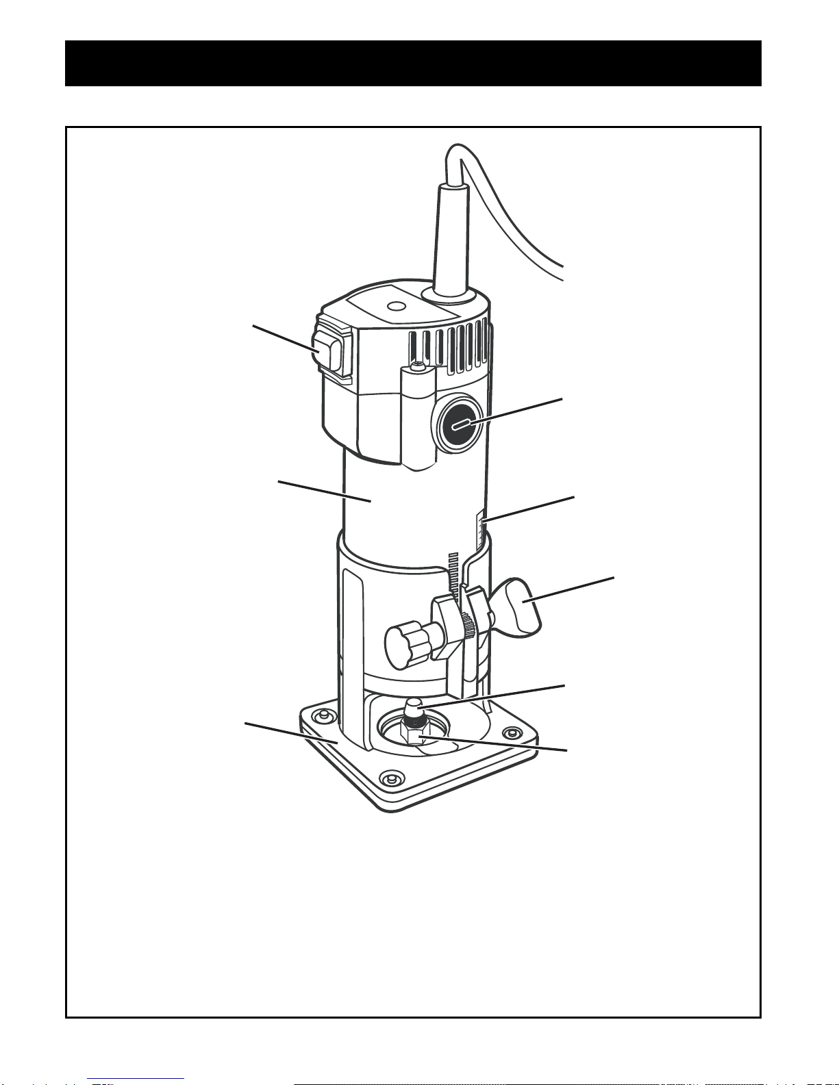
1. KNOW YOUR POWER TOOL. Read owners manual
carefully. Learn its applications and limitations as well as
the specific potential hazards related to this tool.
2. GUARD AGAINST ELECTRICAL SHOCK BY
PREVENTING BODY CONTACT WITH GROUNDED
SURFACES. For example, pipes, radiators, ranges,
refrigerator enclosures.
3. KEEP WORK AREA CLEAN. Cluttered areas and
benches invite accidents.
4. AVOID DANGEROUS ENVIRONMENT. Don't use power
tools in damp or wet locations or expose to rain. Keep
work area well lit.
5. KEEP CHILDREN AND VISITORS AWAY. Visitors should
wear safety glasses and be kept a safe distance from
work area. Do not let visitors contact tool or extension
cord.
6. STORE IDLE TOOLS. When not in use, tools should be
stored in a dry and high or locked-up place, out of reach
of children.
7. DON'T FORCE TOOL. It will do the job better and safer
at the rate at which it was designed.
8. USE RIGHT TOOL. Don't force small tool or attachment
to do the job of a heavy duty tool. Don't use tool for
purpose not intended.
9. DRESS PROPERLY. Do not wear loose clothing or
jewellery. They can be caught in moving parts. Rubber
gloves and non-skid footwear are recommended when
working outdoors. Also wear protective hair covering to
contain long hair.
10.ALWAYS WEAR SAFETY GLASSES. Everyday
eyeglasses have only impact resistant lenses, they are
not safety glasses.
11. PROTECTYOUR LUNGS. Wear a dust mask if operation
is dusty.
12.PROTECT YOUR HEARING. Wear hearing protection
during extended periods of operation.
13.DON'T OVERREACH. Keep proper footing and balance
at all times. Do not use tool on a ladder or unstable
support. Secure tools when working at elevated levels.
14.MAINTAIN TOOLS WITH CARE. Keep tools sharp and
clean for better and safer performance. Follow
instructions for lubricating and changing accessories.
15.REMOVE ADJUSTING KEYS AND WRENCHES. Form
a habit of checking to see that keys and adjusting
wrenches are removed from tool before turning it on.
16.NEVER USE IN AN EXPLOSIVE ATMOSPHERE.
Normal sparking of the motor could ignite fumes.
17.KEEP HANDLES DRY, CLEAN AND FREE FROM OIL
AND GREASE. Always use a clean cloth when cleaning.
Never use brake fluids, gasoline, petroleum based
products, or any strong solvents to clean your tool.
18.STAY ALERT AND EXERCISE CONTROL. Watch what
you are doing and use common sense. Do not operate
tool when you are tired. Do not rush operation of tool.
19.CHECK DAMAGED PARTS. Before further use of the
tool, a guard or any other part that is damaged should
be carefully checked to determine that it will operate
properly and perform its intended function. Check for
alignment of moving parts, binding of moving parts,
breakage of parts, mounting and any other conditions
that may affect its operation. A guard or any other part
that is damaged should be properly repaired or replaced
by an authorised service centre.
20.DO NOT USE TOOL IF SWITCH DOES NOT TURN IT
ON AND OFF. Have defective switches replaced by
authorised service centre.
21.DO NOT OPERATE THIS TOOL WHILE UNDER THE
INFLUENCE OF DRUGS, ALCOHOL OR ANY
MEDICATION.
22.THE APPLIANCE IS NOT INTENDED FOR USE BY
YOUNG OR INFIRM PERSONS WITHOUT
SUPERVISION. YOUNG CHILDREN SHOULD BE
SUPERVISEDTO ENSURETHATTHEY DO NOT PLAY
WITH THE APPLIANCE.
RULES FOR SAFE OPERATION
SAVETHESE INSTRUCTIONS
FOR FUTURE REFERENCE
Due to continued product
refinement policy, product features
and specifications can and will
change without notice. Check
current features and specifications
with your retailer.
SAFETY ALERT SYMBOL. Indicates caution
or warning. May be used in conjunction with
other symbols or pictures.
WARNING: Failure to obey a safety warning can
result in serious injury to yourself or to others.
Always follow the safety precautions to reduce
the risk of fire, electric shock and personal injury.
WARNING: Do not attempt to operate this tool
until you have read thoroughly and understood
completely, safety rules, etc. contained in this
manual. Failure to comply can result in
accidents involving fire, electric shock or serious
personal injury. Save owners manual and
review frequently for continuing safe operation
and instructing others who may use this tool.
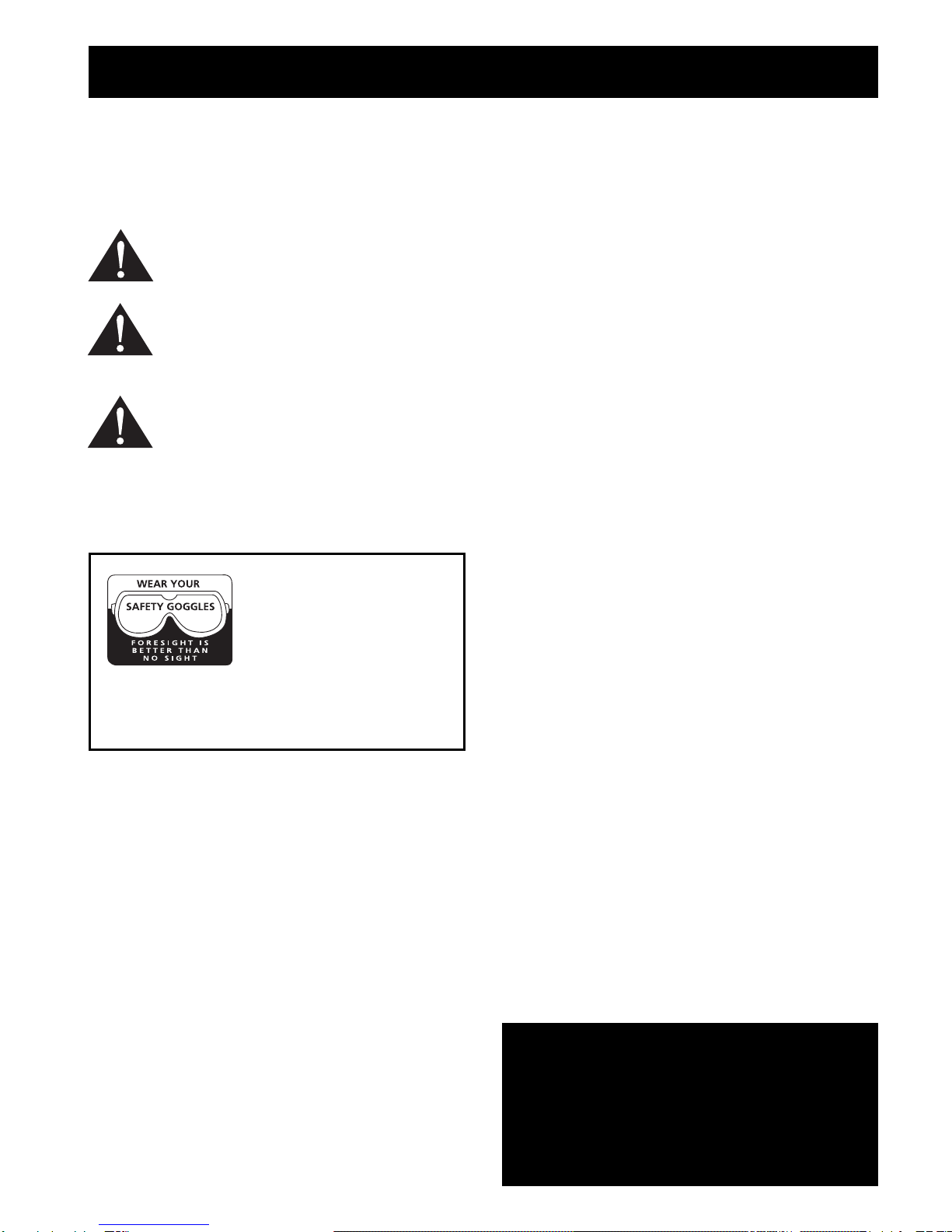
The operation of any tool can
result in foreign objects being
thrown into your eyes, which can
result in severe eye damage.
Before beginning power tool
operation, always wear safety
goggles or safety glasses with side shields and a full
face shield when needed.We recommend Wide Vision
Safety Mask for use over eyeglasses or standard safety
glasses with side shields.
Page 2

FEATURES
1. On/ Off Switch
2. Base
3. External Brush Cap
4. Motor Housing
5. Collet
6. Collet Nut
7. Depth Of Cut Scale
8. Wing Bolt
Page 3
1
1N.
1
/
2
1
2
3
4
7
8
5
6

You may use the trimming and routing kit for the
purposes listed below:
Routing all types of timber.
Cabinet making, trimming counter tops and finishing
work.
Trimming wood and plastics.
INSTALLING/REMOVING CUTTERS (Fig. 1)
UNPLUGYOURTRIMMER.
Place your trimmer upside down on a workbench in
order to gain easy access to the spindle and collet nut.
Place the small end of one of the wrenches provided
on the spindle flats.This will hold the spindle
stationary.
Place the large end of the other wrench provided onto
the collet nut.Rotate wrench counterclockwise to
loosen collet nut.
APPLICATIONS
Page 4
ASSEMBLY
WARNING:
WARNING:
Failure to unplug your trimmer could result in
accidental starting causing serious injury.
WARNING:
If installing a cutter for the first time, it can be installed
once the collet nut is loose. If changing cutters, cutter
will easily slip from collet after loosening collet nut.
The collet is machined to precision tolerances to fit
cutters with 6.35 mm diameter shanks.
With your trimmer still upside down on a workbench,
insert shank of cutter into collet.The shank of your
cutter should be close to but not touching the bottom of
the collet.This allows for expansion when the cutter
gets hot.
Tighten the collet nut securely by turning clockwise
with the wrench provided.
TO SET THE DEPTH OF CUT (Fig. 2)
UNPLUG YOUR TRIMMER
Loosen the wing bolt and move the base until the tip of
cutter touches the work surface.The depth of cut is
zero at this point.
Position your trimmer so that the cutter can extend
below the sub base for desired depth of cut setting.
Move the base to obtain the desired depth of cut.The
distance the cutter moves will be indicated on the
depth of cut scale.Each mark on the scale indicates a
1.6 mm change in depth setting. Indicator points are
located on the base.
Securely tighten the wing bolt.
ASSEMBLY
Wrench On
Collet Nut Cutter
Wrench On
Spindle Flats
Fig. 1
If you are changing a cutter immediately after
use, be careful not to touch the cutter or collet
with your hands or fingers.They may get burnt
due to the heat buildup from cutting.
Always use the wrench provide.
Your trimming and routing kit should never be
connected to a power supply when you are
assembling parts, making adjustments,
installing or removing cutters, or when not in
use. Disconnecting your trimmer will prevent
accidental starting that could cause serious
injury.
WARNING:
If collet nut is not tightened securely, cutter
may come out during use, causing serious
personal injury.
WARNING:
Avoid open area of trimmer base. Serious
personal injury will result from contact with a
rotating cutter.
WARNING:
Failure to unplug your trimmer could result in
accidental starting causing serious injury.
WARNING:
Do not use cutters that are larger in diameter
than the opening in trimmer base. Use of
such cutters will come in contact with the
trimmer base and damage both the cutter
and trimmer base. Possible loss of control or
create other hazardous conditions that could
cause possible serious personal injury.
WARNING:
Do not use cutters with undersized shanks.
Undersized shanks will not tighten properly
and could be thrown from tool causing injury.

CHANGINGTHE ROTATION SPEED (FIG. 7)
Page 5
STRAIGHT FENCE (Fig. 3)
It is helpful to use the straight fence when trimming the
straight edge or engraving a groove.
Tighten the screw to install straight fence.Loosen the
wing bolt to adjust the required distance between bit and
fence.Then tighten the bolt. Keep the fence evenwith the
workpiece edge when cutting and moving the tool.
OPERATION
CIRCUMFERENCE CUTTING (Fig. 4 - 6)
By installing the straight fence and connector you can
make a circumference cut. Available radius cuts, shown
from bit to central hole.
Minimum radius: 70mm
Maximum radius: 220mm
Attention: The straight fence is unable to cut a radius
between 172mm and 186mm.
Correctly aline the fence central hole to the required
circle’s center. Pushing a nail, with a diameter no more
than 6mm into the hole, to firmly fix the fence.Move the
tool around the nail in a clockwise direction.
ADJUSTINGTHE GUIDE (Fig. 7 & 8)
It is much easier to use the adjusting guide for curve
cutting and trimming. Move the guide along the curved
edge.
Tighten the screw to install the adjusting guide on the tool
base plate.Loosen the wing bolt to adjust the guide.
Then tighten the screw firmly to fix the adjusting guide at
a required distance.
Install the guide into the base by bolt A. Adjust the
distance between the bit and base by bolt B, then fasten
by bolt C.
OPERATION
Fence
Connector
Wing Bolt
Washer
Center Hole
Bolt
Fig. 4 Fig. 5
1
1N.
1
/
2
1
CM
1
2
3
1N.
12
/
Fig. 6
Fig. 3
WARNING:
Always wear safety goggles or safety glasses
with side shields when using your trimmer.
Failure to do so could result in dust,
shavings, chips, loose particlesor foreign
objects being thrown into your eyes resulting
in possible serious injury. If the operation is
dusty, also wear a face or dust mask.
WARNING:
When turning your trimmer ON, be prepared
for start-up torque.Always have a firm grasp
of your trimmer before starting. Because of
the high cutter speed rotation your trimmer
has a tendency to twist, jerk or grab in your
hands during start-up. If not prepared, this
can cause a loss of control resulting in
possible serious injury.
Wing Bolts
Fence
Center Hole
Nail
Fence
Screw
Fig. 2
Depth of
Cut Scale
Wing Bolt
Table of contents
Other Ryobi Power Tools manuals

Ryobi
Ryobi BD513 Operation manual

Ryobi
Ryobi EOJ550K Operation manual

Ryobi
Ryobi JS451L User manual

Ryobi
Ryobi RA-NC1565-K User manual

Ryobi
Ryobi P2907 User manual

Ryobi
Ryobi RPC4 User manual

Ryobi
Ryobi RRS1801M User manual

Ryobi
Ryobi HG600 User manual

Ryobi
Ryobi HG500 User manual

Ryobi
Ryobi R18HG-0 User manual

Ryobi
Ryobi R18CG User manual

Ryobi
Ryobi MC100L User manual

Ryobi
Ryobi RHT5555R User manual

Ryobi
Ryobi PSBRC26 User manual

Ryobi
Ryobi AIRGRIP EZ REACH ELB001 User manual

Ryobi
Ryobi RCG18 User manual

Ryobi
Ryobi RMT2004 User manual

Ryobi
Ryobi P730 Quick setup guide

Ryobi
Ryobi YG100P User manual

Ryobi
Ryobi R18MI User manual