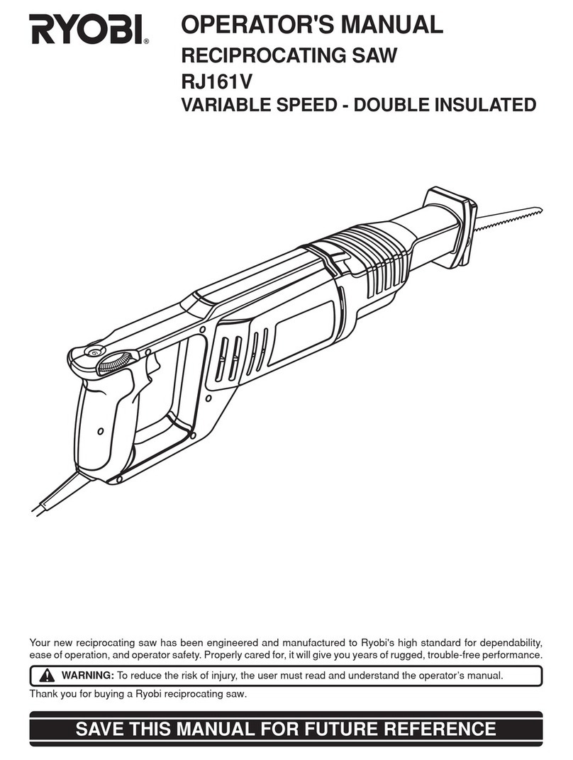
Ryobi RJ150V Operation manual

OWNER'S OPERATING MANUAL
RECIPROCATING SAW
RJ150V
DOUBLE INSULATED
SPECIFICATIONS:
Length of stroke 1 in. (25.4mm)
Strokes per minute 0-2300 spm
Switch Adjustable variable speed
Rating 120 volts, 60 Hz, AC
Input 6.0 amps
Net weight 6.5 lbs.
THANK YOU FOR BUYING A RYOBI RECIPROCATING SAW.
Your new saw has been engineered and manufactured to Ryobi's high standard for dependability, ease of operation, and
operator safety. Properly cared for, it will give you years of rugged, trouble-free performance.
CAUTION: Carefully read through this entire owner's manual before using your new saw. Pay close attention to
the Rules for Safe Operation, Warnings, and Cautions. If you use your saw properly and only for what it is intended, you will
enjoy years of safe, reliable service.
Thank you again for buying Ryobi tools.
SAVE THIS MANUAL FOR FUTURE REFERENCE

Page 2
RULES FOR SAFE OPERATION
DOUBLE INSULATION
Your Ryobi power tool is double insulated. This means you
areseparatedfromthetool'selectricalsystembytwocomplete
sets of electrical insulation. This extra layer of insulation is
intended to protect the user from electrical shock due to a
break in the wiring insulation. All exposed metal parts are
isolated from the internal metal motor components with
protecting insulation. Double insulated tools do not need to
be grounded.
IMPORTANT
Servicingofatoolwithdoubleinsulationrequiresextreme
careandknowledgeofthesystemandshouldbeperformed
only by a qualified service technician. For service we
suggest you return the tool to your nearest Ryobi
FACTORY SERVICE CENTER or other AUTHORIZED
SERVICE ORGANIZATION for repair. When servicing
use only identical Ryobi replacement parts.
Lookforthissymboltopointoutimportantsafetyprecautions.
It means attention!!! Your safety is involved.
The operation of any reciprocating saw can result in foreign objects being thrown into
your eyes, which can result in severe eye damage. Before beginning power tool
operation, always wear safety goggles or safety glasses with side shields and a full face
shield when needed. We recommend Wide Vision Safety Mask for use over eyeglasses
or standard safety glasses with side shields.
SAFETY GLASSES
SAFETY GLASSES
FORESIGHTIS BETTER
THAN NO SIGHT
FORESIGHTIS BETTE
R
THAN NO SIGHT
WEAR YOUR
WARNING:
WARNING:
The double insulated system is intended to protect the
user from shock resulting from a break in the tool's
internal wiring. Observe all normal safety precautions
related to avoiding electrical shock.
WARNING:
Do not attempt to operate this tool until you have read
thoroughly and understand completely all instructions,
safety rules, etc. contained in this manual. Failure to
comply can result in accidents involving fire, electric
shock, or serious personal injury. Save owner's manual
and review frequently for continuing safe operation, and
instructing others who may use this tool.
THE PURPOSE OF SAFETY SYMBOLS IS TO ATTRACT YOUR ATTENTION TO POSSIBLE DANGERS. THE
SAFETY SYMBOLS, AND THE EXPLANATIONS WITH THEM, DESERVE YOUR CAREFUL ATTENTION AND
UNDERSTANDING. THE SAFETY WARNINGS DO NOT BY THEMSELVES ELIMINATE ANY DANGER. THE
INSTRUCTIONS OR WARNINGS THEY GIVE ARE NOT SUBSTITUTES FOR PROPER ACCIDENT PREVENTION
MEASURES.
SYMBOL MEANING
SAFETY ALERT SYMBOL:
Indicatescautionorwarning.Maybe used in conjunction with other symbols orpictographs.
WARNING: Failure to obey a safety warning can result in serious injury to yourself or to
others. Always follow the safety precautions to reduce the risk of fire, electric shock and
personal injury.
CAUTION: Failuretoobeyasafetywarningmayresultinpropertydamageorpersonalinjury
toyourselfortoothers.Alwaysfollowthesafetyprecautionsto reducetheriskoffire,electric
shock and personal injury.

Page 3
READ ALL INSTRUCTIONS
1. KNOW YOUR POWER TOOL - Read owner's
manualcarefully.Learnitsapplicationsandlimita-
tions as well as the specific potential hazards
related to this tool.
2. GUARD AGAINST ELECTRICAL SHOCK BY
PREVENTING BODY CONTACT WITH
GROUNDED SURFACES. For example: Pipes,
radiators, ranges, refrigerator enclosures.
3. KEEP GUARDS IN PLACE and in working order.
4. KEEPWORKAREACLEAN.Clutteredareasand
benches invite accidents.
5. AVOIDDANGEROUSENVIRONMENT.Don'tuse
power tool in damp or wet locations or expose to
rain. Keep work area well lit.
6. KEEP CHILDREN AND VISITORS AWAY. All
visitors should wear safety glasses and be kept a
safe distance from work area. Do not let visitors
contact tool or extension cord.
7. STORE IDLE TOOLS. When not in use, tools
should be stored in a dry, high or locked-up place
- out of the reach of children.
8. DON'T FORCE TOOL. It will do the job better and
safer at the rate for which it was designed.
9. USE RIGHT TOOL. Don't force small tool or at-
tachment to do the job of a heavy duty tool. Don't
use tool for purpose not intended - for example -
Don't use a circular saw for cutting tree limbs or
logs.
10. WEAR PROPER APPAREL. Nolooseclothing or
jewelry to get caught in moving parts. Rubber
gloves and non-skid footwear are recommended
whenworkingoutdoors. Also,wearprotectivehair
coveringtocontainlonghairandkeepitfrombeing
drawn into air vents.
11. ALWAYS WEAR SAFETY GLASSES. Everyday
eyeglasseshaveonlyimpact-resistantlenses;they
are NOT safety glasses.
12. PROTECT YOUR LUNGS. Wear a face or dust
mask if operation is dusty.
13. PROTECT YOUR HEARING. Wear hearing pro-
tection during extended periods of operation.
14. DON'TABUSECORD.Nevercarrytoolbycordor
yank it to disconnect from receptacle. Keep cord
away from heat, oil and sharp edges.
15. SECURE WORK. Use clamps or a vise to hold
work. Both hands are needed to operate the tool.
16. DON'T OVERREACH. Keep proper footing and
balance at all times. Do not use on a ladder or
unstable support.
17. MAINTAINTOOLSWITHCARE.Keeptoolssharp
at all times, and clean for best and safest perfor-
mance. Follow instructions for lubricating and
changing accessories.
18. DISCONNECT TOOLS. When not in use, before
servicing,orwhen changingattachments,blades,
bits,cutters,etc., all tools shouldbe disconnected
from power supply.
19. REMOVEADJUSTINGKEYSANDWRENCHES.
Form habit of checking to see that keys and
adjusting wrenches are removed from tool before
turning it on.
20. AVOID ACCIDENTAL STARTING. Don't carry
plugged-in tools with finger on switch. Be sure
switch is off when plugging in.
21. MAKE SURE YOUR EXTENSION CORD IS IN
GOOD CONDITION. When using an extension
cord,besuretouseoneheavyenoughtocarrythe
currentyourproductwilldraw.Anundersizedcord
will cause a drop in line voltage resulting in loss of
powerandoverheating.Awiregagesize(A.W.G.)
of at least 12 is recommended for an extension
cord 100 feet or less in length. A cord exceeding
100 feet is not recommended. If in doubt, use the
next heavier gage. The smaller the gage number,
the heavier the cord.
22. OUTDOOR USE EXTENSION CORDS. When
tool is used outdoors, use only extension cords
intended for use outdoors and so marked.
23. KEEP BLADES CLEAN AND SHARP. Sharp
blades minimize stalling and kickback. Also, keep
blades properly tightened at all times.
24. KEEP HANDS AWAY FROM CUTTING AREA.
Keep hands away from blades. Do not reach
underneath work while blade is cutting. Do not
attempt to remove material while blade is cutting.
25. NEVERUSEINANEXPLOSIVEATMOSPHERE.
Normal sparking of the motor could ignite fumes.
26. INSPECT TOOL CORDS PERIODICALLY and if
damaged,haverepaired by an authorizedservice
center. Stay constantly aware of cord location.
27. INSPECTEXTENSIONCORDSPERIODICALLY
and replace if damaged.
28. KEEP HANDLES DRY, CLEAN, AND FREE
FROM OIL AND GREASE. Always use a clean
clothwhencleaning.Neverusebrakefluids,gaso-
line, petroleum-based products or any strong sol-
vents to clean your tool.
Page 4
RULES FOR SAFE OPERATION (Continued)
29. STAYALERT. Watchwhatyouaredoingand use
commonsense.Do notoperatetool when youare
tired. Do not rush.
30. CHECKDAMAGEDPARTS.Beforefurtheruseof
the tool, a guard or other part that is damaged
shouldbecarefullycheckedtodeterminethatitwill
operate properly and perform its intended func-
tion. Check for alignment of moving parts, binding
ofmovingparts, breakageof parts,mounting, and
any other conditions that may affect its operation.
A guard or other part that is damaged should be
properly repaired or replaced by an authorized
service center unless indicated elsewhere in this
instruction manual.
31. DO NOT USE TOOL IF SWITCH DOES NOT
TURN IT ON AND OFF. Have switches replaced
by an authorized service center.
32. CUTTING INTO ELECTRICAL WIRING IN
WALLS CAN CAUSE BLADE AND METAL
PARTS TO BECOME ELECTRICALLY LIVE.
Grasp only the handle(s) provided on the tool and
be sure that hidden electrical wiring, water pipes,
or any mechanical hazards are not in blade path.
33. Inspect for and remove all nails from timber
before cutting.
34. DRUGS,ALCOHOL,MEDICATION.Donotoper-
atetoolwhileundertheinfluenceofdrugs,alcohol,
or any medication.
35. WHEN SERVICING USE ONLY IDENTICAL
RYOBI REPLACEMENT PARTS.
36. POLARIZEDPLUGS. Toreducetheriskofelectric
shock, this tool has a polarized plug (one blade is
widerthantheother).Thisplugwillfitinapolarized
outlet only one way. If the plug does not fit fully in
the outlet, reverse the plug. If it still does not fit,
contact a qualified electrician to install the proper
outlet. Do not change the plug in any way.
37. WARNING:TOAVOIDPOSSIBLESERIOUSIN-
JURY, KEEP HANDS AND FINGERS FROM
BETWEEN THE MOTOR HOUSING AND SAW
BLADE CLAMP.
38. SAVE THESE INSTRUCTIONS. Refer to them
frequently and use them to instruct others who
may use this tool. If you loan someone this tool,
loan them these instructions also.
EXTENSION CORDS
Theuseofanyextensioncordwillcausesomelossofpower.
Tokeepthelosstoaminimumandtopreventtooloverheating,
use an extension cord that is heavy enough to carry the
current the tool will draw.
A wire gage size (A.W.G.) of at least 14 is recommended for
an extension cord 50 feet or less in length. A wire gage size
(A.W.G.)ofatleast12isrecommendedforanextensioncord
50 - 100 feet in length. When working outdoors, use an
extension cord that is suitable for outdoor use. The cord's
jacket will be marked WA.
CAUTION:
Keep extension cords away from the cutting area and
position the cord so that it will not get caught on lumber,
tools, etc. during cutting operation.
WARNING:
Check extension cords before each use. If damaged
replaceimmediately.Neverusetoolwithadamagedcord
since touching the damaged area could cause electrical
shock resulting in serious injury.
SAVE THESE INSTRUCTIONS
WARNING:
Ifany parts aremissing,donotoperateyour saw untilthe
missing parts are replaced. Failure to do so could result
in possible serious personal injury.
WARNING:
Do not allow familiarity with your saw to make you
careless. Remember that a careless fraction of a second
is sufficient to inflict severe injury.

Page 5
UNPACKING
Your saw has been shipped completely assembled and
ready for use. Inspect it carefully to make sure no breakage
or damage has occurred during shipping. If any parts are
damaged or missing, contact your nearest Ryobi dealer to
obtain replacement parts before attempting to operate saw.
An owner's operating manual and warranty registration are
also included.
KNOW YOUR RECIPROCATING SAW
Beforeattemptingtouseyoursaw,familiarizeyourselfwithall
operating features and safety requirements.
See Figure 1.
OPERATION
ALLEN WRENCH HOLDER
A convenient feature on your saw is an allen wrench holder.
It is located on the bottom portion of your saw's handle. It is
ELECTRICAL CONNECTION
Your saw has a precision built Ryobi electric motor. It should
beconnectedtoapowersupplythatis120volts,60Hz,AC
only (normal household current). Do not operate this tool
ondirectcurrent(DC).Avoltagedropofmorethan10percent
willcause a loss of powerand themotor will overheat.If your
tool does not operate when plugged into an outlet, double-
check the power supply.
Fig. 1
TRIGGER
BLADE
CLAMP
SCREW
FLAT HEAD SCREW
(FOR FLUSH CUTTING)
BASE
ASSEMBLY
VARIABLE SPEED
CONTROL SELECTOR
LOCK-ON
BUTTON
ALLEN WRENCH
ALLEN
WRENCH HOLDER
SET SCREW
(SECURES BASE ASSEMBLY)
BLADE
CLAMP
BLADE
TO ROTATE BASE
ASSEMBLY DOWN
TO ROTATE BASE
ASSEMBLY UP
convenient for storing allen wrench when not in use.
See
Figure 1.
PIN

Page 6
VARIABLE SPEED
CONTROL SELECTOR
OPERATION
WARNING:
Always wear safety goggles or safety glasses with side
shieldswhenoperatingyourreciprocatingsaw.Failureto
dosocouldresultinforeignobjectsbeingthrownintoyour
eyes resulting in possible serious injury.
If you desire to lock the switch on at a given speed, depress
theswitchtrigger, push in and hold the "lock-on"button,then
while holding the "lock-on" button pushed in release the
switch trigger. Next, adjust the variable speed control selec-
tor until the desired speed is reached.
NOTE:IFTHEVARIABLESPEEDCONTROLSELECTOR
IS FULLY TURNED IN THE COUNTERCLOCKWISE
DIRECTION (ZERO SETTING) YOUR SAW MAY NOT
RUN. ADJUST THE VARIABLE SPEED CONTROL
SELECTOR TO MAKE SAW OPERATE.
IFYOU DESIRE NOT TO USETHE VARIABLE SPEED
CONTROL SELECTOR, TURN IT IN THE FULL
CLOCKWISE DIRECTION. THIS WILL ALLOW THE
SPEED OF YOUR SAW TO BE FULLY CONTROLLED
BY THE AMOUNT OF SWITCH TRIGGER
DEPRESSION.
Avoid running your saw at low speeds for extended periods
of time. Running at low speeds under constant usage may
cause the motor of your saw to become overheated. If this
occurs, cool your saw by running it without a load and at full
speed. WARNING:
Your saw should never be connected to power supply
when you are assembling parts, making adjustments,
installingorremovingblades,whencleaning,orwhennot
in use. Disconnecting your saw will prevent accidental
starting that could cause serious injury.
BLADE SELECTION
To obtain the best performance from your saw it is important
to select a specific blade for the particular application and
type of material you wish to cut. By doing this you will get a
smoother faster cut and prolong blade life. Replacement
blades for this saw are available from your nearest Ryobi
dealer.
Fig. 2
SWITCH
See Figure 2.
To turn your reciprocating saw ON, depress switch trigger.
Release switch trigger to turn your saw OFF.
LOCK-ON BUTTON
See Figure 2.
Your saw is equipped with a "lock-on" feature, which is
convenient when continuous cutting for extended periods of
timeis required. To lock-on,depress theswitch trigger,push
in and hold the "lock-on" button located on the side of the
handle,thenreleaseswitchtrigger.Release"lock-on"button
and your saw will continue running.
Toreleasethelock,depress theswitchtrigger andreleaseit.
DO NOT lock the trigger on heavy jobs where your saw may
have to be stopped quickly.
WARNING:
When using your saw with the switch lock-on, keep your
finger near the trigger and be prepared to disengage the
"lock-on"featureat all times. Failure todo so could result
in loss of control leading to possible serious injury.
Ifyouhavethe"lock-on"featureengagedduringuseandyour
saw becomes disconnected from power supply, disengage
the "lock-on" feature immediately.
WARNING:
Before connecting your saw to power supply source,
always check to be sure it is not in "Lock-on" position
(depress and release switch trigger). Failure to do so
could result in accidental starting of saw resulting in
possible serious injury. Also, do not lock the trigger on
jobs where your saw may need to be stopped suddenly.
VARIABLE SPEED
See Figure 2.
Yourreciprocatingsaw has a variable speed controlselector
designed to allow operator control and adjustment of speed
and power limits. The speed and power of your saw can be
increasedordecreasedbyrotatingthevariablespeedcontrol
selector in the direction of the arrows shown in figure 2.
NOTE: Hold your saw in normal operating position and turn
the variablespeedcontrolselectorclockwisetoincreasethe
speed and power of your saw. Turn counterclockwise to
decrease the speed and power of your saw.
LOCK-ON
BUTTON
TO
INCREASE
SPEED
TO
DECREASE
SPEED

Page 7
ALLEN
WRENCH
Fig. 4
Fig. 3
TO INSTALL BLADES
See Figure 3.
1. UNPLUG YOUR SAW.
WARNING:
Failure to unplug your saw could result in accidental
starting causing serious injury.
2. Removethe5/32in.allenwrenchprovidedwiththissaw
fromallenwrenchholder.NOTE:Allenwrenchholderis
located in bottom portion of saw handle.
See Figure 1.
3. Loosenthebladeclampscrewenoughtopermitthesaw
bladetobeinsertedbetween blade clamp and saw bar.
4. Aligntheholeintheshankofthebladewiththepininthe
bladeclamp,thenseatbothintotheholeinthesawbar.
5. Tightenbladeclampscrewsecurely.Donotovertighten
screw or use an aid with allen wrench.
6. Remove allen wrench and store it in allen wrench
holder.
NOTE: There may be times when the blade clamp sticks to
the saw bar and will not loosen enough to allow blades to be
installedorremoved.Ifthishappens,loosenthebladeclamp
screwwiththeallenwrench,thentaplightlyontheendof the
allen wrench with a mallet.
See Figure 4.
BASE ASSEMBLY
See Figure 5.
The base assembly of your reciprocating saw pivots up and
downapproximately15°inbothdirections.Italsoisadjustable,
allowingtheuseofthebladeteethatdifferentpositionsonthe
blade.
Threecuttingpositionsareavailablewhenmakingcutsusing
regular blades. Three cutting positions are available when
making cuts using flush cutting blades.
TO CHANGE POSITIONS OF THE BASE ASSEMBLY:
1. UNPLUG YOUR SAW.
WARNING:
Failure to unplug your saw could result in accidental
starting causing serious injury.
2. Loosen the set screw in the gear frame with the 5/32 in.
allen wrench mentioned above.
3. Reposition base assembly and align in the desired
notch. NOTE: When changing from cutting with regular
bladestocuttingwithflushcuttingblades,baseassembly
must be turned clockwise 90°. Turn counterclockwise
90°whenchangingfromcuttingwithflushcuttingblades
to cutting with regular blades.
4. Retightensetscrewsecurely.Donotovertightenscrew
or use an aid with allen wrench.
5. Remove allen wrench and store it in allen wrench holder.
OPERATION
Fig. 5
NOTCH
ALLEN
WRENCH
PIN
BLADE
CLAMP
SAW BAR
BLADE
CLAMP SCREW
BLADE
MALLET
BLADE CLAMP
BLADE
CLAMP SCREW
BASE ASSEMBLY
GEAR FRAME
SET SCREW
NOTCHES FOR
REGULAR CUTS
ALLEN
WRENCH
SAW BAR

Page 8
BASE ASSEMBLY IN
REGULAR CUTTING POSITION
OPERATION
Fig. 6
TO INSTALL FLUSH CUTTING BLADES
See Figures 6 and 7.
Flush cutting blades should be used when making close or
flush cuts to walls.
1. Plug your reciprocating saw into power supply source.
2. Depress and release the switch trigger of your saw in
quick,shortstartsandstopsuntilbladeclampisinitsfull
rear position.
See Figure 6.
3. UNPLUG YOUR SAW.
WARNING:
Failure to unplug your saw could result in accidental
starting causing serious injury.
4. Using the 5/32 in. allen wrench provided with your saw,
loosen the blade clamp screw and remove regular saw
blade.
5. Tightenbladeclampscrewsecurely.Donotovertighten
screw or use an aid with allen wrench.
6. Loosen set screw and turn base assembly clockwise
90°.
See Figure 7.
7. Align in desired notch, then tighten set screw securely.
8. Remove allen wrench and store it in allen wrench
holder.
9. Insertflushcuttingbladeontopofbladeclampasshown
in figure 6.
10. Align hole in blade shank with pin on blade clamp.
11. Using the flat head screw provided, secure blade to
blade clamp.
See Figure 6.
12. Tighten flat head screw securely.
GENERAL CUTTING
See Figure 8.
Hold your saw firmly in front of and clearly away from you.
Makesuresawbladeis clear of any foreign material and that
power cord and extension cord are out of the blade path. Be
surematerialtobecutisheldfirmly.Smallworkpiecesshould
be securely clamped in a vise or with clamps to the work
benchortable.Markthelineofcutclearly.Depressthetrigger
switch starting the cutting action, set the base assembly
againstthework,thenmovethebladeintothework.DONOT
FORCE. Use only enough pressure to keep the saw cutting.
Let the blade and saw do the work.
PLUNGE CUTTING
See Figure 9.
Mark the line of cut clearly. Choose a convenient starting
pointinsidetheareatobecutoutandplacethetipoftheblade
overthatpoint.Restfrontedgeofbaseassemblyonworkand
hold firmly in position. NOTE: Make sure blade does not
touch work until motor reaches full speed, since this could
cause loss of control resulting in serious injury. With saw
blade at full cutting speed, slowly tilt saw downward until tip
of blade starts cutting work. After blade penetrates work, tilt
saw until blade is perpendicular to the work. Fig. 8
Fig. 7
PIN
BLADE
CLAMP
FLAT
HEAD SCREW
FLUSH
CUTTING BLADE
BASE ASSEMBLY IN FLUSH
CUTTING POSITION
SET
SCREW
FLUSH
CUTTING NOTCHES
BLADE CLAMP IN
FULL REAR POSITION

Page 9
FLUSH CUTTING
See Figure 10.
Your saw has been designed with a flush cutting feature
which permits cutting close to floors or walls. To fit your
cuttingrequirements,cutsmaybemadeineitherdirectionby
reversing the position of the blade in the blade clamp. See
page 8 for instructions on installing Flush Cutting Blade.
METAL CUTTING
See Figure 11.
Metalssuchassheetsteel,pipe,steelrods,aluminum,brass,
and copper may be cut with your saw. Be careful not to twist
or bend the saw blade. DO NOT FORCE. We recommend
cuttingoilwhencuttingmostsoftmetalsandsteel.Cuttingoil
will also keep blades cool, increase cutting action, and
prolong blade life.
Never use gasoline since normal sparking of motor could
ignite fumes. Clamp the work firmly and cut close to the
clamping point to eliminate any vibration of the work being
cut. When cutting conduit pipe or angle iron, clamp work in a
vise if possible and cut close to the vise. To cut thin sheet
material, "sandwich" the material between hardboard or
plywood and clamp the layers to eliminate vibration and
material tearing.
LUBRICATION
All of the bearings in this tool are lubricated with a sufficient
amount of high grade lubricant for the life of the unit under
normaloperatingconditions.Therefore,nofurtherlubrication
is required.
OPERATION
Fig. 11
Fig. 9
Fig. 10

Page 10
MAINTENANCE
GENERAL
Avoidusingsolventswhencleaningplasticparts.Mostplastics
are susceptible to various types of commercial solvents and
may be damaged by their use. Use clean cloths to remove
dirt, carbon dust, etc.
WARNING:
Do not at any time let brake fluids, gasoline, petroleum-
based products, penetrating oils, etc. come in contact
with plastic parts. They contain chemicals that can
damage, weaken, or destroy plastic.
Ithasbeenfoundthatelectrictoolsaresubjecttoaccelerated
wear and possible premature failure when they are used on
fiberglassboats,sportscars,wallboard,spacklingcompounds,
or plaster. The chips and grindings from these materials are
highlyabrasivetoelectrictoolpartssuchasbearings,brushes,
commutators,etc.Consequently,itisnotrecommendedthat
thistoolbeusedforextendedworkonanyfiberglassmaterial,
wallboard, spackling compounds, or plaster. During any use
on these materials, it is extremely important that the tool is
cleaned frequently by blowing with an air jet.
WARNING:
Always wear safety goggles or safety glasses with side
shieldsduringpowertooloperationorwhenblowingdust.
If operation is dusty, also wear a dust mask.
WARNING: When servicing use only identical Ryobi replacement parts. Use of any other parts may create a
hazard or cause product damage.
ACCESSORIES
Standarduniversal 1/2 inch shank reciprocatingsaw blades
available at your local supplier may be used with your Ryobi
reciprocating saw.

Page 11
NOTES

OWNER'S OPERATING MANUAL
RECIPROCATING SAW
RJ150V
DOUBLE INSULATED
RYOBI AMERICA CORP.
5201 Pearman Dairy Road Anderson, SC 29625-8950
Post Office Box 1207 Anderson, SC 29622-1207
Phone 1-800-525-2579
RYOBI CANADA INC.
Post Office Box 910
Cambridge, Ontario N1R 6K2
Phone 1-800-265-6778
972000-245
10-95 PrintedInU.S.A.
• SERVICE
Now that you have purchased your tool, should a need ever exist for repair parts or
service, simply contact your nearest Ryobi Authorized Service Center. Be sure to
provideallpertinentfactswhenyoucallor visit. Please refer to theinsertorcall1-800-
525-2579 in the United States or 1-800-265-6778 in Canada for your nearest Factory
or Authorized Service Center.
•MODEL NO. AND SERIAL NO.
The model number of this tool will be found on a plate attached to the motor housing.
Please record the model number and serial number in the space provided below.
• HOW TO ORDER REPAIR PARTS
WHEN ORDERING REPAIR PARTS,
ALWAYS GIVE THE FOLLOWING INFORMATION:
•MODEL NUMBER
•SERIAL NUMBER
RJ150V
EXTENSION CORD CAUTION
When using a power tool at a considerable distance from a power
source, be sure to use an extension cord that has the capacity to
handlethecurrentthetoolwilldraw.Anundersizedcordwillcause
a drop in line voltage, resulting in overheating and loss of power.
Use the chart to determine the minimum wire size required in an
extension cord. Only round jacketed cords should be used.
When working with a tool outdoors, use an extension cord that is
designed for outside use. This is indicated by the letters "WA" on
the cord's jacket.
Before using any extension cord, inspect it for loose or exposed
wires and cut or worn insulation.
**Ampere rating
(on tool faceplate) 0-2.0 2.1-3.4 3.5-5.0 5.1-7.0 7.1-12.0 12.1-16.0
Cord Length Wire Size (A.W.G.)
25' 16 16 16 16 14 14
50' 16 16 16 14 14 12
100' 16 16 14 12 10 —
CAUTION: Keep the extension cord clear of the working
area. Position the cord so that it will not get caught on lumber,
tools or other obstructions while you are working with a power
tool.
**Used on 12 gauge - 20 amp circuit.
Table of contents
Other Ryobi Saw manuals

Ryobi
Ryobi R18MS184 User manual

Ryobi
Ryobi EMS305RG User manual

Ryobi
Ryobi TS-260 II Operation manual

Ryobi
Ryobi SC-160 Operation manual

Ryobi
Ryobi P25013 User manual

Ryobi
Ryobi EMS1422LRG User manual

Ryobi
Ryobi AR46000 User manual

Ryobi
Ryobi RTS10 Configuration guide

Ryobi
Ryobi RTBS18X User manual

Ryobi
Ryobi RCS5133CB User manual
Popular Saw manuals by other brands

Scheppach
Scheppach HS81S Translation of original operating manual

Ribimex
Ribimex RIBITECH PRBAT20/SC165SB User and maintenance manual

Hilti
Hilti DSH 700-X Original operating instructions

Wadkin Bursgreen
Wadkin Bursgreen WB800H manual

Jet
Jet HVBS-7MW Operator's manual

Dimas
Dimas TS 350 F - 02 operating instructions