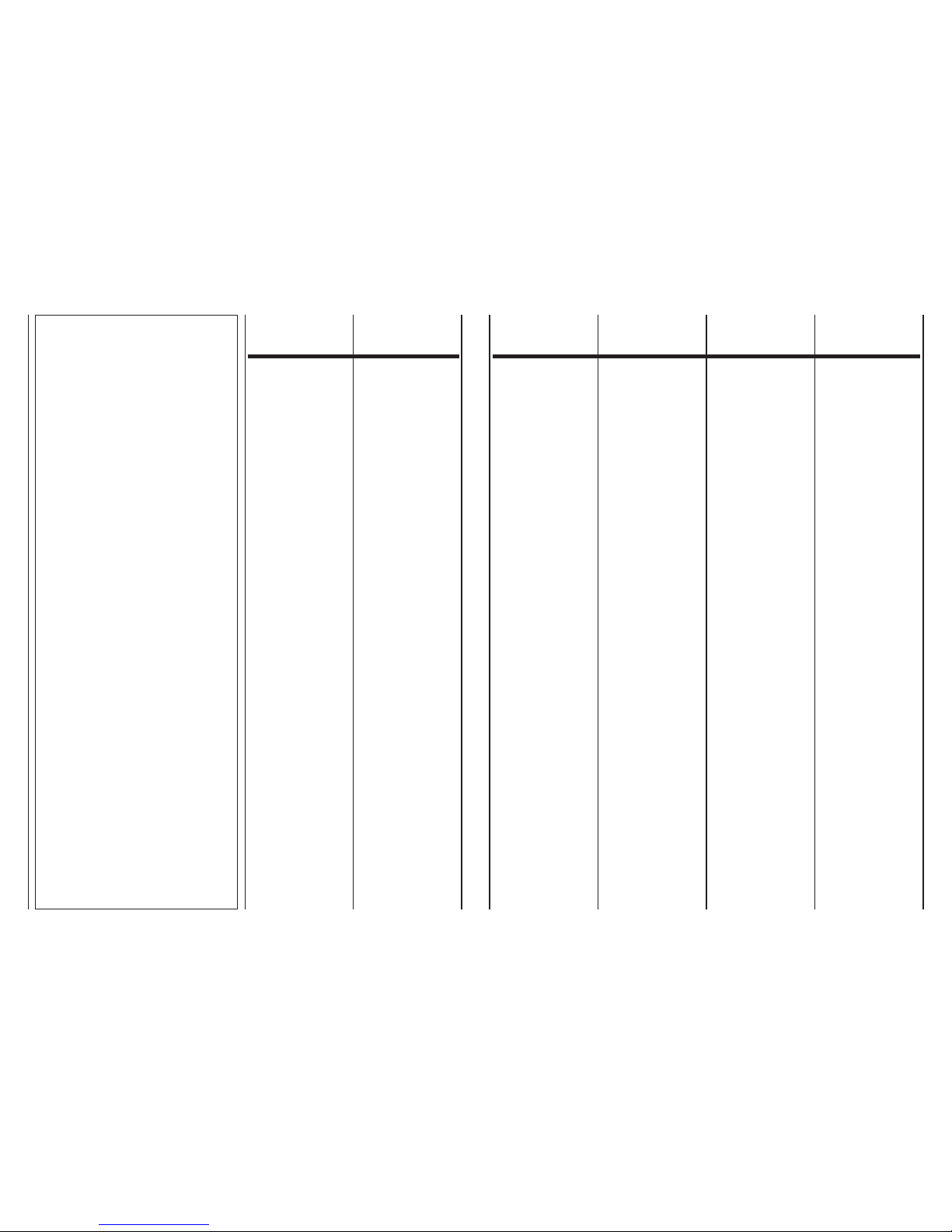
Sabiana CRT MV-MVB Quick start guide

MANUALE DI INSTALLAZIONE,
USO E MANUTENZIONE DEI VENTILCONVETTORI
CARISMA
FAN COIL CARISMA INSTALLATION,
USE AND MAINTENANCE MANUAL
MANUEL D’INSTALLATION, D’UTILISATION
ET D’ENTRETIEN DES VENTILO-CONVECTEURS
CARISMA
HANDBUCH FÜR INSTALLATION,
GEBRAUCH UND WARTUNG
DER GEBLÄSE-KONVEKTOREN CARISMA
MANUAL DE INSTALACIÓN, USO Y MANTENIMIENTO
DE LOS VENTILADORES CONVECTORES
CARISMA
HANDLEITUNG VOOR DE INSTALLATIE, HET GEBRUIK
EN HET ONDERHOUD VAN DE VENTILATORS-CONVECTORS
CARISMA
Via Piave, 53 •20011 Corbetta (MI) •ITALY
Tel. +39.02.97203.1 ric. autom. •Fax +39.02.9777282 - +39.02.9772820
E-mail: info@sabiana.it •Internet: www.sabiana.it
D 04/13
E 04/13
Cod. 4050851
Ventil Carisma
CRT
MV
–
MVB
MO
–
IV
–
IO
Ventil Carisma
CRR
MV

Scopo
Identificazione macchina
Trasporto
Pesi
e dimensioni unità imballata
Note generali alla consegna
Avvertenze generali
Regole fondamentali di sicurezza
Prescrizioni di sicurezza
Limiti di impiego
Smaltimento
Caratteristiche tecniche
Installazione meccanica
Collegamento idraulico
Collegamenti elettrici
Comandi e schemi elettrici
Legenda
Pulizia, manutenzione, ricambi
Ricerca guasti
Perdite di carico lato acqua
Dichiarazione di conformità
Application
Identifying the appliance
Transport
Weights
and dimension packed unit
General notes on delivery
General warnings
Fundamental safety rules
Safety rules
Operating limits
Waste disposal
Technical characteristics
Mechanical installation
Hydraulic connections
Electrical connections
Electrical
controls and wiring diagrams
Legend
Cleaning,
maintenance and spare parts
Troubleshooting
Pressure drop table
Declaration of conformity
But
Identification des machines
Transport
Poids
et dimensions de l’unité emballée
Remarques générales pour la livraison
Généralités
Règles fondamentales de sécurité
Consignes de securité
Limites d’emploi
Élimination
Caractéristiques techniques
Installation mécanique
Raccordement hydraulique
Branchements électriques
Commandes
et schémas électriques
Légende
Nettoyage,
entretien et pièces de rechange
Dépannage
Pertes de charge côté eau
Déclaration de conformité
Zweckbestimmung
Kennzeichnung des Geräts
Transport
Gewicht
und dimensionen verpacktes gerät
Allgemeine Hinweise zur Lieferung
Allgemeine Hinweise
Grundsätzliche Sicherheitsvorschriften
Sicherheitsvorschriften
Einsatzgrenzen
Entsorgung
Technische Merkmale
Mechanische Installation
Wasseranschluss
Elektroanschlüsse
Steuerungen und Schaltpläne
Legende
Reinigung, Wartung, Ersatzteile
Fehlersuche
Wasserseitige Druckverluste
Konformitätserklärung
Objetivo
Identificación máquina
Transporte
Peso
y dimensión unidad embalado
Notas generales para la entrega
Advertencias generales
Normas fundamentales de seguridad
Prescripciones de seguridad
Límites de uso
Eliminación
Características técnicas
Instalación mecánica
Conexión hidráulica
Conexiones eléctricas
Mandos
y esquemas eléctricos
Leyenda
Limpieza, mantenimiento, repuestos
Búsqueda de averías
Pérdidas de carga lado agua
Declaración de conformidad
Doel
Identificatie apparaat
Trasporto
Pesi
e dimensioni unità imballata
Algemene opmerkingen bij de levering
Algemene voorschriften
Belangrijke veiligheidsvoorschriften
Veiligheids-voorschriften
Gebruikslimieten
Afdanking
Technische karakteristieken
Mechanische installatie
Hydraulische aansluiting
Elektrische aansluitingen
Bedieningen
en schakelschema’s
Legende
Schoonmaak,
onderhoud, wisselstukken
Opsporen defecten
Waterlekken
Conformiteitsverklaring
2
3
4
4
5
5
6
7
9
9
10
13
14
17
18
19
45
46
47
49
2
3
4
4
5
5
6
7
9
9
10
13
14
17
18
19
45
46
47
49
2
3
4
4
5
5
6
7
9
9
10
13
14
17
18
19
45
46
47
49
2
3
4
4
5
5
6
7
9
9
10
13
14
17
18
19
45
46
47
49
2
3
4
4
5
5
6
7
9
9
10
13
14
17
18
19
45
46
47
49
2
3
4
4
5
5
6
7
9
9
10
13
14
17
18
19
45
46
47
49
2 2A
INDICE
SCOPO
INDEX
APPLICATION
TABLE DES MATIÈRES
INHALT ÍNDICE INHOUD
BUT
ZWECKBESTIMMUNG
OBJETIVO DOEL
PRIMA DI INSTALLARE
L’APPARECCHIO
LEGGERE ATTENTAMENTE
QUESTO MANUALE
CAREFULLY
READ THIS MANUAL
BEFORE INSTALLING
THE APPLIANCE
AVANT D’INSTALLER
L’APPAREIL
LIRE ATTENTIVEMENT
CE MANUEL
BEVOR DAS GERÄT
INSTALLIERT WIRD, SOLLTE
DIESES HANDBUCH SORG-
FÄLTIG GELESEN WERDEN
ANTES DE INSTALAR
EL APARATO
LEA ATENTAMENTE
ESTE MANUAL
VÓÓR DE INSTALLATIE
VAN HET APPARAAT
NEEMT U AANDACHTIG
DEZE HANDLEIDING DOOR
I Ventilconvettori sono stati ideati,
progettati e costruiti per riscalda-
re/raffrescare qualsiasi ambiente
civile, industriale, commerciale e
sportivo.
L’apparecchio
non può essere impiegato:
• per il trattamento dell’aria
all’aperto
•
per l’installazione in ambienti
umidi
•
per l’installazione in atmosfere
esplosive
•
per l’installazione in atmosfere
corrosive
Verificare che l’ambiente in cui
è installato l’apparecchio non
contenga sostanze che generino
un processo di corrosione delle
alette in alluminio.
Gli apparecchi sono alimentati con
acqua calda/fredda a seconda che
si voglia riscaldare o raffrescare
l’ambiente.
L’apparecchio non è destinato ad
essere usato da persone (bambini
compresi) le cui capacità fisiche,
sensoriali o mentali siano ridotte,
oppure con mancanza di esperienza
o di conoscenza, a meno che esse
abbiano potuto beneficiare, attra-
verso l’intermediazione di una perso-
na responsabile della loro sicurezza,
di una sorveglianza o di istruzioni
riguardanti l’uso dell’apparecchio.
I bambini devono essere sorvegliati
per sincerarsi che non giochino con
l’apparecchio.
The fan coils are conceived, designed
and produced to heat/cool all civil,
industrial, commercial or sports
premises.
The appliance
may not be used:
• for outdoor air treatment
•
for installation in moist rooms
• for installation in explosive
atmospheres
• for installation in corrosive
atmospheres
Make sure that the environment
where the appliance is installed
does not contain substances
that cause the corrosion of the
aluminium fins.
The units are supplied with hot or
cold water, depending on whether
the environment is to be heated
or cooled.
This unit is not intended for use by
persons (including children) with
reduced physical, sensory or mental
capabilities, or lack of experience
and knowledge, unless they have
been given supervision or instruction
concerning use of the appliance by
a person responsible for their safety.
Children should be supervised to
ensure that they do not play with
the appliance.
Les ventilo-convecteurs ont été conçus
et construits pour chauffer/rafraîchir
n’importe quelle ambiance civile,
industrielle, commerciale et sportive.
L’appareil ne peut pas:
• pour le traitement de l’air
en plein air
• être installé dans des locaux
humides
• être installé dans des
atmosphères explosives
• être installé dans des
atmosphères corrosives
Vérifier que la pièce dans laquelle
l’appareil est installé ne contient
pas de substances pouvant en-
gendrer la corrosion des ailettes
en aluminium.
Les appareils sont alimentés avec
de l’eau chaude/froide selon qu’on
veut chauffer ou rafraîchir l’ambiance.
L’appareil n’est pas prévu pour être
utilisé par des personnes (y compris
les enfants) dont les capacités physi-
ques, sensorielles ou mentales sont
réduites, ou dénuées d’expérience
ou de connaissance, sauf si elles
ont pu bénéficier, par l’intermédiaire
d’une personne responsable de
leur sécurité, d’une surveillance ou
d’instructions préalables concernant
l’utilisation de l’appareil.
Il convient de surveiller les enfants
pour s’assurer qu’ils ne jouent pas
avec l’appareil.
Die Gebläsekonvektoren wurden
konzipiert, entworfen und gebaut,
um zivil, industriell, gewerblich und
zu sportlichen Zwecken genutzte
Räume zu heizen bzw. zu kühlen.
Die Geräte darf nicht
eingesetzt werden für:
• die Aufbereitung der Luft
im Freien
• die Installation in feuchten
Räumen
• die Installation in explosiver
Atmosphäre
• die Installation in korrosiver
Atmosphäre
Überprüfen, dass der Raum, in
dem das Gerät installiert wird,
keine Stoffe enthält, die einen
Korrosionsprozess der Aluminium-
rippen bewirken.
Je nachdem, ob der Raum geheizt
oder gekühlt werden soll, werden
die Geräte mit warmem oder kaltem
Wasser versorgt.
Dieses Gerät ist nicht dafür bestimmt,
durch Personen (einschließlich Kinder),
mit eingeschränkten physischen,
sensorischen oder geistigen Fähig-
keiten oder mangels Erfahrung
und/oder mangels Wissen benutzt
zu werden, es sei denn sie werden
durch eine für ihre Sicherheit
zuständige Person beaufsichtigt
oder erhielten von ihr Anweisungen,
wie das Gerät zu benutzen ist.
Kinder sollten beaufsichtigt werden,
um sicherzustellen, dass sie nicht
mit dem Gerät spielen.
Los fan coils han sido diseñados,
proyectados y construidos para
calentar/refrescar toda clase de
ambiente domestico, industrial,
comercial y deportivo.
Los aparatos
no se pueden usar para:
• el tratamiento del aire al
aire libre
• su instalación en locales
húmedos
• su instalación en atmósferas
explosivas
• su instalación en atmósferas
corrosivas
Compruebe que la estancia en la
que se está instalado el aparato
no contenga sustancias que
generen un proceso de corro-
sión de las aletas de aluminio.
Los aparatos están alimentados con
agua caliente/fría según se desee
calentar o refrescar el ambiente.
Este aparato no debe ser utilizado
por personas (incluidos niños) cuyas
capacidades físicas, sensoriales o
mentales estén disminuidas o que
carezcan de experiencia y cono-
cimientos, al no ser que ellas hayan
podido beneficiar, a través de la
intermediación de una persona
responsable de su seguridad, de
una vigilancia o de instrucciones
relativas al uso del aparato.
Los niños han de vigilarse para
asegurarse de que no jueguen con
el aparato.
De ventilatorconvectors werden
ontworpen om privé-ruimtes, industriële,
commerciële en sportieve ruimtes
te verwarmen/af te koelen.
De ventilators-convectors
mag niet worden gebruikt:
• voor de zuivering
van de buitenlucht
• voor installatie
in vochtige ruimten
•
voorinstallatie in ruimten waar
ontploffingsgevaar heerst
• voor installatie
in corrosieve omgevingen
Controleer of de omgeving waarin
het apparaat geïnstalleerd is geen
stoffen bevat die een roestproces
van de aluminium ribben op gang
brengen.
De apparaten worden gevoed met
warm/koud water, naargelang men
de ruimte wenst af te koelen of te
verwarmen.
Het apparaat is niet bestemd voor
gebruik door personen (kinderen
inbegrepen) met beperkte fysieke,
sensoriële of mentale capaciteiten
of met onvoldoende ervaring of
kennis, tenzij ze gebruik hebben
kunnen maken, dankzij het toedoen
van iemand die verantwoordelijk is
voor hun veiligheid, van toezicht
of aanwijzingen over het gebruik
van het apparaat.
Kinderen dienen onder toezicht te
staan om zich ervan te verzekeren
dat zij niet met het apparaat spelen.

COD.
4050203
230V 50Hz
MAX Assorbimento - MAX Power Input (Watt)
Modello
Model
GIORNO DAY
ANNO YEAR MESE MONTH
MO-MVB
MV IV-IO
SABIANA S.p.A.
- MADE IN ITALY
13 14 15 123456789101112
Ranghi
Rows
3 3+1
23
watt
25
watt
32
watt
46
watt
60
watt
72
watt
1 2 3 5 6 7
CRT
FAN COIL
CARISMA
IL COMFORT AMBIENTALE
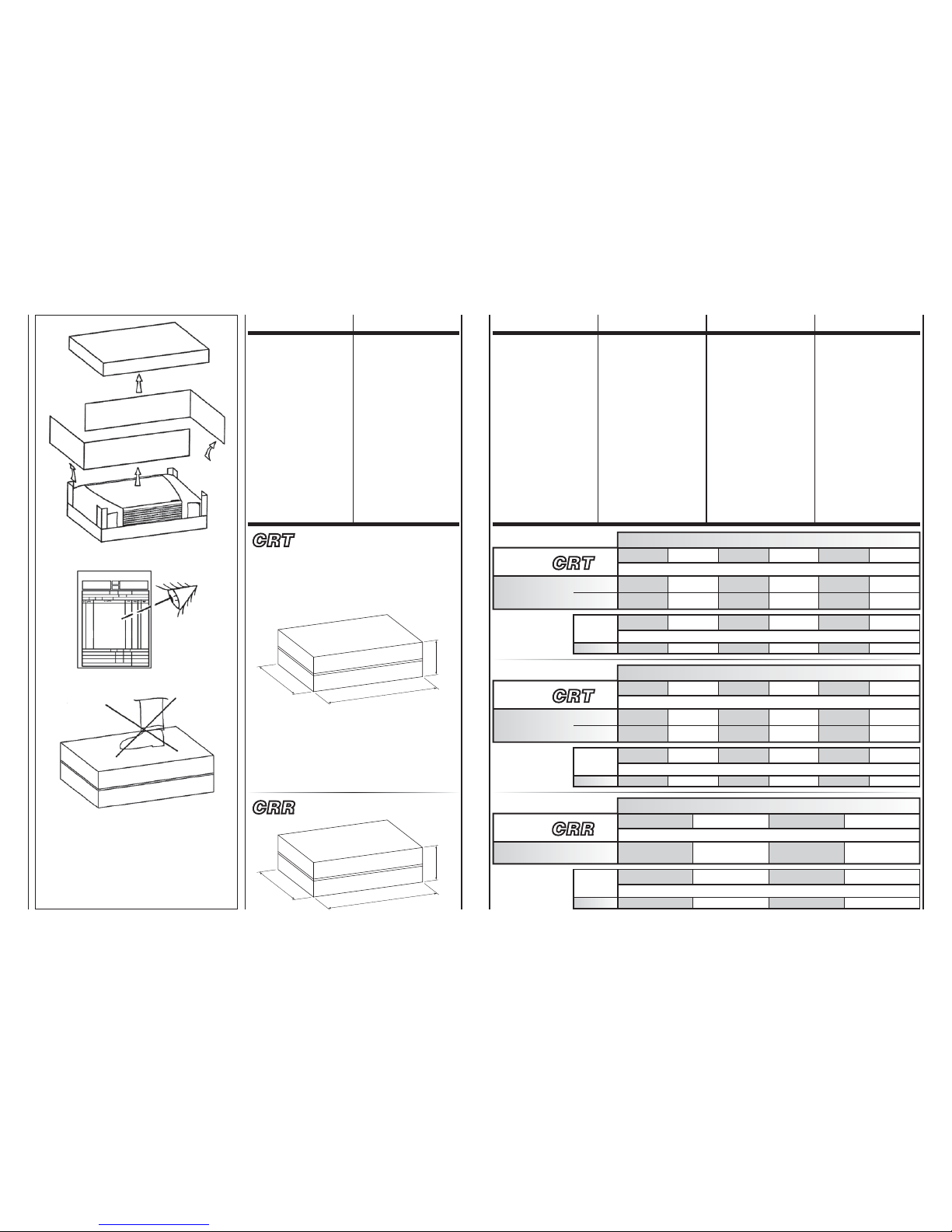
A bordo di ogni singola macchina
è applicata l’etichetta di identifica-
zione riportante i dati del costrut-
tore ed il tipo di macchina.
L’etichetta è posizionata sul lato
dei comandi elettrici, all’interno
dell’apparecchio.
Each unit is supplied with an
identification plate giving details
of the manufacturer and the type
of appliance.
The label is located inside the
appliance on the electric controls
side.
Une étiquette d’identification est
appliquée sur chaque machine; elle
indique les données du constructeur
et le type de machine.
Cette étiquette se trouve sur le
côté des commandes électriques,
à l’intérieur de l’appareil.
Jedes Gerät ist mit einem Typen-
schild gekennzeichnet, auf dem
die Daten des Herstellers und der
Typ des Geräts angegeben sind.
Das Schild befindet sich auf der
Seite der elektrischen Steuerungen,
im Geräteinnern.
Cada máquina lleva una placa de
identificación en la que figuran los
datos del fabricante y el tipo de
máquina de que se trata.
La etiqueta está emplazada en el
lado de los dispositivos de acciona-
miento eléctricos, dentro del aparato.
Aan boord van elk apparaat wordt
een identificatielabel aangebracht
met de gegevens van de fabrikant
en het type machine.
De label wordt aangebracht op de
zijkant van de elektrische bedieningen,
aan de binnenkant van het apparaat.
3 3A
I componenti principali sono:
MOBILETTO DI COPERTURA di
tipo misto in lamiera d’acciaio zin-
cata a caldo preverniciata e spalle
in materiale sintetico antiurto. È
facilmente smontabile per una com-
pleta accessibilità dell’apparecchio.
La griglia di mandata dell’aria, fa-
cente parte del mobiletto, è di tipo
reversibile ad alette fisse e posi-
zionato sulla parte superiore.
GRUPPO VENTILATORE
Costituito da ventilatore di tipo tan-
genziale, particolarmente silenzioso
con girante in alluminio bilanciata sta-
ticamente e dinamicamente, diretta-
mente calettata sull’albero motore.
MOTORE ELETTRICO
Di tipo monofase a 6 velocità (di
cui 3 collegate), montato su suppor-
ti elastici antivibranti e con conden-
satore permanentemente inserito,
protezione termica interna a riar-
mo automatico, grado di protezione
IP 20 e classe B.
BATTERIA
DI SCAMBIO TERMICO
È costruita con tubi di rame ed
alette in alluminio fissate ai tubi con
procedimento di mandrinatura mec-
canica. La batteria è dotata di 2 at-
tacchi Ø 1/2” gas femmina. I collet-
tori delle batterie sono corredati di
sfoghi d’aria e di scarichi d’acqua
Ø 1/8” gas. I Ventilconvettori CRT
possono essere corredati di bat-
teria addizionale (solo per riscal-
damento), con attacchi femmina
Ø 1/2” gas (versione 3 ranghi più 1;
per impianti a 4 tubi).
LAPOSIZIONE
DI SERIE DEGLI ATTACCHI
ÈASINISTRA,
GUARDANDO L’APPARECCHIO.
Se indicato nell’ordine, la posizio-
ne degli attacchi può essere spo-
stata a destra.
FILTRO di materiale sintetico rige-
nerabile.
BACINELLA
RACCOLTA CONDENSA in ma-
teriale plastico, realizzata a forma
di L e fissata alla struttura interna.
The main components are:
CASING
In prepainted hot galvanised sheet
steel with synthetic impact resistant
side panels. Easy to remove for
complete access to the unit.
The air discharge grid incorporated
in the top of the casing is reversible
with fixed louvres.
FAN ASSEMBLY
Consists of a particularly quiet
tangential fan. The aluminium fan
blades are statically and dynamically
balanced and are fixed directly to
the motor shaft.
ELECTRIC MOTOR
The motor is wired for single phase
and has six speeds (three connected)
with always-on capacitor. The motor
is fitted on sealed for life bearings
and is secured on anti-vibration and
self-lubricating mountings. Internal
thermal protection with automatic
reset, protection IP 20, class B.
HEAT
EXCHANGE COIL
Made with aluminium finned copper
tubes. The exchanger has two 1/2”
female gas connections. Coil headers
with air vents and water drain outlets
(1/8” dia. gas). The CRT units can
be fitted with a supplementary
exchanger (for heating only) with
1/2” dia. gas female connections
(3 row plus 1 version; for 4-tube
installations).
ASSTANDARD,
THE CONNECTIONS
ARE ON THE LEFT HAND SIDE
FACING THE UNIT.
The units can be supplied if specified
with the connections on the right
hand side.
Regenerable synthetic FILTER.
CONDENSATE
DRAIN PAN, plastic, L-shaped,
fixed to internal structure.
Les composants principaux sont:
CARROSSERIE de type mixte en
tôle d’acier zinguée à chaud pré-
peinte et panneaux latéraux en
matière synthétique antichoc. Elle
est facilement démontable, ce qui
offre une accessibilité totale à
l’appareil.
La grille de refoulement de l’air, qui
fait partie de la carrosserie, est du
type réversible à ailettes fixes et se
trouve sur la partie supérieure.
GROUPE VENTILATEUR
Composé d’un ventilateurs tangential
avec des pales équilibrées statique-
ment et dynamiquement directement
calé sur l’arbre du moteur.
MOTEUR ÉLECTRIQUE
De type monophasé à 6 vitesses
(dont 3 raccordées), monté sur
supports antivibratiles et avec con-
densateur permanent, protection
thermique à réarmement auto-
matique, protection IP 20 et classe B.
BATTERIE
D’ÉCHANGE THERMIQUE
Construite avec des tubes en cuivre
et des ailettes en aluminium fixées
aux tubes par dudgeonnage méca-
nique. La batterie est équipée de
deux raccords Ø 1/2” gaz femelle.
Les collecteurs des batteries sont
dotés de purgeurs d’air et de sorties
d’eau Ø 1/8” gaz. Les ventilo-con-
vecteurs CRT peuvent être équipés
d’une batterie supplémentaire (seule-
ment pour le chauffage), avec des
raccords femelle Ø 1/2” gaz (version
3 rangs plus 1; pour installations
à 4 tuyauteries).
LAPOSITION
STANDARD DES RACCORDS
EST ÀGAUCHE,
QUAND ON REGARDE L’APPAREIL.
Si precise, la position des raccords
peut-être à droite.
FILTRE en matière synthétique
régénérable.
BAC DE RECUPERATION
DES CONDENSATS, en matière
plastique, réalisé en forme de “L“
et fixé à la structure interne.
Das Gerät setzt sich hauptsächlich
aus folgenden Bauteilen zusammen:
GEHÄUSE aus feuerverzinktem und
vorlackiertem Stahlblech mit Seiten-
teilen aus stoßfestem Kunststoff. Das
Gehäuse kann vollständig abgenommen
werden, um ungehindert Zugang
zum Gerät zu haben.
Das Ausblasgitter mit festen Luft-
leitlamellen, das Teil des Gehäuses
ist, ist umsteckbar und befindet sich
auf der Geräteoberseite.
GEBLÄSE
Bestehend aus sehr geräuscharmen
tangential ventilator, statisch und
dynamisch ausgewuchtet Alluminium-
laufräden, welche direkt auf der Motor-
welle befestigt sind.
ELEKTROMOTOR
Einphasenmotor mit sechs Drehzahl-
stufen (drei davon werkseiting
angeschlossen), auf elastischen
Schwingungsdämpfern montiert
und mit permanent eingeschaltetem
Kondensator, Wärmeschutz mit auto-
matischer Rückstellung, Schutzart
IP 20, Klasse B.
WÄRMETAUSCHER-
BATTERIE
Bestehend aus Kupferrohren mit
maschinell aufgezogenen Aluminium-
lamellen. Die Wärmetauscher sind
mit zwei Anschlüssen mit Innen-
gewinde ø 1/2” Gas versehen. Die
Sammler der Wärmetauscher sind mit
Entlüftungsöffnungen und Wasserablass-
Anschlüssen ø 1/8” Gas versehen. Die
CRT Geräte können mit einem Zusatz-
Wärmetauscher (nur für Heizung) mit
Innengewinde-Anschlüssen ø 1/2” Gas
ausgestattet werden (Ausführung
3 plus 1 Reihe; für 4-Leiter-System).
SERIENMÄSSIG
BEFINDEN SICH DIE ANSCHLÜSSE
VON VORNE GESEHEN LINKS.
Auf Anfrage können die Anschlüsse
auf die rechte Seite sein verlegt
werden.
FILTER aus regenerierbarem
Synthetikmaterial.
An der Innenstruktur befestigte,
L-förmige KONDENSATWANNE
aus Kunststoff.
Los componentes principales son:
MUEBLE DE COBERTURA de tipo
mixto en plancha de acero zincada
en caliente prebarnizada y espaldas
en material sintético antichoque. Es
fácilmente desmontable para tener
acceso completo al aparato.
La rejilla de impulsión del aire, que
forma parte del mueble, es del tipo
reversible con aletas fijas y está
emplazada en la parte superior.
GRUPO VENTILADOR
Formado por 1 ventilador tangen-
cial particularmente silencioso, con
rodetes de aluminio equilibrados
estática y dinámicamente, encajado
directamente en el eje motor.
MOTOR ELÉCTRICO
El motor eléctrico es monofásico con
6 velocidades (de las cuales 3 rela-
cinadas), montado sobre soportes
elásticos amortiguadores de vibra-
ciones y con condensador perma-
nentemente activado, protección
térmica de rearme automático, grado
de protección IP 20 y clase B.
BATERÍA
DE INTERCAMBIO TÉRMICO
Se compone de tubos de cobre y
aletas en aluminio fijadas a los tu-
bos con un procedimiento de man-
drilado mecánico. La batería tiene
2 conexiones Ø 1/2” gas hembra.
Los colectores de las baterías tienen
alivios de aire y descargas de agua
Ø 1/8” gas. Los fan coils CRT pueden
venir equipados con batería adicio-
nal (solamente para la calefacción),
con conexiones hembra Ø 1/2” gas
(variante 3 filas más 1; para insta-
laciones con 4 tubos).
LAPOSICIÓN PREDETERMINADA
DE LAS CONEXIONES ES
EN LA PARTE IZQUIERDA MIRANDO
AL APARATO DESDE ENFRENTE.
A petición, es posible desplazar
a la derecha la posición de las
conexiones.
FILTRO en material sintético
regenerable.
BARDEJA
DE CONDENSADOS, en material
plástico, con forma de “L” y asegu-
rada a la estructura interna.
De voornaamste onderdelen zijn:
BEHUIZING
Van het gemengde type in warm-
verzinkte voorbeschilderde staalplaten.
Is gemakkelijk demonteerbaar voor
een complete toegankelijkheid van
het apparaat.
De luchtrooster maakt deel uit van
de behuizing, is omkeerbaar, voorzien
van vaste ribben en bevindt zich aan
de bovenzijde.
VENTILATORGROEP
Samengesteld door een tangentiele
ventilator, bijzonder geruisloos met
statisch en dynamisch uitgebalanceerde
schoepen in aluminium, rechtstreeks
bevestigd op de aandrijfas van de motor.
ELEKTRISCHE MOTOR
Eenfasige, met 6 snelheden (waarvan
3 aangesloten), gemonteerd op trilvrije
elastische dragers met ingebouwde
permanente condensator, thermische
beveiliging met automatische reset,
beschermingsdraad IP20 en classi-
ficatie B.
BATTERIJ
WARMTEWISSELING
Samengesteld uit koperen buizen
en aluminium ribben die met een
mechanisch procédé aan de buizen
bevestigd zijn. De batterij voorzien
van 2 vrouwelijke gasaansluitingen
van Ø 1/2” . De collectors van de
batterijen zijn uitgerust met lucht-
uitlaten en waterafvoerpijpen van
Ø 1/8” gas. De ventilatorconvectors
CRT kunnen voorzien worden van
een extra batterij, en vrouwelijke
gasaansluitingen van Ø 1/2” (versie
met 3 rangen plus 1; voor installaties
met 4 leidingen).
DESERIËLE POSITIE
VAN DE AANSLUITINGEN IS LINKS,
ALS MEN VÓÓR HET
APPARAAT STAAT.
Op verzoek, kunnen de aansluitingen
naar rechts worden verplaatst.
Herbruikbare FILTER in synthetisch
materiaal.
OPVANGBAK
CONDENSATIEWATER, uitgevoerd
in L-vorm en vastgemaakt aan de
binnenstructuur.
IDENTIFICAZIONE
MACCHINA
IDENTIFYING
THE APPLIANCE
IDENTIFICATION
DES MACHINES
KENNZEICHNUNG
DES GERÄTS
IDENTIFICACIÓN
DE LA MÁQUINA
IDENTIFICATIE
APPARAAT
t
or
i
d
s
fo
g
Ø
1
/
p
os
s
t
eri
a
m
/
i
d
a
m
Ø
1
/
p
er

600
260
Z
600
220
Y720 820 1035 1250
1234
4 4A
CRT MV / MO – MVB / IV – IO
TRASPORTO TRANSPORT TRANSPORT TRANSPORT TRANSPORTE TRANSPORT
L’apparecchio viene imballato in
scatole di cartone.
Una volta che l’apparecchio è
disinballato controllare che non
vi siano danni e che corrisponda
alla fornitura.
In caso di danni o di sigla dell’ap-
parecchio non corrispondente a
quanto ordinato, rivolgersi al pro-
prio rivenditore citando la serie e
il modello.
The appliance is supplied in card-
board packaging.
After unpacking the appliance, make
sure it is undamaged and corresponds
to the unit requested.
In the event of damage or if the
identification code does not
correspond to that ordered, contact
your dealer immediately, quoting
the series and model.
L’appareil est emballé dans des
boîtes en carton.
Après avoir déballé l’appareil, contrôler
qu’il n’a subi aucun dommage et
qu’il correspond bien à la fourniture.
En cas de dommages ou si le sigle
de l’appareil ne correspond pas à
ce qui a été commandé, s’adresser
au revendeur en indiquant la série
et le modèle.
Das Gerät wird in Kartons verpackt.
Kontrollieren Sie beim Auspacken
sofort, ob das Gerät unversehrt ist,
und ob es mit den Angaben in den
Versandpapieren übereinstimmt.
Falls Schäden festgestellt werden
sollten, oder wenn die Artikelnummer
nicht mit dem bestellten Gerät über-
einstimmt, wenden Sie sich bitte an
Ihren Händler. Geben Sie bei Rückfragen
immer Serie und Gerätemodell an.
El aparato viene embalado en caja
de cartón.
Cuando se desembala el aparato,
es preciso comprobar que no tenga
desperfectos y que se corresponda
con el suministro previsto.
En caso de daños o de sigla del
aparato no correspondiente con la
del pedido, dirigirse al revendedor
indicando la serie y el modelo.
Het apparaat wordt in een kartonnen
doos verpakt.
Eens het apparaat van zijn verpakking
ontdaan, controleert u de integriteit
en conformiteit van het apparaat.
In geval van beschadigingen, of
indien het apparaat niet overeenkomt
met de bestelling, wendt u zich tot
uw verkoper, met vermelding van
het serienummer en het model.
PESI
E DIMENSIONI
UNITÀ IMBALLATA
WEIGHTS
AND DIMENSIONS
PACKED UNIT
POIDS ET
DIMENSIONS DE
L’UNITE EMBALLEE
GEWICHT
UND DIMENSIONEN
VERPACKTES GERÄT
PESO
Y DIMENSIÓN
UNIDAD EMBALADO
GEWICHT
EN AFMETINGEN
VERPAKTE EENHEID
14
15
16
19
21
27
24
30
25
31
30
37
3
3+1
Ranghi
Rows
Rangs
Reihen
Filas
Rangen
123567
MV – MO – MVB
Peso - Weight - Poids - Gewicht - Peso - Gewicht (kg)
MOD. CRT
720 820 1035 1250 1250 1465
123567
Z
MOD.Dimensioni - Dimensions - Dimensions - Dimensionen - Dimensión - Afmetingen (mm)
10
11
15
17
19
25
22
28
23
29
27
34
3
3+1
Ranghi
Rows
Rangs
Reihen
Filas
Rangen
123567
IV – IO
Peso - Weight - Poids - Gewicht - Peso - Gewicht (kg)
MOD. CRT
720 820 820 1035 1035 1250
123567
Z
MOD.Dimensioni - Dimensions - Dimensions - Dimensionen - Dimensión - Afmetingen (mm)
CRR MV
Ranghi / Rows / Rangs
Reihen / Filas / Rangen
2
1234
MV
Peso - Weight - Poids - Gewicht - Peso - Gewicht (kg)
MOD. CRR
13 14 19 22
Y
MOD.Dimensioni - Dimensions - Dimensions - Dimensionen - Dimensión - Afmetingen (mm)

Dopo aver aperto e tolto l’imballo,
accertarsi che il contenuto sia quello
richiesto e che sia integro. In caso
contrario, rivolgersi al rivenditore
ove si è acquistato l’apparecchio.
I ventilconvettori sono stati studiati
per riscaldare e/o condizionare gli
ambienti e devono quindi essere
utilizzati solamente per questo. Si
esclude qualsiasi responsabilità per
i danni eventuali causati da un uso
improprio.
Questo libretto deve accompagna-
re sempre l’apparecchio in quanto
parte integrante dello stesso.
Ogni riparazione o manutenzione
dell’apparecchio deve essere ese-
guita da personale specializzato e
qualificato.
Non si risponde in caso di danni
provocati da modifiche o manomis-
sioni dell’apparecchio.
After removing the packaging, make
sure the contents are as requested
and not damaged. If this is not the
case, contact the dealer where you
bought the appliance.
The fan coils have been designed
for room heating and/or air conditioning
and must be used exclusively for that
purpose. We declines all responsibility
for damage caused by their improper
use.
This booklet is an integral part of
the appliance and must always
accompany the unit.
All repairs or maintenance must be
performed by qualified specialists.
We declines all responsibility for
damage caused by modifications
or tampering with the unit.
Après avoir ouvert et retiré l’em-
ballage, s’assurer que le contenu
est conforme et qu’il est en parfait
état. En cas contraire s’adresser au
revendeur où l’appareil a été acheté.
Les ventilo-convecteurs ont été conçus
pour chauffer et/ou climatiser les
pièces et ne doivent être destinés qu’à
cet usage. Il exclut toute responsable
en cas de dommages causés par
un emploi anormal.
Cette notice doit toujours accompa-
gner l’appareil car elle en fait partie
intégrante.
Toutes les réparations ou entretiens
de l’appareil doivent être effectués
par le SAV ou par un technicien
spécialisé.
On décline toute responsabilité en
cas de dommages provoqués par
des modifications ou altérations de
l’appareil.
Nach dem Auspacken kontrollieren,
ob der Inhalt der Bestellung entspricht
und unversehrt ist. Im gegenteiligen
Fall wenden Sie sich an Ihren Händler.
Die Klimakonvektoren wurden zur
Heizung und Klimatisierung von
Räumen entwickelt und dürfen folglich
ausschließlich zu diesem Zweck
verwendet werden. Die Firma haftet
nicht für eventuelle Schäden, die
durch den unzweckmäßigen Gebrauch
verursacht werden.
Diese Betriebsanleitung ist wesent-
licher Bestandteil des Gerätes und
muss folglich immer zusammen mit
diesem verwahrt werden.
Alle Reparaturen oder Wartung-
sarbeiten müssen durch Personal
der Firma oder andere fachlich
qualifizierte Techniker erfolgen.
Die Firma haftet nicht für solche
Schäden, die durch die Veränderung
oder die Manipulierung des Geräts
entstehen.
Después de haber retirado el em-
balaje, comprobar que el contenido
sea el solicitado y que esté intacto.
En caso contrario, dirigirse al esta-
blecimiento donde se ha comprado
el aparato.
Los fan coils se han estudiado para
calentar y/o acondicionar las habita-
ciones y no deben usarse para otro
fin. Declinamos cualquier respon-
sabilidad por los posibles daños
debidos a un uso inadecuado.
Este manual debe acompañar
siempre al aparato ya que forma
parte del mismo.
Todas las reparaciones o mante-
nimiento del aparato deberán ser
realizadas por personal especia-
lizado y cualificado.
No se hace responsable en caso
de daños provocados por modi-
ficaciones o manipulaciones del
aparato.
Na de verpakking te hebben
verwijderd, controleren of de inhoud
ervan correct en onbeschadigd is.
Is dit niet het geval, contact opnemen
met de verkoper of waar het apparaat
werd aangekocht.
De ventilatorconvectors werden
ontworpen voor de verwarming
en/of koeling van ruimten, en dienen
uitsluitend hiervoor te worden gebruikt.
Wij kunnen niet aansprakelijk worden
gesteld voor eventuele schade die
het gevolg is van een verkeerd
gebruik van het apparaat.
Deze handleiding dient het apparaat
steeds te vergezellen, omdat het
er wezenlijk deel van uitmaakt.
Reparaties of onderhoud van het
apparaat dienen uitgevoerd te
worden door gespecialiseerd en
opgeleid personeel.
Wij kunnen niet aansprakelijk worden
gesteld voor schade die voortvloeit
uit aangebrachte wijzigingen.
• Apparecchio.
• Libretto
di istruzioni e manutenzione.
• Appliance.
• Instruction
and maintenance manual.
• Appareil.
• Instructions
d’installation et d’entretien.
• Gerät.
• Gebrauchs-
und Wartungsanleitung.
• Aparato.
• Manual de instrucciones
y mantenimiento.
• Apparaat.
• Handleiding voor het gebruik
en het onderhoud.
NOTE
GENERALI
ALLA CONSEGNA
GENERAL
NOTES
ON DELIVERY
REMARQUES
GENERALES POUR
LA LIVRAISON
ALLGEMEINE
HINWEISE
ZUR LIEFERUNG
NOTAS
GENERALES
PARA LA ENTREGA
ALGEMEINE
OPMERKINGEN
BIJ DE LEVERING
5 5A
AVVERTENZE
GENERALI
GENERAL
WARNINGS GENERALITES
ALLGEMEINE
HINWEISE
ADVERTENCIAS
GENERALES
ALGEMENE
VOORSCHRIFTEN

6 6A
È vietato l’utilizzo del ventilconvet-
tore da parte di bambini o di per-
sone inabili e senza assistenza.
È pericoloso toccare l’apparecchio
avendo parti del corpo bagnate ed
i piedi nudi.
Non effettuare nessun tipo di inter-
vento o manutenzione senza aver
prima scollegato l’apparecchio dal-
l’alimentazione elettrica.
Non manomettere o modificare i
dispositivi di regolazione o sicu-
rezza senza essere autorizzati e
senza indicazioni.
Non torcere, staccare o tirare i
cavi elettrici che fuoriescono dal-
l’apparecchio anche se lo stesso
non è collegato all’alimentazione
elettrica.
Non gettare o spruzzare acqua
sull’apparecchio.
Non introdurre assolutamente nien-
te attraverso le griglie di aspirazio-
ne e mandata aria.
Non rimuovere nessun elemento
di protezione senza aver prima
scollegato l’apparecchio dall’ali-
mentazione elettrica.
Non gettare o lasciare il materiale
residuo dell’imballo alla portata dei
bambini perché potenziale causa
di pericolo.
Non installare in atmosfera esplo-
siva o corrosiva, in luoghi umidi,
all’aperto o in ambienti con molta
polvere.
Fan coils must never be used by
children or unfit persons without
supervision.
It is dangerous to touch the unit
with damp parts of the body and
bare feet.
Always unplug the unit from the
mains power supply before carrying
out any type of operation or
maintenance.
Never tamper with or modify
regulation and safety devices
without prior authorisation and
instructions.
Never twist, detach or pull power
cables, even when the unit is
unplugged from the mains power
supply.
Never throw or spray water on the
unit.
Never introduce foreign objects
through the air intake and discharge
grids.
Never remove protective elements
without first unplugging the unit
from the mains power supply.
Do not throw packaging material
away or leave it within reach of
children as it may represent a
hazard.
Do not install in explosive, corrosive
or damp environments, outdoors
or in very dusty rooms.
Le ventilo-convecteur ne doit pas
être utilisé par des enfants ou des
personnes inaptes non assitées.
Il est dangereux de toucher
l’appareil si on a des parties du
corps mouillées ou les pieds nus.
N’effectuer aucun intervention sur
l’appareil sans l’avoir débranché
au préalable.
Ne pas altérer ou modifier les
dispositifs de réglage ou de sécurité
sans autorisation et sans instructions.
Ne pas tordre, détacher ou tirer
les câbles électriques qui sortent
de l’appareil même si celui-ci est
débranché.
Ne pas jeter ou vaporiser de l’eau
sur l’appareil.
Ne rien introduire à travers les
grilles d’aspiration et de soufflage
de l’air.
N’enlever aucune protection sans
avoir au préalable débranché
l’appareil.
Ne pas jeter ou laisser l’emballage
à la portée des enfants car il peut
représenter un danger.
Ne pas installer l’appareil dans une
atmosphère explosive ou corrosive,
dans des lieux humides, dehors ou
dans des pièces où il y a beaucoup
de poussière.
Der Klimakonvektor darf weder von
Kindern, noch von Personen, die
nicht mit seiner Bedienung vertraut
sind, benutzt werden.
Das Gerät darf weder barfuß noch
mit nassen oder feuchten Körper-
teilen berührt werden.
Das Gerät darf erst gewartet werden,
nachdem die Spannungsversorgung
unterbrochen wurde.
Die Regel- und Sicherheitsein-
richtungen dürfen ohne vorherige
Genehmigung Firma und deren
Anleitung nicht verändert oder
manipuliert werden.
Die aus dem Gerät kommenden
Stromkabel dürfen nicht gezogen,
getrennt, verdreht werden, auch
dann nicht, wenn das Gerät nicht an
das Stromnetz angeschlossen ist.
Das Gerät darf nicht mit Wasser
in Berührung kommen.
Keine Gegenstände durch die Luft-
gitter stecken.
Die Schutzelemente dürfen erst
dann entfernt werden, nachdem die
Spannungsversorgung unterbrochen
wurde.
Das Verpackungsmaterial muss
vorschriftsmäßig entsorgt werden,
und darf nicht in die Reichweite
von Kindern gelangen, da es eine
potentielle Gefahrenquelle darstellt.
Das Gerät darf nicht in explosiver
oder korrosiver Atmosphäre, im
Freien oder in Räumen mit starker
Staubbelastung installiert werden.
Se prohibe el uso del fan coil a los
niños y a las personas incapaci-
tadas no asistidas.
Es peligroso tocar el aparato te-
niendo partes del cuerpo mojadas
y con los pies descalzos.
No efectuar ningún tipo de inter-
vención o mantenimiento sin antes
de haber desconectado el aparato
de la corriente eléctrica.
No manipular o modificar los dispo-
sitivos de regulación o de seguridad
sin la autorización y indicaciones.
No torcer, desconectar o tirar de
los cables eléctricos que salen del
aparato, aunque éste estuviera de-
sconectado de la corriente eléctrica.
No tirar o vaporizar agua sobre el
aparato.
No introducir absolutamente nada
a través de las rejillas de aspira-
ción y descarga de aire.
No retirar ningún elemento de pro-
tección sin antes haber desco-
nectado el aparato de la corriente
eléctrica.
No tirar o dejar al alcance de los
niños el material de embalaje ya
que es una fuente potencial de
peligro.
No instalar en una atmósfera
explosiva o corrosiva, en lugares
húmedos, al aire libre o en lugares
con mucho polvo.
De ventilatorconvector dient niet
te worden gebruikt door kinderen
of onbekwame personen, zonder
toezicht.
Het is gevaarlijk het apparaat aan
te raken wanneer delen van het
lichaam nat zijn of men op blote
voeten loopt.
Verricht geen handelingen of
onderhoud aan het apparaat
vooraleer dit werd losgekoppeld
van het elektriciteitsnet.
De regel- of veiligheidsinrichtingen
worden niet gehanteerd of gewijzigd
zonder toelating.
De stroomkabels die uit het appa-
raat steken, worden niet gekneld,
losgekoppeld of onder trekspanning
gebracht, zelfs wanneer het appa-
raat niet aangesloten is op het
elektriciteitsnet.
Zorg ervoor dat het apparaat niet
in contact komt met water.
Zorg ervoor dat niets door de
aanzuig- en luchtinlaatrooster kan
dringen.
Verwijder geen enkele beveiliging
alvorens het apparaat losgekoppeld
te hebben van het elektriciteitsnet.
Laat het verpakkingsmateriaal
niet rondslingeren of binnen het
bereik van kinderen, omdat het
gevaarlijk kan zijn.
Stel het apparaat niet op in een
explosieve of corrosieve omgeving,
op een vochtige plaats, buiten of
in ruimten met veel stof.
REGOLE
FONDAMENTALI
DI SICUREZZA
FUNDAMENTAL
SAFETY RULES
RÈGLES
FONDAMENTALES
DE SÉCURITÉ
GRUNDSÄTZLICHE
SICHERHEITS-
VORSCHRIFTEN
NORMAS
FUNDAMENTALES
DE SEGURIDAD
BELANGRIJKE
VEILIGHEIDS-
VOORSCHRIFTEN

7 7A
Prima di effettuare qualsiasi inter-
vento assicuratevi che:
1 -
Il ventilconvettore non sia sotto
tensione elettrica.
2 - Chiudere la valvola di alimen-
tazione dell’acqua della batte-
ria e lasciarla raffreddare.
3 -
Installare in prossimità dell’ap-
parecchio o degli apparecchi
in posizione facilmente acces-
sibile un interruttore di sicu-
rezza che tolga corrente alla
macchina.
Durante l’installazione, la manuten-
zione e la riparazione, per motivi di
sicurezza, è necessario attenersi
a quanto segue:
• Utilizzare
sempre guanti da lavoro.
• Non esporre
a gas infiammabili.
• Non posizionare
sulle griglie oggetti.
Assicurarsi
di collegare la messa a terra.
Nel caso di installazione di ventil
in versione MV o MVB senza co-
mando a bordo, fissare lo sportello
con una vite 2,2x9,5 mm.
Per ragioni di sicurezza è tassa-
tivo montare le chiusure inferiori
nel caso di installazioni di appa-
recchi MV senza piedi. Le chiusu-
re impediscono che si possa rag-
giungere con le mani parti interne
dei vani tecnici e parti sotto tensio-
ne. Il mancato montaggio di que-
ste chiusure è di grave pregiudizio
per la sicurezza delle persone.
Before carrying out any operation
on the appliance, make sure:
1 -
The unit is disconnected from
the electrical power supply.
2 - The coil water supply valve is
closed and the coil has cooled
down.
3 - Install a safety switch to turn
off current to the appliance in
an easily accessible position
near the unit or units.
During installation, maintenance and
repairs, for safety reasons, observe
the following precautions:
• Always use work gloves.
• Do not expose
to inflammable gas.
• Do not place objects
over the grids.
Make sure
the unit is earthed.
In case of installation of fan coil
version MV or MVB without onboard
control, fasten the control opening
with a 2.2 x 9.5 mm screw.
For safety reasons, the bottom
panels must be fitted when installing
MV version appliances without feet.
The panels prevent the parts inside
the technical compartment an the
live parts from being accessible to
the hands. Failure to fit these panels
represents a serious risk to personal
safety.
Avant d’effectuer toute intervention,
s’assurer que:
1 -
Le ventilo-convecteur n’est pas
sous tension électrique.
2 -
Fermer la vanne d’alimentation
de l’eau de la batterie et la
laisser refroidir.
3 -
Installer à proximité du ou des
appareils et dans une position
facilement accessible un inter-
rupteur de sécurité pour couper
le courant de la machine.
Pendant l’installation, l’entretien
et la réparation, pour des raisons
de sécurité, il est nécessaire de
respecter ce qui suit:
• Utiliser toujours
des gants de travail.
• Ne pas exposer
à des gaz inflammables.
• Ne placer aucun objet
sur les grilles.
S’assurer que la mise à la terre
a été effectuée.
En cas d’installation de ventil en
version MV ou MVB sans commande
à bord, fixer l’ouverture pour la
commande avec une vis 2,2 x 9,5mm.
Pour des raisons de sécurité il est
impératif de monter les protections
inférieures en cas d’installation
d’appareils MV sans pieds. Les
protections empêchent d’accéder
aux compartiments techniques et
aux parties sous tension. L’absence
de ces protections peut avoir de
graves conséquences sur la sécurité
des personnes.
Vor Durchführung irgendwelcher
Eingriffe:
1 -
Sicherstellen, dass der Gebläse-
konvektor nicht unter Spannung
steht.
2 - Das Wassereinlassventil der
Batterie schließen und abkühlen
lassen.
3 -
An einer gut zugänglichen Stelle
in der Nähe des Geräts bzw. der
Geräte einen Sicherheitsschalter
installieren, der die Stromzufuhr
zum Gerät unterbricht.
Aus Gründen der Sicherheit sind
während der Installation, Wartung
und Reparaturen, die folgenden
Vorschriften einzuhalten:
• Stets Arbeitshandschuhe
tragen.
• Keinen feuergefährlichen
Gasen aussetzen.
• Nichts auf die Ausblasgitter
stellen.
Vergewissern Sie sich, dass das
Gerät korrekt geerdet wird.
Bei Installation der Ventil-konvektoren
in der Ausführung MV oder MVB
ohne Steuerung die Klappe mit einer
Schraube zu 2,2 x 9,5mm befestigen.
Aus Sicherheitsgründen müssen
bei der Installation von Geräten MV
ohne Füße die unteren Verschlüsse
unbedingt montiert werden. Die
Verschlüsse verhindern den Zugriff
auf die Geräteinnenteile und die
unter Spannung stehenden Teile mit
den Händen. Wenn diese Verschlüsse
nicht montiert werden, ist die Personen-
sicherheit stark beeinträchtigt.
Antes de efectuar cualquier ope-
ración es preciso comprobar que:
1 - El fan coil no está alimentado
eléctricamente.
2 - Cerrar la válvula de alimenta-
ción del agua de la batería y
dejar que se enfríe.
3 -
Instalar cerca del aparato o de
los aparatos, en una posición
a la que se acceda fácilmente,
un interruptor de seguridad que
desconecte la alimentación de
la máquina.
Durante la instalación, el manteni-
miento y repación, por motivos de
seguridad, es necesario atenerse
a los siguiente:
• Usar siempre
guantes de trabajo.
• No exponer
a gases inflamables.
• No dejar objetos
sobre las rejillas.
Comprobar siempre que
esté conectada la toma de tierra.
En caso de instalar ventil en versión
MV o MVB sin mando a bordo, fijar
la apertura de comando con un tor-
nillo de 2,2 x 9,5 mm.
Por razones de seguridad es obli-
gatorio montar los cerramientos
inferiores en caso de instalaciones
de aparatos MV sin pies. Los cerra-
mientos impiden que se puedan
alcanzar con las manos las partes
internas de las aperturas técnicas
y las partes bajo tensión. No realizar
el montaje de estos cerramientos
supone un grave perjuicio para la
seguridad de las personas.
Alvorens u een handeling uitvoert aan
het apparaat, vergewis u ervan dat:
1 -
De ventilatorconvector niet onder
elektrische spanning staat.
2 - De watertoevoerklep van de
batterij gesloten is. Laat deze
laatste afkoelen.
3 - Installeer vlakbij het apparaat
of de apparaten een makkelijk
bereikbare noodschakelaar
die de stroomtoevoer naar de
machine onderbreekt.
Tijdens de installatie, het onderhoud
en de reparaties, is het uit veiligheids-
overwegingen noodzakelijk na te
leven wat volgt:
• Gebruik altijd
werkhandschoenen.
• Niet blootstellen
aan brandbare gassen.
• Geen voorwerpen
op de roosters plaatsen.
Zorg
voor een aardaansluiting.
In het geval van installatie van ventil in
de versie MV of MVB zonder bediening
aan boord, de klep vastmaken met een
schroef 2,2 x 9,5mm.
Om veiligheidsredenen is het
noodzakelijk om de onderste sluitingen
te monteren in het geval van installaties
van MV-apparaten zonder voetjes.
De sluitingen voorkomen dat de
technische onderdelen en onderdelen
die onder stroom staan van binnenin
met de handen aangeraakt kunnen
worden. Het niet monteren van deze
sluitingen brengt de veiligheid van
de personen ernstig in gevaar.
PRESCRIZIONI
DI SICUREZZA SAFETY RULES
CONSIGNES
DE SECURITE
SICHERHEITS-
VORSCHRIFTEN
PRESCRIPCIONES
DE SEGURIDAD
VEILIGHEIDS-
VOORSCHRIFTEN

8 8A
Per trasportare la macchina solle-
varla da soli (per pesi inferiori a
30 Kg) o con l’aiuto di un’altra per-
sona.
Sollevarla lentamente, facendo
attenzione che non cada.
Le ventole possono raggiungere
la velocità di 1000 g/min.
Non inserire oggetti nell’elettro-
ventilatore nè tantomeno le mani.
Non togliere le etichette di sicu-
rezza all’interno dell’apparecchio.
In caso di illeggibilità richiederne
la sostituzione.
When moving the appliance, lift it
by yourself (for weights of under
30 kg) or with the help of another
person.
Lift it slowly, taking care not to
drop it.
Fan blades may reach speeds of
up to 1000 revs/min.
Never introduce objects or the hand
into the fans.
Do not remove the safety labels
inside the appliance.
If you cannot read the labels, ask
for replacements.
Pour transporter la machine, la
soulever tout seul (pour des poids
inférieurs à 30 kg) ou avec l’aide
d’une autre personne.
La soulever lentement, en faisant
attention qu’elle ne tombe pas.
Les ventilateurs peuvent atteindre
la vitesse de 1000 tr/mn.
Ne pas introduire d’objets dans le
ventilateur, et surtout pas les mains.
Ne pas retirer les étiquettes de
sécurité à l’intérieur de l’appareil.
Si les étiquettes sont illisibles, en
demander d’autres exemplaires.
Für den Transport kann das Gerät
alleine (für Gewicht unter 30 kg)
oder zu zweit angehoben werden.
Langsam und vorsichtig anheben,
damit es nicht herabfällt.
Die Laufräder können eine Drehzahl
von 1.000 U/min. erreichen.
Stecken Sie keine Gegenstände in
den Ventilator, und greifen Sie erst
recht nicht mit den Händen hinein.
Die Sicherheitsetiketten im Geräte-
innern dürfen nicht entfernt werden.
Falls Sie unleserlich sind, müssen
sie ersetzt werden.
Para desplazar la máquina basta
una persona (para pesos inferiores
a los 30 Kg) o dos.
Levantarla despacio teniendo cui-
dado en no soltarla.
Los ventiladores pueden alcanzar
una velocidad de 1000 r.p.m.
No introducir objetos en el ventila-
dor ni tanto menos las manos.
No quitar las etiquetas de seguri-
dad presentes dentro del aparato.
Si se estropean hasta quedar ile-
gibles es preciso sustituirlas.
Voor het transport, heft u de machine
alleen (voor gewichten kleiner dan
30kg) of met de hulp van iemand
anders.
Hef de machine traag op, zonder
te laten vallen.
De propellers kunnen een snelheid
van 1000 t/min. halen.
Steek geen voorwerpen of handen
in de elektronventilator.
Verwijder de veiligheidslabels aan de
binnenkant van het apparaat niet.
Als de labels niet leesbaar zijn, laat
u ze vervangen.
ATTENZIONE!
NON TOGLIERE LA
PROTEZIONE
DEL CIRCUITO STAMPATO
DELLA SCHEDA
ELETTRONICA
DAL SUPPORTO COMANDI.
IMPORTANT!
DO NOT REMOVE
THE ELECTRICAL BOARD
PRINTED CIRCUIT
GUARD FROM
THE CONTROL UNIT
MOUNTING.
ATTENTION!
NE PAS RETIRER
LA PROTECTION
DU CIRCUIT IMPRIME
DE LA CARTE
ELECTRONIQUE
DU SUPPORT
DES COMMANDES.
ACHTUNG!
DIE SCHUTZABDECKUNG
DER GEDRUCKTEN
SCHALTUNG DER PLATINE
DARF NICHT
VON DER HALTERUNG
DER STEUERUNGEN
GENOMMEN WERDEN.
ATENCIÓN!
NO QUITAR LA PROTECCIÓN
DEL CIRCUITO IMPRESO
DA LA TARJETA
ELECTRÓNICA
DEL SOPORTE
DEL CONTROL.
OPGELET!
VERWIJDER
DE BEVEILIGING VAN HET
GEDRUKTE CIRCUIT
VAN DE ELEKTRONISCHE
SCHAKELING NIET
AN DE BEDIENINGSBASIS.
IN CASO DI SOSTITUZIONE
O PULIZIA DEL FILTRO
RICORDARSI SEMPRE
DI REINSERIRLO
PRIMA
DELL’AVVIAMENTO
DELL’APPARECCHIATURA.
IF THE FILTER
REQUIRES
REPLACING OR CLEANING,
ALWAYS MAKE SURE
IT IS REPOSITIONED
CORRECTLY BEFORE
STARTING THE UNIT.
EN CAS
DE REMPLACEMENT OU
DE NETTOYAGE DU FILTRE,
NE JAMAIS OUBLIER
DE LE REMETTRE
AVANT DE METTRE
L’APPAREIL EN MARCHE.
BEI ERSATZ ODER
REINIGUNG DES FILTERS
NICHT VERGESSEN, DEN
FILTER VOR DEM
ERNEUTEN EINSCHALTEN
DES GERÄTS WIEDER
EINZUBAUEN.
EN CASO DE SUSTITUCIÓN
O DE LIMPIEZA DEL FILTRO
ACORDARSE SIEMPRE
DE COLOCARLO DE NUEVO
EN SU SITIO ANTES
DE PONER EN MARCHA
EL APARATO.
ALS U DE FILTER
VERVANGT
OF SCHOONMAAKT,
PLAATST U HEM STEEDS
TERUG VOOR
U HET APPARAAT
IN WERKING STELT.
In caso di sostituzione di compo-
nenti richiedere sempre ricambi
originali.
In caso di installazioni in climi par-
ticolarmente freddi, svuotare l’im-
pianto idraulico in previsione di
lunghi periodi di fermo macchina.
Nel caso di installazione con ser-
randa di presa d’aria esterna fare
attenzione al gelo invernale che
può causare la rottura dei tubi del-
la batteria.
Always use original spare parts.
In particularly cold climates, if the
appliance is not to be used for long
periods, drain the hydraulic circuit.
If the installation is fitted with an
external air intake damper, make
sure the coil tubes are not damaged
by temperatures below freezing
point.
Si l’on doit remplacer des compo-
sants, demander toujours des pièces
de rechange originales.
En cas d’installation dans des climats
particulièrement froids, vidanger
l’installation hydraulique lorsqu’on
prévoit de longues périodes d’arrêt
de la machine.
En cas d’installation avec un volet
de prise d’air extérieur, faire attention
au gel en hiver, qui peut provoquer la
rupture des tubes de la batterie.
Verlangen Sie immer Originaler-
satzteile.
Bei Installation in einem besonders
kalten Klima muss der Wasser-
kreislauf entleert werden, wenn das
Gerät für längere Zeit nicht benutzt
wird.
Achtung bei Installation mit Zuluft-
klappe im Freien, durch winterlichen
Frost können die Rohre der Batterie
beschädigt werden.
En caso de sustitución de compo-
nentes, pedir siempre repuestos
originales.
En caso de instalación en climas
particularmente fríos, vaciar la
instalación hidráulica si se prevén
largos plazos de parada de la
máquina.
En caso de instalación con toma
de aire exterior tener cuidado con
el hielo que puede causar la rotura
de los tubos de la batería.
Bij de vervanging van onderdelen,
vraagt u steeds naar originele
wisselstukken.
Voor een installatie in een bijzondere
koude omgeving, ledigt u de
hydraulische installatie als u voorziet
dat de machine gedurende een
lange periode niet zal werken.
Voor een installatie met een externe
luchtklep, kijk uit voor wintervorst
die de buizen van de batterij kan
beschadigen.

I dati fondamentali relativi al ventil-
convettore e allo scambiatore di
calore sono i seguenti:
Ventilconvettore
e scambiatore di calore:
• Temperatura massima
del fluido termovettore:
max 85°C
• Temperatura minima
del fluido di raffreddamento:
min 5°C
• Pressione
di esercizio massima: 1000 kPa
• Tensione di alimentazione:
230V - 50Hz
• Consumo di energia elettrica:
vedi targhetta dati tecnici
I dati tecnici delle valvole con
azionatore termoelettrico sono i
seguenti:
Valvole con
azionatore termoelettrico:
•
Pressione di esercizio: 1000 kPa
• Tensione di alimentazione:
230V~50/60Hz
• Rating/protezione VA:
5 VA/IP 44
• Tempo di chiusura: 180 sec.
• Contenuto massimo
di glicole nell’acqua: 50%
Altri dati tecnici
Tutti gli altri dati tecnici importanti
(dimensioni, pesi, collegamenti, ru-
morosità, ecc.) vengono forniti in
altre parti del presente Manuale,
nella documentazione tecnica a
parte o nella proposta tecnica.
The basic specification of the fan
coil and heat exchanger is given
below:
Fan coil
and heat exchanger:
• Maximum
temperature
of heat vector fluid: 85°C
• Minimum
temperature
of refrigerant fluid: 5°C
• Maximum
working pressure: 1000 kPa
• Power supply voltage:
230V - 50Hz
• Electric energy consumption:
see technical data label
The technical specification of the
valves with thermoelectric actuator
is given below:
Valves with
thermoelectric actuator:
• Working pressure: 1000 kPa
• Power supply voltage:
230V~50/60Hz
• Rating/VA protection:
5 VA/IP 44
• Closing time: 180 sec.
• Maximum glycol content
in water: 50%
Other technical data
All other important technical data
(dimensions, weights, connections,
noise emissions, etc.) are given
elsewhere in this User Information
Manual, in the separate technical
documentation or in the technical
proposal.
Les caractéristiques fondamentales
du ventilo-convecteur et de l’échan-
geur de chaleur sont les suivantes:
Ventilo-convecteur
et échangeur de chaleur:
• Température maximale
du fluide caloporteur:
85°C maxi
• Température minimale
du fluide de refroidissement:
5°C mini
• Pression
de marche maximale: 1000 kPa
• Tension d’alimentation:
230V - 50Hz
• Consommation
d’énergie électrique: voir
plaquette données techniques
Les données techniques des
soupapes à actionneur thermo-
électrique sont les suivantes:
Vannes
à
commande thermoélectrique:
• Pression de marche: 1000 kPa
• Tension d’alimentation:
230V~50/60Hz
• Degré de protection: 5 VA/IP 44
• Temps de fermeture: 180 sec.
• Contenu maximal de glycol
dans l’eau: 50%
Autres données techniques
Toutes les autres caractéristiques
techniques importantes (dimen-
sions, poids, raccordements, bruit
etc.) sont indiquées dans d’autres
parties de ce livret, dans la docu-
mentation technique à part ou dans
la proposition technique.
Die wesentlichen Daten des Klima-
konvektors und der Wärmetauscher
sind die folgenden:
Klimakonvektor
und Wärmetauscher:
• Max. Temperatur
des Kältemediums: 85°C
• Min. Temperatur
der Kühlflüssigkeit: 5°C
• Max. Betriebsdruck: 1000 kPa
• Versorgungsspannung:
230V - 50Hz
• Energieverbrauch:
siehe Typenschild
Die technischen Daten der thermo-
elektrischen Ventile sind wie folgt:
Ventile mit
thermoelektrischer Steuerung:
• Betriebsdruck: 1000 kPa
• Versorgungsspannung:
230V~50/60 Hz
• Rating/Sicherung VA:
5 VA/IP 44
• Verschlusszeit: 180 Sek.
• Max. Glykolanteil
im Wasser: 50%
Weitere technische Daten
Alle anderen wichtigen technischen
Daten (Abmessungen, Gewichte,
Anschlüsse, Geräuschpegel, usw.)
sind an anderen Stellen dieses
Handbuchs, in der separaten tech-
nischen Dokumentation oder in den
Angebotsunterlagen enthalten.
Los datos fundamentales relativos
al ventilador convector y al intercam-
biador de calor son los siguientes:
Ventilador convector
e intercambiador de calor:
• Temperatura máxima
del fluido termovector:
máx. 85°C
• Temperatura mínima
del fluido de enfriamiento:
mín. 5°C
• Máxima
presión de ejercicio: 1000 kPa
• Tensiones de alimentación:
230V - 50Hz
• Consumo de energía eléctrica:
ver placa de datos técnicos
Los datos técnicos de las válvulas
con accionador termoeléctrico son
los siguientes:
Válvulas con
accionador termoeléctrico:
• Presión de ejercicio: 1000 kPa
• Tensión de alimentación:
230V~50/60Hz
• Rating/protección VA:
5 VA/IP 44
• Tiempo de cierre: 180 seg.
• Contenido máximo
de glicol en el agua: 50%
Otros datos técnicos
Todos los otros datos técncicos im-
portantes (eida, pesos, conexiones,
ruido, etc.) se dan en otras partes
del presente Manual, en la docu-
mentación técnica.
De belangrijke gegevens met
betrekking tot de ventilator-
convector en de warmtewisselaar:
Ventilator-convector
en warmtewisselaar:
• Maximumtemperatuur
Vloeistof Thermovector:
max. 85°C
• Minimumtemperatuur
koelvloeistof:
min. 5°C
•
Maximale bedrijfsdruk: 1000 kPa
• Voedingsspanning:
230V - 50Hz
• Elektrisch
energieverbruik: zie plaatje
met technische gegevens
De technische gegevens van de
kleppen met thermo-elektrische
inschakeling:
Kleppen met thermo-
elektrische inschakeling:
• Bedrijfsdruk: 1000 kPa
• Voedingsspanning:
230V~50/60Hz
• Rating/VA-bescherming:
5 VA/IP 44
• Sluitingstijd: 180 sec.
• Maximaal
glycolgehalte water: 50%
Andere technische gegevens
Alle andere belangrijke technische
gegevens (afmetingen, gewichten,
aansluitingen, lawaai, enz.) worden
geleverd in andere delen van de
Handleiding, in de technische
documentatie of door het technisch
personeel.
9 9A
LIMITI DI IMPIEGO OPERATING LIMITS LIMITES D’EMPLOI EINSATZGRENZEN LÍMITES DE USO GEBRUIKSLIMIETEN
SMALTIMENTO
Le parti di consumo e quelle sosti-
tuite vanno smaltite nel rispetto del-
la sicurezza e in conformità con le
norme di protezione ambientale.
WASTE DISPOSAL
Consumables and replaced parts
should be disposed of safely and
in accordance with environmental
protection legislation.
ÉLIMINATION ENTSORGUNG ELIMINACIÓN AFDANKING
Les consommables et les pièces
remplacées doivent être éliminés
en respectant les règles de sécu-
rité et les normes de protection de
l’environnement.
Verbrauchsteile und ersetzte Teile
müssen vorschriftsmäßig entsorgt
werden.
Las partes de consumo y las que
se sustituyen se eliminan respe-
tando la seguridad y de acuerdo
con las normas de protección del
medio ambiente.
De verbruiksonderdelen en vervangen
onderdelen worden afgedankt met
respect voor de veiligheidsvoorschriften
en overeenkomstig de milieuwetgeving.

Ø 1/2" F
M
37
O
N
T
Ø 15 ext.
B
H
230
IN
OUT
P
R
S
321
T
H
B
230
OUT
IN
Ø 15 ext.
Ø 1/2" F
600
260
Z
A
530
A
B
170
71 44 125 133
158 158C
60 60
A
530
630
A
B
170
100
158 158
71 44 125 133
C
100
60 60
MV
MO – MVB
ATTACCHI IDRAULICI - HYDRAULIC CONNECTIONS - WASSERANSCHLÜSSE
RACCORDS HYDRAULIQUES - CONEXIONES HIDRÁULICAS - HYDRAULISCHE AANSLUITINGEN
10 10A
CARATTERISTICHE
TECNICHE
TECHNICAL
CHARACTERISTIC
CARACTERISTIQUES
TECHNIQUES
TECHNISCHE
EIGENSCHAFTEN
CARACTERÍSTICAS
TÉCNICAS
TECHNISCHE
KARAKTERISTIEKEN
• Batteria a 3 ranghi
• 3 row heat exchanger
• Batterie à 3 rangs
• 3-Reihige Batterie
• Batería con 3 filas
• Batterij met 3 rangen
• Batteria addizionale
di riscaldamento
(1 rango)
• 1 row additional
heat exchanger
• Batterie additionnelle
de chauffage
(à 1 rang)
• Zusatzregister
für Heizleistung
(1-Reihige)
• Batería adicional
de calefacción
(con 1 fila)
• Extra batterij
voor verwarming (1 rij)
DIMENSIONI (mm) - DIMENSIONS (mm) - DIMENSIONS (mm)
DIMENSIONEN (mm) - DIMENSIÓN (mm) - AFMETINGEN (mm)
PESO (kg) - WEIGHT (kg) - POIDS (kg)
GEWICHT (kg) - PESO (kg) - GEWICHT (kg)
CONTENUTO ACQUA (Litri) - WATER CONTENTS (litres) - CONTENANCE EAU (l)
WASSERINHALT (Liter) - CONTENIDO AGUA (Litros) - WATERINHOUD (Liter)
ASSORBIMENTO MOTORE - MOTOR ABSORPTION - CONSOMMATION MOTEUR
LEISTUNGSAUFNAHME MOTOR - COMSUMO MOTOR - MOTORABSORPTIE
CRT
A
B
C
H
M
N
O
P
R
S
T
Z
670
225
354
205
145
260
460
185
105
475
55
720
770
225
454
205
145
260
460
185
105
475
55
820
985
225
669
205
145
260
460
185
105
475
55
1035
1200
225
884
205
145
260
460
185
105
475
55
1250
1200
225
884
205
145
260
460
185
105
475
55
1250
1415
225
1099
205
145
260
460
185
105
475
55
1465
123567
MOD.
3
3+1
Ranghi
Rows
Rangs
Reihen
Filas
Rangen
123567123567
14
15
16
19
21
27
24
30
25
31
30
37
13
14
14
17
18
24
21
27
22
28
26
33
Unità imballata - Packed unit
Unité emballée - Verpackung des Gerätes
Unidad embalada - Verpakte eenheid
MOD.
Unità non imballata - Unpacked unit
Unité seule - Unverpackung des Gerätes
Unidad sin embalar - Eenheid zonder verpakking
123567
0,5
0,2
0,6
0,2
0,9
0,3
1,3
0,4
1,6
0,5
1,7
0,5
3
+1
Ranghi
Rows
Rangs
Reihen
Filas
Rangen
MOD.
123567
23
0,099
25
0,113
31
0,150
46
0,202
60
0,263
72
0,317
W
A
MOD.
230/1 50Hz
Piedini non inclusi (accessorio)
Feet optional extra
Pieds non compris (en option)
Füße nicht im Preis enthalten (Zubehör)
Pies de apoyo no incluidos (accesorio)
Voeten niet inbegrepen (optioneel)

Ø 1/2" F
M
37
O
N
U
Ø 15 ext.
G
H
230
IN
OUT
P
R
S
321
U
H
G
230
OUT
IN
Ø 15 ext.
Ø 1/2" F
123567
D
E
F
G
H
M
N
O
P
R
S
U
Y
374
330
354
218
205
145
260
460
185
105
475
65
720
474
430
454
218
205
145
260
460
185
105
475
65
820
689
645
669
218
205
145
260
460
185
105
475
65
820
904
860
884
218
205
145
260
460
185
105
475
65
1035
904
860
884
218
205
145
260
460
185
105
475
65
1035
1119
1075
1099
218
205
145
260
460
185
105
475
65
1250
MOD.
3
3+1
Ranghi
Rows
Rangs
Reihen
Filas
Rangen
123567123567
10
11
15
17
19
25
22
28
23
29
27
34
9
10
13
16
18
23
21
26
22
27
25
31
Unità imballata - Packed unit
Unité emballée - Verpackung des Gerätes
Unidad embalada - Verpakte eenheid
MOD.
Unità non imballata - Unpacked unit
Unité seule - Unverpackung des Gerätes
Unidad sin embalar - Eenheid zonder verpakking
123567
0,5
0,2
0,6
0,2
0,9
0,3
1,3
0,4
1,6
0,5
1,7
0,5
3
+1
Ranghi
Rows
Rangs
Reihen
Filas
Rangen
MOD.
123567
23
0,099
25
0,113
31
0,150
46
0,202
60
0,263
72
0,317
W
A
MOD.
230/1 50Hz
133 125
44
71
F150 10
G
H
Ø 15 ext.
230
153
17 119*
D
E*
12 12
G
H
Ø 15 ext.
230
153
17 119
*
71 44 125 133
F10
D
E*
12 12
511
D29
22 22
88
100
12 12
11 11A
IV – IO
Installazione Verticale - Vertical Installation
Installation Vertical - Vertikal Installiert
Instalación Vertical - Verticale Installatie
IV – IO
Installazione Orizzontale - Horizontal Installation
Installation Horizontal - Horizontal Installiert
Instalación Horizontal - Horizontale Installatie
ATTACCHI IDRAULICI - HYDRAULIC CONNECTIONS - WASSERANSCHLÜSSE
RACCORDS HYDRAULIQUES - CONEXIONES HIDRÁULICAS - HYDRAULISCHE AANSLUITINGEN
CARATTERISTICHE
TECNICHE
TECHNICAL
CHARACTERISTIC
CARACTERISTIQUES
TECHNIQUES
TECHNISCHE
EIGENSCHAFTEN
CARACTERÍSTICAS
TÉCNICAS
TECHNISCHE
KARAKTERISTIEKEN
• Batteria a 3 ranghi
• 3 row heat exchanger
• Batterie à 3 rangs
• 3-Reihige Batterie
• Batería con 3 filas
• Batterij met 3 rangen
• Batteria addizionale
di riscaldamento
(1 rango)
• 1 row additional
heat exchanger
• Batterie additionnelle
de chauffage
(à 1 rang)
• Zusatzregister
für Heizleistung
(1-Reihige)
• Batería adicional
de calefacción
(con 1 fila)
• Extra batterij
voor verwarming (1 rij)
600
260
Y
DIMENSIONI (mm) - DIMENSIONS (mm) - DIMENSIONS (mm)
DIMENSIONEN (mm) - DIMENSIÓN (mm) - AFMETINGEN (mm)
Sezione di mandata (E x119)
Outlet section (E x119)
Section de soufflage (E x119)
Ausblaseinheit (E x119)
Sección de impulsión (E x119)
Afmetingen uitlaat (E x119)
*
Vaschetta raccolta condensa (optional) - Condensate tray (optional)
Kondensatwanne (optional) - Bac à condensats (option)
Bandeja de recogida condensacion (opción) - Opvangbak condenswater (optioneel)
CRT
PESO (kg) - WEIGHT (kg) - POIDS (kg)
GEWICHT (kg) - PESO (kg) - GEWICHT (kg)
CONTENUTO ACQUA (Litri) - WATER CONTENTS (litres) - CONTENANCE EAU (l)
WASSERINHALT (Liter) - CONTENIDO AGUA (Litros) - WATERINHOUD (Liter)
ASSORBIMENTO MOTORE - MOTOR ABSORPTION - CONSOMMATION MOTEUR
LEISTUNGSAUFNAHME MOTOR - COMSUMO MOTOR - MOTORABSORPTIE

143
45
475
273
225
163
183
Ø 1/2" F
Ø 15 ext.
IN
OUT
670
354
720
A
C
Z
770
454
820
985
669
1035
1200
884
1250
1
MOD.234
1
28
0,127
W
A
MOD.
230/1 50Hz
2
27
0,122
3
31
0,14
4
36
0,163
0,4 0,5 0,8 1,1
1
MOD.234
1234
13 14 19 22
1234
12 13 18 20
Unità imballata - Packed unit
Unité emballée - Verpackung des Gerätes
Unidad embalada - Verpakte eenheid
MOD.
Unità non imballata - Unpacked unit
Unité seule - Unverpackung des Gerätes
Unidad sin embalar - Eenheid zonder verpakking
A
530
630
A 158 158
71 44 125 133
C
100
100
100 (min.)
60 60
12 12A
ATTACCHI IDRAULICI - HYDRAULIC CONNECTIONS - WASSERANSCHLÜSSE
RACCORDS HYDRAULIQUES - CONEXIONES HIDRÁULICAS - HYDRAULISCHE AANSLUITINGEN
CARATTERISTICHE
TECNICHE
TECHNICAL
CHARACTERISTIC
CARACTERISTIQUES
TECHNIQUES
TECHNISCHE
EIGENSCHAFTEN
CARACTERÍSTICAS
TÉCNICAS
TECHNISCHE
KARAKTERISTIEKEN
600
220
Z
DIMENSIONI (mm) - DIMENSIONS (mm) - DIMENSIONS (mm)
DIMENSIONEN (mm) - DIMENSIÓN (mm) - AFMETINGEN (mm)
CRR
PESO (kg) - WEIGHT (kg) - POIDS (kg)
GEWICHT (kg) - PESO (kg) - GEWICHT (kg)
CONTENUTO ACQUA (Litri) - WATER CONTENTS (litres) - CONTENANCE EAU (l)
WASSERINHALT (Liter) - CONTENIDO AGUA (Litros) - WATERINHOUD (Liter)
ASSORBIMENTO MOTORE - MOTOR ABSORPTION - CONSOMMATION MOTEUR
LEISTUNGSAUFNAHME MOTOR - COMSUMO MOTOR - MOTORABSORPTIE
MV
Piedini non inclusi (accessorio)
Feet optional extra
Pieds non compris (en option)
Füße nicht im Preis enthalten (Zubehör)
Pies de apoyo no incluidos (accesorio)
Voeten niet inbegrepen (optioneel)
Batteria a 2 ranghi / 2 row heat exchanger / Batterie à 2 rangs / 2-Reihige Batterie / Batería con 2 filas / Batterij met 2 rangen

13 13A
INSTALLAZIONE
MECCANICA
Installare l’apparecchio in una po-
sizione tale da non compromet-
tere l’aspirazione dell’aria (vedi
illustrazione).
Nell’installazione dei ventilconvet-
tori a soffitto si consiglia di tener
ben presente il possibile problema
di stratificazione dell’aria; ricordia-
mo inoltre che le griglie di manda-
ta devono essere posizionate in
modo che la direzione del flusso
d’aria sia verso il basso.
Fissare la struttura del ventil-con-
vettore; MV-MVB-IV alla parete,
MO-IO al soffitto.
In corrispondenza delle asole rica-
vate sulla stessa posizionare 4
tasselli (viti consigliate M8).
Per l’installazione contro vetrata
o in qualsiasi altra posizione dove
non esista una parete, è possibile
richiedere staffe per il fissaggio a
pavimento.
Versioni MV-MVB-MO; coprire la
struttura con il mobile e fissarlo
alla struttura con le viti fornite a
corredo.
Inserire il filtro aria nelle sue guide
e bloccare il profilo portafiltro.
Versioni MV senza piedini - chiu-
sura inferiore - (pannello) acces-
sorio indispensabile per impedire
il raggiungimento delle parti interne
dei vani tecnici.
MECHANICAL
INSTALLATION
When positioning the appliance,
make sure the air intakes are free
from obstructions (see illustration).
When installing the fan coils on the
ceiling, keep in mind the possible
problem of stratification of the air;
it should also be remembered that
the outlet grills must be positioned
so that the air flows downwards.
Fix the frame of the fan coil to the
wall (models MV, MVB and IV) or
ceiling (models MO, IO).
Position the four anchors (M8 screws
are recommended) in correspondence
to the four slits in the frame.
To install against a glazed surface
or in other position where there is
no wall, brackets can be used to
fix the unit to the floor.
In versions MV, MVB and MO, fit
the casing over the frame and fix
using the screws supplied.
Insert the air filter into the guides
and lock the filter holder strip in
place.
Version MV without feet - bottom
panel - an indispensable accessory
to prevent access to parts inside
the technical compartments.
INSTALLATION
MECANIQUE
MECHANISCHE
INSTALLATION
INSTALACIÓN
MECÁNICA
MECHANISCHE
INSTALLATIE
Installer l’appareil dans une position
n’empêchant pas l’aspiration de l’air
(cf. illustration).
Lorsqu’on installe des ventilo-con-
vecteurs au plafond il est conseillé
de prendre en compte le problème
possible de stratification de l’air;
nous rappelons en outre que les
grilles de soufflage doivent être
placées de façon à ce que le flux
d’air soit dirigé vers le bas.
Fixer la structure du ventilo-con-
vecteur; celle des MV-MVB-IV à la
paroi et celle des MO-IO au plafond.
Positionner, au niveau des trous
oblongs pratiqués dans la structure,
quatre chevilles à expansion (vis
conseillées M8).
Pour l’installation contre une baie
vitrée ou dans une quelconque
autre position où il existe pas de
paroi, on peut demander des pattes
pour la fixation au sol.
Versions MV-MVB-MO: couvrir la
structure avec la carrosserie en
fixant cette dernière à la structure,
avec les vis fournies de série.
Insérer le filtre à air dans ses guides
et bloquer le profilé porte-filtre.
Version MV sans pieds - fenneture
inférieure - accessoire indispensable
pour empêcher d’atteindre les parties
intérieures des compartiments tech-
niques.
Das Gerät muss so installiert werden,
dass die Luftansaugung nicht beein-
trächtigt wird (siehe Darstellung).
Bei der Deckeninstallation von
Klimakonvektoren sollte unbedingt
das potentielle Problem der Luft-
stratifikation berücksichtigt werden;
außerdem erinnern wir daran, dass
die Ausblasgitter so positioniert
sein müssen, dass der Luftstrom
nach unten gerichtet ist.
Die Struktur des Gebläsekonvektors
MV-MVB-IV an der Wand, bzw.
MO-IO an der Decke befestigen.
An den Schlitzen 4 Dübel anbringen
(empfohlene Schrauben M8).
Für die Installation gegen eine
verglaste Fläche oder in einer
sonstigen Stellung, in der keine
Wand vorhanden ist, können Bügel
für die Befestigung am Boden
angefordert werden.
Ausführungen MV-MVB-MO: die
Gerätestruktur mit dem Gehäuse
abdecken. Das Gehäuse mit den
mitgelieferten Schrauben an der
Struktur befestigen.
Den Luftfilter in seine Führungen
einschieben und das Filter-Halteprofil
befestigen.
Version MV ohne Füße - mit unterem
Verschluss - ein unerlässliches
Zubehör, um den Zugriff auf die
inneren Komponenten zu verhindern.
Instalar el aparato en una posición
tal que no se impida la aspiración
del aire (ver dibujo).
En la instalación de los ventilado-
res convectores de techo se reco-
mienda tener muy presente el po-
sible problema de estratificación
del aire; además recordamos que
las rejillas de impulsión tienen que
colocarse de modo que la dirección
del flujo de aire sea hacia abajo.
Asegurar la estructura del fan coil;
MV-MVB-IV a la pared, MO-IO al
techo.
En correspondencia con las ranuras
que lleva colocar 4 tacos de expan-
sión (tornillos aconsejados M8).
Para la instalación contra crista-
leras o en cualquier otra posición
donde no haya una pared, es po-
sible solicitar unos estribos para
la sujeción al suelo.
Variantes MV-MVB-MO; cubrir la
estructura con el mueble y asegu-
rarlo a la estructura con los tornillos
incluidos en el suministro.
Introducir el filtro del aire en sus
guías correspondientes y bloquear
el perfil porta-filtro.
Versiones MV sin pies - cierre
inferior - accesorio indispensable
para impedir alcanzar las partes
internas de las aperturas técnicas.
Installeer het apparaat in een positie
die de luchtaanvoer niet in het
gedrang brengt (zie illustratie).
Bij de installatie van plafond-
ventilator-convectors is het
aangeraden rekening te houden met
het probleem van luchtstratificatie;
wij herinneren er u tevens aan dat
de luchtroosters op die manier
geplaatst moeten worden, dat de
luchtstroom naar onder is gericht.
Bevestig de structuur van de ventilator-
convector; MV-MVB-IV aan de wand,
MO-IO aan het plafond.
Steek 4 pluggen in de gaten
aangebracht in de structuur
(aanbevolen schroeven M8).
Voor een installatie aan een
glaswand ofin een andere positie
waar geen wand aanwezig is, zijn
krammen beschikbaar voor de
bevestiging aan de vloer.
Versies MV-MVB-MO; bedek de
structuur met de behuizing en
bevestig deze aan de structuur met
behulp van de bijgeleverde schroeven.
Schuif de luchtfilter in zijn geleiders
en blokkeer het profiel van de
filterhouder.
Versie MV zonder voetjes - onderste
sluiting - (paneel) onmisbaar
accessoire om het bereiken van
interne delen in de technische
ruimtes te voorkomen.
ATTENZIONE!
INSTALLARE
L’APPARECCHIO SEMPRE
IN LEGGERA PENDENZA
8mm VERSO IL LATO
DI SCARICO CONDENSA.
WARNING!
ALWAYS INSTALL
THE UNIT
WITH A SLOPE
OF ABOUT 8mm TOWARDS
THE CONDENSATE
DRAIN SIDE.
ATTENTION!
INSTALLER
TOUJOURS L’APPAREIL
AVEC UNE LEGERE PENTE
DE 8mm VERS
LE COTE D’EVACUATION
DES CONDENSATS.
ACHTUNG!
DAS GERÄT MUSS IMMER
IN LEICHTER (8 mm)
NEIGUNG IN RICHTUNG
KONDENSATAUSLASS
INSTALLIERT WERDEN.
ATENCIÓN!
INSTALAR EL APARATO
SIEMPRE CON
UNA LIGERA PENDIENTE
DE 8mm HACIA EL LADO
DE DESCARGA
DEL CONDENSADO.
OPGELET!
INSTALLEER HET APPARAAT
STEEDS MET EEN LICHTE
HELLING VAN 8 mm NAAR
DE ZIJDE WAAR
HET CONDENSATIEVOCHT
WORDT AFGEVOERD.
È possibile installare l’apparecchio
con qualsiasi altro mezzo ritenuto
idoneo dall’installatore; purchè
conforme alle norme vigenti.
The unit can be installed using any
other method considered appropriate
by the installer, providing it is in
accordance with current legislation.
L’installeur pourra installer l’appareil
avec n’importe quel autre moyen
jugé approprié, à condition qu’il soit
conforme aux normes en vigueur.
Das Gerät kann mit jedem anderen,
vom Installateur für zweckmäßig
erachteten Mittel installiert werden,
jedoch immer unter der Voraussetzung,
dass die Installation den einschlägigen
Bestimmungen entspricht.
Es posible instalar el aparato con
cualquier otro medio considerado
adecuado por el instalador; siem-
pre y cuando cumpla con las nor-
mas vigentes.
Het is mogelijk het apparaat te
installeren met om het even welk
instrument dat door de monteur
geschikt wordt geacht, mits naleving
van de van kracht zijnde normen.
Per un corretto funzionamento del-
l’unità CRT versione IV-IO, non
connettere nessun canale in aspi-
razione e rispettare le dimensioni
suggerite per la griglia di ripresa.
For best operation of CRT IV-IO
units don’t connect any duct on the
return side and respect the minimum
suggested dimension of the air intake
grid.
Pour un fonctionnement optimum
des CRT IV-IO, ne pas gainer la
reprise et bien respecter les dimensions
minimum de la grille de reprise.
Für den korrekten Betrieb des Geräts
CRT Version IV-IO darf saugseitig
kein Kanal angeschlossen werden
und müssen die für das Ansauggitter
empfohlenen Abmessungen ein-
gehalten werden.
Para un correcto funcionamiento
de la unidad CRT versión IV-IO,
no conecte ningún canal en aspi-
ración y respete las dimensiones
sugeridas por la rejilla de toma.
Voor een correcte werking van de CRT
unit in de versie IV-IO, mag geen enkel
kanaal op de inlaat aangesloten
worden en moeten de geadviseerde
maten voor het luchtinlaatrooster
in acht genomen worden.

14 14A
COLLEGAMENTO
IDRAULICO
HYDRAULIC
CONNECTIONS
RACCORDEMENT
HYDRAULIQUE
WASSERANSCHLUSS
ENLACE
HIDRÁULICO
HYDRAULISCHE
AANSLUITING
PRESSIONE MASSIMA
DI ESERCIZIO: 1000 kPa.
MAXIMUM WORKING
PRESSURE: 1000 kPa.
PRESSION MAXI
DE SERVICE: 1000 kPa.
MAXIMALE
BETRIEBSDRUCK: 1000 kPa.
PRESIÓN MÁXIMA
DE OPERACIÓN: 1000 kPa.
MAXIMALE
BEDRIJFSDRUK: 1000 kPa.
USARE SEMPRE
CHIAVE E CONTROCHIAVE
PER L’ALLACCIAMENTO
DELLA BATTERIA
ALLE TUBAZIONI.
ALWAYS USE
TWO SPANNERS
TO CONNECT
THE HEAT EXCHANGER
TO THE PIPES.
UTILISER TOUJOURS
UNE CLE
ET UNE CONTRE-CLE
POUR LE RACCORDEMENT
DE LA BATTERIE
AUX TUYAUTERIES.
FÜR DEN ANSCHLUSS
DER BATTERIE
AN DIE ROHRLEITUNGEN
IMMER SCHLÜSSEL
UND GEGENSCHLÜSSEL
BENUTZEN.
USAR SIEMPRE
LLAVE Y CONTRALLAVE
PARA ENLAZAR
LA BATERÍA
A LAS TUBERÍAS.
GEBRUIK
STEEDS SLEUTELS
EN TEGENSLEUTELS
OM DE BATTERIJ
TE VERBINDEN
MET DE BUIZEN.
PREVEDERE SEMPRE
UNA VALVOLA
DI INTERCETTAZIONE
DEL FLUSSO IDRAULICO.
ALWAYS
FIT A GATE VALVE
IN THE WATER CIRCUIT.
PREVOIR TOUJOURS
UNE VANNE D’ARRET
DU FLUX HYDRAULIQUE.
IMMER EIN SPERRVENTIL
DES WASSERFLUSSES
INSTALLIEREN.
PREVER SIEMPRE
UNA VÁLVULA
DE ABRE-CIERRE
DEL FLUJO HIDRÁULICO
VOORZIE STEEDS EEN
RETOURKLEP.
NON È POSSIBILE
INVERTIRE
IL LATO ATTACCHI
IN CANTIERE, IN QUANTO
LO SPOSTAMENTO
DEL GRUPPO MOTORE
DAL LATO OPPOSTO
INVERTIREBBE
IL SENSO DI ROTAZIONE
DELLA VENTOLA.
IL LATO ATTACCHI
VA SPECIFICATO
ALL’ATTO DELL’ORDINE.
AT THE INSTALLATION SITE
IT IS IMPOSSIBLE
TO CHANGETHE SIDE
OF THE CONNECTIONS,
SINCE THE MOVE OF
THE MOTOR GROUP TO
THE OPPOSITE SIDE
WOULD RESULT IN AN
INVERSION OF THE SENSE
OF ROTATION OF THE FAN.
THE SIDE OF THE
CONNECTIONS HAS TO BE
SPECIFIED ALREADY AT
THE TIME OF THE ORDER.
IL N’EST PAS POSSIBLE
D’INVERSER LE CÔTÉ
DES RACCORDS SUR
LE LIEU D’INSTALLATION
DE L’APPAREIL PARCE
QUE LE DÉPLACEMENT
DU MOTEUR
SUR LE CÔTÉ OPPOSÉ
CAUSERAIT L’INVERSION
DU SENS DE ROTATION
DE L’HÉLICE. LE CÔTÉ
DES RACCORD DOIT ÊTRE
SPÉCIFIÉ Á
LA COMMANDE.
AM INSTALLATIONSORT
KANN DIE ANSCHLUßSEITE
NICHT MEHR GEÄNDERT
WERDEN, WEIL DURCH
DAS VERLEGEN DER
MOTORGRUPPE AUF DIE
GEGENÜBERLIEGENDE
SEITE DIE DREHRICHTUNG
DES LÜFTERS UMGEKEHRT
WÜRDE. DAHER MUß
DIE ANSCHUßSEITE BEREITS
BEI AUFTRAGSERTEILUNG
FESTGELEGT WERDEN.
NO ES POSIBLE
INVERTIR EL LADO
DE LOS ENLACESYA QUE
EL DESPLAZAMIENTO
DEL GRUPO MOTOR
DEL LADO APUESTO
INVERTIRÍA EL SENTIDO
DE ROTACIÓN
DE LA TURBINA.
EL LADO DE LOS ENLACES
HAY QUE ESPEFICARLO
AL MOMENTO DEL PEDIDO.
HET IS NIET MOGELIJK
DE AANSLUITINGEN
VAN ZIJDE TE VERANDEREN
TIJDENS HET MONTEREN,
DAAR DE VERPLAATSING
VAN HET MOTORBLOK
AAN DE ANDERE ZIJDE,
HET VENTIEL IN DE
TEGENGESTELDE RICHTING
ZOU DOEN DRAAIEN.
DE AANSLUITINGSZIJDE
MOET VERMELD WORDEN
BIJ DE BESTELLING.
ATTENZIONE!
È CONSIGLIATO SIFONARE
LO SCARICO
DELLA CONDENSA,
INSTALLARE
IL TUBO
DI SCARICO CONDENSA
CON UNA PENDENZA
DI ALMENO 3 cm/metro.
IMPORTANT!
YOU ARE RECOMMENDED
TO FIT A SIPHON
ON THE CONDENSATE
DRAIN. INSTALL
A CONDENSATE
DRAIN PIPE
WITH A SLOPE OF
AT LEAST 3 cm/metre.
ATTENTION!
IL EST CONSEILLE DE
SIPHONER L’EVACUATION
DES CONDENSATS
ET D’INSTALLER LE TUYAU
D’EVACUATION
DES CONDENSATS
AVEC UNE PENTE
D’AU MOINS 3 cm/m.
ACHTUNG!
DER KONDENSATAUSLASS
SOLLTE MÖGLICHST MIT
EINEM SIPHON VERSEHEN,
UND DIE KONDENSAT-
ABLAUFLEITUNG
MIT EINER NEIGUNG VON
MINDESTENS 3 cm/Meter
INSTALLIERT WERDEN.
ATENCIÓN!
SE ACONSEJA COLOCAR
UN SIFÓN EN LA DESCARGA
DEL CONDENSADO,
INSTALAR EL TUBO
DE DESCARGA
DEL CONDENSADO
CON UNA PENDIENTE DE
POR LO MENOS 3 cm/metro.
OPGELET!
HET IS RAADZAAM
DE AFVOERBUIS VAN HET
CONDENSATIEVOCHT
TE HEVELEN,
EN DE AFVOERBUIS
TE INSTALLEREN MET EEN
HELLING VAN MINSTENS
3 cm/meter.
Nel caso l’apparecchio sia fornito
di valvola collegare i tubi di colle-
gamento alla valvola stessa.
Se l’apparecchio è usato per raf-
freddare, per evitare gocciolamento
di condensa, isolare le tubazioni e
la valvola.
Nei periodi estivi e per lunghi pe-
riodi di tempo con il ventilatore di-
sinserito, per evitare formazioni di
condensa all’esterno dell’apparec-
chio, si consiglia di intercettare
l’alimentazione della batteria.
Nel caso venga richiesta la va-
schetta supplementare, raccolta
condensa, questa va fissata alla
struttura dal lato attacchi e il tubo
di scarico condensa va collegato
a quest’ultima.
Nelle versioni MV - MVB - MO è
possibile invertire il flusso d’aria
girando la griglia, come da illustra-
zione.
If the unit is fitted with a valve,
connect the connection pipes to
the valve.
If the unit is used for cooling,
insulate the pipes and valve to
avoid drops of condensate forming.
During the summer and when the
fan is inactive for long periods, you
are recommended to shut off the
water supply to the coil to avoid
condensation forming on the outside
of the unit.
If a supplementary condensate
drain pan is used, this should be
fixed to the connections side of
the frame and the condensate
drain pipe should be fastened to
the latter.
In the MV, MVB and MO versions,
the air flow can be reversed by
rotating the grill as illustrated.
Si l’appareil est équipé d’une vanne,
brancher les tuyauteries de raccorde-
ment à cette même vanne.
Si on utilise l’appareil pour rafraîchir,
isoler les tuyauteries et la vanne
afin d’éviter des égouttements de
condensats.
Pendant l’été et lorsque le ventilateur
reste longtemps débranché, il est
conseillé d’isoler l’alimentation de la
batterie afin d’éviter les formations
de condensation à l’extérieur de
l’appareil.
Si le bac supplémentaire (de récupé-
ration des condensats) est demandé,
il doit être fixé à la structure du côté
des raccords et le tuyau d’évacuation
des condensats doit être raccordé
à ce bac.
Dans les versions MV - MVB - MO,
on peut inverser le flux d’air en
tournant la grille (cf. illustration).
Falls das Gerät mit Ventil ausgestattet
ist, die Anschlussleitungen mit dem
Ventil verbinden.
Wenn das Gerät zum Kühlen benutzt
wird, müssen die Rohrleitungen und das
Ventil isoliert werden, um ein Heraustropfen
von Kondenswasser zu vermeiden.
Im Sommer und wenn der Ventilator
für längere Zeit nicht benutzt wird,
empfiehlt sich, die Zuleitung zur
Batterie zu sperren, damit sich
außen am Gerät kein Kondens-
wasser bildet.
Falls eine zusätzliche Kondensat-
wanne verlangt wird, wird diese auf
der Anschlussseite an der Struktur
befestigt und die Kondensatablauf-
leitung wird daran angeschlossen.
Bei den Ausführungen MV - MVB - MO
kann der Luftstrom umgekehrt werden,
indem das Ausblasgitter wie auf der
Abbildung dargestellt umgedreht wird.
Si el aparato lleva válvula, conectar
los tubos de enlace con la propia
válvula.
Si se usa el aparato para enfriar,
para evitar goteos de condensado
es preciso aislar las tuberías y la
válvula.
En las temporadas veraniegas y cuando
se prevea dejar apagado el ventilador
por mucho tiempo, para evitar forma-
ciones de condensado al exterior del
aparato se aconseja interceptar el
agua de alimentación de la batería.
En el caso de que se requiera la
pileta suplementaria, de recogida
del condensado, es preciso fijarla
a la estructura por el lado conexiones
y el tubo de descarga del conden-
sado debe conectarse a esta última.
En las variantes MV - MVB - MO
es posible invertir el flujo del aire
girado la rejilla, como mostrado en
el dibujo.
Indien het apparaat uitgerust is met
een klep, sluit u de buizen rechtstreeks
aan op de klep.
Als het apparaat wordt gebruikt om
af te koelen, en om het druppelen
van condenswater te voorkomen,
isoleert u de buizen en de klep.
In de zomermaanden en indien de
ventilator lange tijd niet wordt gebruikt,
is het raadzaam de voeding van de
batterij te onderbreken, om de vorming
van condensatievocht aan de buitenkant
van het apparaat te voorkomen.
Als voor het opvangen van het condensatie-
vocht het gebruik van een bijkomende
opvangbak wordt gevraagd, wordt
deze bevestigd aan de structuur, aan de
zijde van de aansluitingen; de afvoerbuis
wordt aangesloten aan deze laatste.
Voor de versies MV - MVB - MO kan
de luchtstroom worden omgedraaid
door het roostertje te draaien zoals
beschreven in de illustratie.

40
30
20
10
9
8
7
6
5
4
3
2
1
100 200 300 400 600 800 1000 2000 3000 4000
Kvs 2 Kvs 2,5
Kvs 1,6
40
30
20
10
9
8
7
6
5
4
3
2
1
100 200 300 400 600 800 1000 2000 3000 4000
Kvs 2
Kvs 1,6
Valvola a 3 vie per batteria principale VBP
Valvola acqua a tre vie ON-OFF 230 V e kit di montaggio con detentore a regolazione micrometrica (accessorio optional).
VBP main battery 3 way valve
Control valve kit: 3 way valve, ON-OFF, with electric motor and mounting kit with regulating check valve (optional).
Vanne pour batterie principale VBP
Vanne 3 voies (ON-OFF), 230V et kit de montage avec tés de réglage micrométrique (option).
3-Wege-Wasserventil für Hauptregister VBP
3-Wege-Wasserventil ON-OFF 230 V mit elektrischem Motor und Montage KIT mit Reglerventil (optional).
Válvula para batería principal VBP
Válvula agua de tres vías ON-OFF, con actuador eléctrico y kit de montaje (opción).
Klep voor hoofdbatterij VBP
Driewegswaterklep ON-OFF, met elektrische bediening en montagekit (optioneel accessoire).
15 15A
Valvola a 3 vie per batteria addizionale VBA
Valvola acqua a tre vie ON-OFF 230 V e kit di montaggio con detentore a regolazione micrometrica (accessorio optional).
VBA auxiliary battery 3 way valve
Control valve kit: 3 way valve, ON-OFF, with electric motor and mounting kit with regulating check valve (optional).
Vanne pour batterie additionnelle VBA
Vanne 3 voies (ON-OFF), 230V et kit de montage avec tés de réglage micrométrique (option).
3-Wege-Wasserventil für Zusatzregister VBA
3-Wege-Wasserventil ON-OFF 230 V mit elektrischem Motor und Montage KIT mit Reglerventil (optional).
Válvula para batería adicional VBA
Válvula agua de tres vías ON-OFF, con actuador eléctrico y kit de montaje (opción).
Klep voor hulp batterij VBA
Driewegswaterklep ON-OFF, met elektrische bediening en montagekit (optioneel accessoire).
Dp - kPa
Portata acqua (l/h) - Water flow (l/h)
Débit d’eau (l/h) - Wasserdurchflussmenge (l/h)
Caudal de agua (l/h) - Waterdebiet (l/h)
Dp - kPa
Portata acqua (l/h) - Water flow (l/h)
Débit d’eau (l/h) - Wasserdurchflussmenge (l/h)
Caudal de agua (l/h) - Waterdebiet (l/h)
TERRA - FLOOR - SOL
ERDE - TIERRA - AARDE
TERRA - FLOOR - SOL
ERDE - TIERRA - AARDE
Codice - Code - Art. Nr. - Código
Montata
Fitted
Montée
Montiert
Montada
Gemonteerd
Non montata
Not fitted
À monter
Nicht Montiert
No montada
Niet gemonteerd
9066561W/H
9060471W/H
9066561W/H
9066560W/H
9060474W/H
9066560W/H
15
15
15
DN
1/2” F
1/2” F
1/2” F
(Ø)
2
2
2
Kvs
Dimensioni (mm)
Dimensions (mm)
Dimensions (mm)
Dimensionen (mm)
Dimensión (mm)
Afmetingen (mm)
Valvola
Valve
Vanne
Wasserventil
Válvula
Klep
15
20
15
DN
1/2”
3/4”
1/2”
(Ø)
1,6
2,5
1,6
Kvs
25
25
15
85
85
90
190
190
200
290
290
315
105
105
95
ABCDE
MOD.
Detentore
Manual stop valve
Détenteur
Reduzierventil
Detentor
Houders
1
÷
5
6
–
7
1
÷
4
CRT
CRR
Codice - Code - Art. Nr. - Código
Montata
Fitted
Montée
Montiert
Montada
Gemonteerd
Non montata
Not fitted
À monter
Nicht Montiert
No montada
Niet gemonteerd
9060472W/H 9060475W/H15
DN
1/2” F
(Ø)
2
Kvs
Dimensioni (mm)
Dimensions (mm)
Dimensions (mm)
Dimensionen (mm)
Dimensión (mm)
Afmetingen (mm)
Valvola
Valve
Vanne
Wasserventil
Válvula
Klep
15
DN
1/2”
(Ø)
1,6
Kvs
120 195 240 340
ABCD
MOD.
Detentore
Manual stop valve
Détenteur
Reduzierventil
Detentor
Houders
1
÷
7
CRT
CRT - CRR CRT

Kvs 2,5
Kvs 1,6
40
30
20
10
9
8
7
6
5
4
3
2
1
100 200 300 400 600 800 1000 2000 3000 4000
Kvs 1,7
Kvs 2,8
40
30
20
10
9
8
7
6
5
4
3
2
1
100 200 300 400 600 800 1000 2000 3000 4000
16 16A
Portata acqua (l/h) - Water flow (l/h)
Débit d’eau (l/h) - Wasserdurchflussmenge (l/h)
Caudal de agua (l/h) - Waterdebiet (l/h)
Portata acqua (l/h) - Water flow (l/h)
Débit d’eau (l/h) - Wasserdurchflussmenge (l/h)
Caudal de agua (l/h) - Waterdebiet (l/h)
TERRA - FLOOR - SOL
ERDE - TIERRA - AARDE
Valvola a 3 vie semplificata per batteria principale e addizionale VS (solo per unità IV - IO)
Valvola acqua a tre vie ON-OFF 230 V e kit di montaggio senza detentore a regolazione micrometrica. Valvola con battuta piana (accessorio optional).
VS simplified valve kit for 3 way valve (IV - IO model only)
3 way valve, (ON-OFF) with electric motor and mounting kit. Valve with flat connection without micrometric lockshield valve (optional).
Vanne sans tés de réglage pour batterie principale ou additionnelle VS (seulement pour versions IV - IO)
Vanne 3 voies (ON-OFF), 230V et kit de montage. Vannes avec raccordement à joint plat (option).
3-Wege-Wasserventil ohne Absperrungen VS (nur für Geräte IV - IO)
3-Wege-Wasserventil ON-OFF 230 V und Montage-Kit. Ventil mit waagrechten Anschlüssen (optional).
Válvula de tres vías simplificada VS (solo para modelos IV - IO)
Válvula agua de tres vías ON-OFF, 230 V y kit de montaje.Válvula con asiento plano (opción).
Simpele drievoudige klep 3 voor hoofdbatterij en extra batterij VS (alleen voor unit IV - IO)
Driewegswaterklep ON-OFF 230 V en montagekit. Klep met vlakke verbinding (optioneel accessoire).
Valvola a 2 vie per batteria principale e addizionale V2
Valvola a 2 vie ON-OFF 230 V (accessorio optional).
V2 2 way valve for main and additional coil
Control valve kit: 2 way valve, ON-OFF, with electric motor and mounting kit (optional).
Vanne pour batterie principale et batterie additionnelle V2
Vanne 2 voies (ON-OFF), avec servomoteur et kit de montage (option).
2-Wege-Wasserventil für Hauptregister und für Zusatzregister V2
2-Wege-Wasserventil ON-OFF 230 V mit elektrischem Motor und Montage KIT (optional).
Válvula para batería principal y adicional V2
Válvula eléctrica de dos vías ON-OFF, con actuador eléctrico y kit de montaje (opción).
Tweewegshoofdklep voor hoofdbatterij en extra batterij V2
Tweewegsklep ON-OFF 230 V (optioneel accessoire).
Dp - kPa Dp - kPa
-- - - -
Dimensioni (mm)
Dimensions (mm)
Dimensions (mm)
Dimensionen (mm)
Dimensión (mm)
Afmetingen (mm)
Principale - Main - Principale
Haupt - Principal - Hoofd
Addizionale - Additional - Additionnelle
Zusatz - Adicional - Hulp
15 1/2” 1,7
9060476W/H
9060478W/H
15
20
15
1/2”
3/4”
1/2”
1,7
2,8
1,7
9060476W/H
9060477W/H
9060476W/H
9060478W/H
9060479W/H
9060478W/H
Montata
Fitted
Montée
Montiert
Montada
Gemonteerd
Non montata
Not fitted
À monter
Nicht Montiert
No montada
Niet gemonteerd
Valvola
Valve
Vanne
Wasserventil
Válvula
Klep
Cod. - Code - Art. Nr. - Código
DN (Ø)Kvs
Montata
Fitted
Montée
Montiert
Montada
Gemonteerd
Non montata
Not fitted
À monter
Nicht Montiert
No montada
Niet gemonteerd
Valvola
Valve
Vanne
Wasserventil
Válvula
Klep
456
456
-
149
150
143
180
181
178
386
438
448
186
186
-
H
Cod. - Code - Art. Nr. - Código
DN (Ø)Kvs
ACDE
MOD.
1
÷
5
6
–
7
1
÷
4
CRT
CRR
Dimensioni (mm)
Dimensions (mm)
Dimensions (mm)
Dimensionen (mm)
Dimensión (mm)
Afmetingen (mm)
Principale - Main - Principale
Haupt - Principal - Hoofd
Addiz. - Additional - Additionnelle
Zusatz - Adicional - Hulp
B1 B2A1 A2
C
9066571W/H
9060484W/H
9066570W/H
9060481W/H
Cod. - Code - Art. Nr. - Código
15
20
1/2”
3/4”
1,6
2,5
DN (Ø)Kvs
15 1/2” 1,6
9060483W/H
9060480W/H
Cod. - Code - Art. Nr. - Código
DN (Ø)Kvs
Valvola
Valve
Vanne
Wasserventil
Válvula
Klep
Montata
Fitted
Montée
Montiert
Montada
Gemonteerd
Non montata
Not fitted
À monter
Nicht Montiert
No montada
Niet gemonteerd
Montata
Fitted
Montée
Montiert
Montada
Gemonteerd
Non montata
Not fitted
À monter
Nicht Montiert
No montada
Niet gemonteerd
Valvola
Valve
Vanne
Wasserventil
Válvula
Klep
185
185
330
330
152
152
270
268
116
124
** *
MOD.
1
÷
5
6
–
7
CRT
CRT CRT - CRR

17 17A
COLLEGAMENTI
ELETTRICI
Prescrizioni generali
• Prima di installare il ventilcon-
vettore verificare che la tensione
nominale di alimentazione sia
di 230V - 50 Hz.
• Assicurarsi che l’impianto elet-
trico sia adatto ad erogare, oltre
alla corrente di esercizio richie-
sta dal ventilconvettore, anche la
corrente necessaria per alimen-
tare elettrodomestici ed appa-
recchi già in uso.
•
Effettuare i collegamenti elettrici
secondo le leggi e le norme na-
zionali vigenti.
•
A monte dell’unità prevedere un
interruttore onnipolare con di-
stanza minima dei contatti di 3,5
mm.
Occorre sempre effettuare la mes-
sa a terra dell’unità.
Togliere sempre l’alimentazione
elettrica prima di accedere alla
macchina.
Indicazioni
per il collegamento
L’apparecchio è equipaggiato di
una morsettiera di collegamento
posta sulla fiancata interna, lato
opposto attacchi idraulici. Il colle-
gamento deve essere effettuato
rispettando gli schemi elettrici ri-
portati sul presente libretto.
L’installatore dovrà prevedere l’in-
gresso dei cavi di collegamento
utilizzando gli accessi previsti, ov-
vero:
• da muro utilizzando l’apertura
posteriore resa disponibile in
corrispondenza della fiancata.
•
da pavimento utilizzando il vano
in corrispondenza del piedino
(solo apparecchi MV con piedini).
•
comunque in prossimità dell’ap-
parecchio, nel caso di versioni
ad incasso.
ELECTRICAL
CONNECTIONS
General instructions
•
Before installing the fan coil, make
sure the rated voltage of the power
supply is 230V - 50 Hz.
• Make sure that, in addition to
supplying the working current
required by the fan coil, the mains
electrical supply is also able to
supply the current necessary
to operate other household
appliances and units.
• Perform electrical connections
in accordance with laws and
regulations in force in the country
concerned.
• Upstream of the unit, fit an
omnipolar switch with minimum
contact distance of 3,5 mm.
The unit must always be earthed.
Always disconnect the electrical
power supply before opening the
unit.
Connection instructions
The unit is fitted with a connection
terminal board on the internal side
panel on the opposite side to the
hydraulic couplings. To connect,
respect the wiring diagrams in this
booklet.
The installer must bring the connecting
wires into the unit through the access
points provided:
• wall-mounted, using the rear
access point corresponding to
the side panel.
• floor-standing, using the recess
inside the foot (MV units with
feet only).
•
from near the unit in the case of
built-in installations.
BRANCHEMENTS
ELECTRIQUES
ELEKTRO-
ANSCHLÜSSE
CONEXIONES
ELECTRICAS
ELEKTRISCHE
AANSLUITINGEN
Instructions
• Avant d’installer le ventilo-con-
vecteur vérifier que la tension
d’alimentation nominale est de
230V - 50Hz.
• S’assurer que la puissance de
l’installation électrique est suffi-
sante pour fournir le courant de
marche pour le ventilo-convecteur
ainsi que le courant nécessaire
pour alimenter les électroménagers
et les appareils déjà utilisés.
• Effectuer les branchements
électriques selon la législation et
les normes nationales en vigueur.
• En amont de l’unité prévoir un
interrupteur unipolaire avec
distance minimum des contacts
de 3,5 mm.
Il faut toujours effectuer la mise à
la terre de l’unité.
Débrancher toujours la machine
avant d’y accéder.
Indications
pour le raccordement
L’appareil est équipé d’un bornier
de raccordement placé sur le côté
intérieur, du côté opposé aux raccords
hydrauliques. Le raccordement
doit être effectué en respectant
les schémas électriques donnés
dans cette notice.
L’installateur devra prévoir l’entrée
des câbles de raccordement en uti-
lisant les accès prévus, c’est-à-dire:
•
sur le mur en utilisant l’ouverture
postérieure disponible près du
côté.
• au sol à travers le pied (seule-
ment appareils MV avec pieds).
• toujours à proximité de l’appa-
reil, dans le cas de versions à
encastrer.
Allgemeine Anweisungen
• Vor der Installation des Klima-
konvektors sicherstellen, dass
die nominale Versorgungs-
spannung 230V - 50 Hz beträgt.
• Sicherstellen, dass die Elektro-
anlage in der Lage ist, neben
dem Klimakonvektor auch die
anderen Haushaltsgeräte zu
versorgen.
• Die Elektroanschlüsse müssen
gemäß der einschlägigen Gesetze
und Vorschriften hergestellt
werden.
• Dem Gerät einen allpoligen
Schalter mit einer Kontaktöffnung
von mindestens 3,5 mm vorschalten.
Das Gerät vorschriftsmäßig erden.
Vor dem Zugriff auf das Geräte-
innere stets die Spannungs-
versorgung unterbrechen.
Anleitungen
für den Anschluss
Das Gerät ist mit einer Anschluss-
klemmleiste ausgestattet, die an
der inneren Seitenwand, gegenüber
den Wasseranschlüssen unter-
gebracht ist. Für den Anschluss
müssen die in dieser Betriebs-
anleitung enthaltenen Schaltpläne
befolgt werden.
Der Installateur muss die Durch-
gänge der Anschlusskabel an den
vorhergesehenen Stellen ausführen,
und zwar:
•
Von der Wand her unter Verwendung
der hinteren Öffnung auf Höhe
der Seitenwand.
•
Vom Boden her unter Verwendung
des Hohlraums im Innern des
Fußes (nur bei den Geräten MV
mit Füßen).
•
bei Einbaugeräten in jedem Fall
in der Nähe des Geräts.
Prescripciones generales
• Antes de instalar el ventilador
convector verificar que la tensión
nominal de alimentación sea de
230 V - 50 Hz.
•
Asegurarse de que la instalación
eléctrica sea apta para distribuir,
además de la corriente de ejer-
cicio requerida por el ventilador
convector, la corriente necesaria
para alimentar electrodomésticos
que ya se estuvieran usando.
• Efectuar las conexiones eléctri-
cas de acuerdo con las leyes y
las normativas nacionales vigentes.
•
Prever, más arriba de la unidad,
un interruptor omnipolar con una
distancia mínima de los contac-
tos de 3,5mm.
Realizar siempre la toma de tierra
de la unidad.
Retirar siempre la corriente eléctri-
ca antes de acceder a la máquina.
Indicaciones
para la conexión
El aparato está equipado con una
caja de bornes de conexión situa-
da en el lateral interno, en el lado
opuesto a las conexiones hidráuli-
cas. La conexión se tiene que
realizar respetando los esquemas
eléctricos que figuran en el pre-
sente manual.
El instalador deberá prever la en-
trada de los cables de conexión
usando los accesos previstos, es
decir:
• desde la pared usando la aper-
tura posterior disponible en el
lateral.
• desde el suelo usando la aber-
tura existente bajo el pie (sólo
para los aparatos MV con pies).
• de cualquier forma cerca del
aparato, en el caso de versiones
empotradas.
Algemene voorschriften
• Alvorens de ventilatorconvector
te installeren, wordt gecontroleerd
of de nominale voedingsspanning
gelijk is aan 230V - 50 Hz.
• Waak erover dat de elektrische
installatie in staat is om, naast
de bedrijfstroom vereist door de
ventilatorconvector, de nodige
energie te leveren voor de voeding
van de reeds in gebruik zijnde
huishoudtoestellen en apparaten.
• De elektrische aansluitingen
uitvoeren volgens de geldende
nationale wetgevingen en normen.
•
Stroomopwaarts van de eenheid
wordt een meerpolige schakelaar
voorzien met een minimale afstand
tussen de polen van 3,5 mm.
De eenheid moet in elk geval worden
uitgerust met een aardaansluiting.
Koppel altijd eerst de elektrische
voeding los alvorens aan het
apparaat te komen.
Aanwijzingen
voor de aansluiting
Het apparaat is uitgerust met een
aansluitklemmenbord dat zich
aan de binnenkant bevindt, op de
wand tegenover de hydraulische
aansluitingen. De aansluiting dient
te worden uitgevoerd conform de
schakelschema’s in deze handleiding.
De monteur zal een kabelingang
moeten verwezenlijken door de
toegangen die voorzien werden te
gebruiken, d.w.z.:
•
aan de muur door de beschikbare
opening achteraan te gebruiken,
overeenstemmend met de zijkant.
• aan de grond door de holte in
overeenstemming met het voetje
te gebruiken (alleen MV-toestellen
met voetje).
•
in elk geval in de nabijheid van het
apparaat, voor ingepaste versies.

BK (III)
OG (II)
RD (I)
(N) BU
230Vac
123456
Speed
M
PE
L
N
230Vac
50Hz
N
L
PE
13
10 12 14
11 15
798
546
M
E2
E1
EH
230V
50Hz
CH
BU
RD
OG
BK
GNYE
BK
BU
MFC
18 18A
La morsettiera montata sul ventil-
convettore è già predisposta per il
collegamento ai diversi comandi
secondo le indicazioni fornite nel-
la sezione “Comandi e Schemi
elettrici”.
Tutti i comandi per installazione
a bordo macchina sono dotati di
morsettiera con spinotti predisposti
per un collegamento rapido. Una
volta accoppiata questa morsettie-
ra alla corrispettiva morsettiera
presente sulla fiancata, serrare
adeguatamente le viti dei singoli
morsetti per garantire il corretto
contatto elettrico. La non ottempe-
ranza di questa prescrizione causa
una grave condizione di pericolo.
The terminal board on the fan coil
is designed for connection to the
various controls following the
instructions provided in the section
“Controls and Electrical Wiring
Diagrams”.
All controls for installation on the
unit are provided with a terminal
board with plugs for rapid connection.
Connect this terminal board to the
corresponding board on the side
panel, then tighten the screws on
the individual terminals to guarantee
correct electrical contact. Failure
to follow this instruction could cause
serious risks.
Le bornier monté sur le ventilo-
convecteur est déjà prêt pour la
connexion des différentes com-
mandes selon les instructions fournies
dans la section “Commandes et
Schémas électriques”.
Toutes les commandes à installer
à bord de la machine sont munies
d’un bornier avec des bornes à
branchement rapide. Quand ce
bornier est raccordé au bornier
correspondant placé sur le côté,
serrer les vis de chaque bornier
pour garantir un bon contact élec-
trique. Ne pas se conformer à cette
prescription pourrait causer un
grave danger.
Die am Klimakonvektor montierte
Klemmleiste ist bereits für den
Anschluss der verschiedenen
Steuerungen gemäß der Anleitungen
des Kapitels “Steuerungen und
Schaltpläne” vorbereitet.
Alle am Gerät zu installierenden
Steuerungen sind mit Klemmleiste
mit Steckerstiften für den problem-
losen Anschluss ausgestattet.
Nachdem die Steckerklemmleiste
mit der entsprechenden Buchsen-
klemmleiste an der Seitenwand
verbunden ist, die Schrauben der
einzelnen Klemmen fest anziehen,
damit der elektrische Kontakt
gewährleistet wird. Die Unterlassung
dieser Vorschrift kann schwerwiegende
Gefahrensituationen verursachen.
La caja de bornes montada sobre
el ventilador convector ya está pre-
parada para la conexión a los distin-
tos mandos de acuerdo con las
indicaciones dadas en la sección
“Mandos y Esquemas eléctricos”.
Todos los mandos que se instala-
rán en la máquina estarán provi-
stos de caja de bornes con clavijas
preparadas para una conexión
rápida. Una vez que esta caja de
bornes esté acoplada a la caja de
bornes correspondiente situada en
el lateral, apretar adecuadamente
los tornillos de cada borne para
garantizar un contacto eléctrico
correcto. El no observar esta pre-
scripción puede ocasionar un gran
riesgo.
Het klemmenbord gemonteerd op
de ventilatorconvector is al uitgerust
voor de verbinding met de verschillende
bedieningen volgens de aanwijzingen
in de afdeling “Bedieningen en
elektrische schema’s”.
Al de bedieningen voor de installatie
aan boord, zijn voorzien van een
klemmenbord met pennen voor
een vlugge verbinding. Wanneer
het klemmenbord aan het over-
eenkomstige klemmenbord op de
zijkant gekoppeld is, de schroeven
van de klemmen aanspannen om
het correct elektrisch contact te
verzekeren. Dit voorschrift niet
naleven, kan zeer gevaarlijk zijn.
COMANDI
E SCHEMI ELETTRICI
ELECTRICAL
CONTROLS AND
WIRING DIAGRAMS
COMMANDES
ET SCHEMAS
ELECTRIQUES
STEUERGERÄTE
UND SCHALTPLÄNE
MANDOS
Y ESQUEMAS
ELÉCTRICOS
BEDIENINGEN
EN ELEKTRISCHE
SCHEMA’S
I venticonvettori sono dotati di mor-
settiera con innesto femmina nella
quale deve essere inserita la mor-
settiera maschio del comando da
fissare a bordo o alla quale vanno
allacciati i fili provenienti dal co-
mando remoto.
Al comando può essere allacciato
un solo ventilconvettore; per otte-
nere il controllo di più ventilcon-
vettori con un unico comando è
necessario che ogni apparecchio
sia corredato di un selettore di ve-
locità SEL che, su segnale del co-
mando remoto centralizzato, azio-
nerà il proprio apparecchio.
I ventilconvettori dispongono di un
ventilatore con motore a 6 velocità
di cui solo 3 collegate alla morset-
tiera. Le velocità motore sono otte-
nute a mezzo di un autotrasforma-
tore. Se si volesse intervenire in
cantiere sulle velocità è sufficiente
spostare il collegamento dei cavi
velocità (rosso, arancio e nero) col-
legati all’autotrasformatore seguen-
do la numerazione indicata nello
schema. La connessione nr. 6 del-
l’autotrasformatore corrisponde
alla velocità 1 della tabella ripor-
tata sul catalogo commerciale. A
seguire tutte le altre velocità.
The fan coils have a screw terminal
board in which the male terminal
board of the control unit to be
mounted on the unit is inserted or
to which the wires from the remote
control unit are connected.
Only one fan coil can be connected
to the control unit. To control more
than one fan coil with a single control
unit, each appliance must be fitted
with an SEL speed selector which
controls that particular unit according
to the signal received from the
centralised remote control unit.
The fan coil comes equipped with
a fan that has a 6 speed motor, of
which only 3 are connected to the
terminal board. Motor speeds are
obtained through an auto-transformer.
If wanting to make changes to the
speed on the spot, it is sufficient to
move the speed cable connections
(red, orange and black), that are
connected to the auto-transformer,
following the numbering in the
diagram. The no. 6 connection on
the auto-transformer corresponds
to speed 1 from the table included
in the sales catalogue. All other
speeds follow the same connection
logic.
Les ventilo-convecteurs sont équipés
d’un bornier à vis dans lequel doit
être branché le bornier mâle de la
commande à fixer sur le ventilo-
convecteur ou auquel doivent être
raccordés les conducteurs provenant
de la commande à distance.
A la commande ne peut être raccordé
qu’un seul ventilo-convecteur. Pour
obtenir le contrôle de plusieurs
ventilo-convecteurs avec une seule
commande, il faut que chaque
appareil soit équipé d’un sélecteur
de vitesse SEL. Sur signal de la
commande à distance centralisée,
chaque sélecteur actionnera l’ap-
pareil sur lequel il est installé.
Les ventilo-convecteurs disposent
d’un ventilateur équipé d’un moteur
à 6 vitesses dont seulement 3 sont
branchés sur le bornier. Les vitesses
du moteur sont obtenues au moyen
d’un autotransformateur. Si l’on
voulait intervenir sur le chantier sur
les vitesses il suffit de déplacer le
branchement des câbles de la
vitesse (rouge, orange et noir) reliés
à l’autotransformateur en suivant la
numération indiquées sur le schéma.
La connexion n.6 de l’autotransformateur
correspond à la vitesse 1 du tableau
mentionné sur le catalogue commercial.
Ainsi de suite pour toutes les autres
vitesses.
Die Gebläsekonvektoren sind mit
Schraubklemmenbrett ausgestattet,
in das das am Gerät zu befestigende
Steuerungsklemmenbrett gesteckt
werden muss bzw. an das die von
der Fernsteuerung kommenden Drähte
angeschlossen werden müssen.
An der Steuerung kann nur ein
Gebläse-konvektor angeschlossen
werden. Um mehrere Gebläse-
konvektoren mit einer einzigen
Steuerung zu bedienen, muss jedes
Gerät mit einem Drehzahlwähl-
schalter SEL ausgestattet werden,
der auf Signal der zentralisierten
Fernbedienung sein Gerät betätigt.
Die Gebläse-Konvektoren besitzen
einen Gebläsemotor mit 6 Drehzahl-
stufen, von denen nur 3 an die
Klemmleiste angeschlossen sind.
Die Motordrehzahlen werden über
einen Spartransformator geregelt.
Sollen die Drehzahlen vor Ort geändert
werden, genügt es, die Anschlüsse
der am Spartransformator angesch-
lossenen Drehzahlkabel (rot, orange
und schwarz) zu versetzen und dabei
die im Plan angegebene Nummerierung
zu beachten. Anschluss Nr. 6 des
Spartransformators entspricht
Drehzahl 1 der im Verkaufskatalog
abgedruckten Tabelle. Analog für
alle anderen Drehzahlen.
Los ventiloconvectores están dota-
dos de regleta de bornes con tor-
nillos en la que debe introducirse
el borne macho del mando a fijar
a bordo o a la que se conectan los
cables procedentes del mando a
distancia.
Con el control es posible conectar
un solo fan coil. Para lograr con-
trolar varios fan coils mediante un
solo control es preciso que cada
aparato tenga un selector de velo-
cidad, SEL el cual, sobre la base
de la señal del mando a distancia
centralizado, accionará al propio
aparato.
Los ventiloconvectores cuentan
con un ventilador con motor de 6
velocidades, de las cuales sólo 3
conectadas al bornero. Las veloci-
dades del motor se obtienen me-
diante un autotransformador. Si en
la obra se desea intervenir sobre
las velocidades, es suficiente de-
splazar la conexión de los cables
de velocidad (rojo, anaranjado y
negro) conectados al autotransfor-
mador siguiendo la numeración que
se muestra en el esquema. La co-
nexión nr. 6 del autotransformador
corresponde a la velocidad 1 de la
tabla presente en el catálogo co-
mercial. Y así sucesivamente para
las otras velocidades.
De ventilatorconvectors zijn voorzien
van een klemmenbord met schroeven
waarin het mannelijke klemmenbord
van de bediening dat aan boord
bevestigd moet worden of waaraan de
snoeren die uit de afstandsbediening
komen vastgekoppeld moeten worden.
Aan de bediening kan slechts
één ventilatorconvector worden
gekoppeld; om meerdere ventilator-
convectors te bedienen met één
enkele bediening, moet elk apparaat
uitgerust zijn met een snelheids-
schakelaar SEL die, op een signaal
van de centrale afstandsbediening,
zijn aangesloten apparaat in werking
stelt.
De ventilators-convectors beschikken
over een ventilator met motor op
6 snelheden, waarvan slechts 3
aangesloten op het klemmenbord.
De motorsnelheden worden verkregen
door middel van een autotransformator.
Indien men op de werf wenst in te
grijpen op de snelheden, volstaat het
de aansluiting van de snelheidkabels
(rood, oranje en zwart) aangesloten
op de autotransformator te verplaatsen
volgens de nummering aangeduid in
het schema. De aansluiting nr. 6 van
de autotransformator komt overeen met
de snelheid 1 van de tabel vermeld op
de commerciële catalogus. Werk naar
analogie voor alle andere snelheden.

19 19A
MC = Morsettiera
del cablaggio
MFC = Morsettiera
del FAN COIL
M = Motoventilatore
E= Valvola acqua
(IMPIANTO A 2 TUBI)
E1 = Valvola acqua CALDA
o resistenza elettrica
E2 = Valvola acqua FREDDA
= Estate - aria fredda
= Inverno - aria calda
CH = Cambio
stagionale esterno
EH = Resistenza elettrica
SA = Sonda aria
TMM = Sonda di minima TMM
TME = Sonda di minima TME
Q1 =
Sezionatore con un polo
protetto da fusibile
(raccomandato)
GNYE = Giallo/Verde
RD = Rosso = Minima
OG = Arancio = Media
BK = Nero = Massima
BN = Marrone
BU = Blu
MC = Wiring
terminal board
MFC = Fan coil
terminal board
M = Fan
E= Water valve
(two tube unit)
E1 = Hot water valve
or electrical heater
E2 = Cold water valve
= Summer - cold air
= Winter - warm air
CH = External season mode
switch-over
EH = Electrical heater
SA = Air probe
TMM = TMM low temperature
(cut-out thermostat)
TME = TME low temperature
(cut-out thermostat)
Q1 = Circuit breakers
with one pole protected
by fuse (recommended)
GNYE = Yellow/Green
RD = Red = Low
OG = Orange = Medium
BK = Black = High
BN = Brown
BU = Dark blue
MC = Bornier du câblage
MFC = Bornier
du ventilo-convecteur
M = Motoventilateur
E = Vanne à eau
(installation à 2 tubes)
E1 = Vanne eau chaude
ou résistance électrique
E2 = Vanne eau froide
= Eté - air froid
= Hiver - air chaud
CH = Changement de saison
extérieur
EH = Résistance électrique
SA = Sonde air
TMM = Sonde de température
minimun TMM
TME = Sonde de température
minimun TME
Q1 = Interrupteur
avec une pôle
protégé par fusible
(recommandé)
GNYE = Juane/Vert
RD = Rouge = Mini
OG = Orange = Moyenne
BK = Noir = Maxi
BN = Marron
BU = Bleu foncé
MC = Verdrahtungs-
Klemmenbrett
MFC = Klemmenbrett
des FAN COIL
M = Motorventilator
E= Wasserventil (Anlage
mit zwei Rohren)
E1 = Warmwasserventil oder
Elektrischer Widerstand
E2 = Kaltwasserventil
= Sommer - kalte Luft
= Winter - warme Luft
CH = Externer
Betriebsartenwechsel
EH = Elektrischer Widerstand
SA = Luftsonde
TMM = Mindesettemperatur-
sonde TMM
TME = Mindesettemperatur-
sonde TME
Q1 = Hauptschalter
(empfohlen)
GNYE = Gelb/Groen
RD = Rot = Min
OG = Orange = Med
BK = Schwarz = Max
BN = Braun
BU = Blau
MC = Borna de conexión
de cableado
MFC = Borna de conexión
del ventiloconvector
M= Motoventilador
E=
Válvula agua (sistema de
climatización a 2 tubos)
E1 = Válvula agua caliente
o resistencia eléctrica
E2 = Válvula agua fría
= Verano - aire frio
= Invierno - aire caliente
CH = Cambio externo
de temporada
EH = Resistencia eléctrica
SA = Sonda de aire
TMM = Sonda TMM de mínima
TME = Sonda TME de mínima
Q1 = Interruptor de maniobra
seccionator de una polo
protección con fusible
(recomendado)
GNYE = Amarillo/Verde
RD = Rojo = Mínima
OG = Naranja = Media
BK = Negro = Máxima
BN = Marrón
BU = Azul
MC = Klemmenbord
bekabeling
MFC = Klemmenbord
ventilatorconvector
M = Motorventilator
E= Waterklep
(2-buizige installatie)
E1 = Klep WARM water of
elektrische weerstand
E2 = Klep KOUD water
= Zomer - koude lucht
= Winter - warme lucht
CH = Externe
seizoenomschakeling
EH = Eelektrische weerstand
SA = Luchtsonde
TMM = Uitschakel-
thermostaat TMM
TME = Uitschakel-
thermostaat TME
Q1 = Polige schakelaar met
een zekering beveiligd
(aanbevolen)
GNYE = Geel/Groen
RD = Rood = Minima
OG = Oranje = Media
BK = Zwart = Massima
BN = Bruin
BU = Donkerblauw
LEGENDA LEGEND LÉGENDE LEGENDE LEYENDA LEGENDE
A A
• Installation sans vannes
• Thermostat
sur le ventilateur A
• Ohne ventile-System
• Temperaturregelung
am Ventilator A
• Instalación sin válvulas
• Termostatación
sobre el ventilador A
• Installatie Zonder kleppen
• Thermostatische
regeling ventilator
B
• Installation à 2 tubes
(1 vanne)
• Thermostatation
sur le vanne
B
• 2-Leiter-System
(1 Ventil)
• Temperaturregelung
der Ventil
B
• Instalación con 2 tubos
(1 válvula)
• Termostatación
sobre la válvula
B
• Installatie met 2 leidingen
(1 klep)
• Thermostatische
regeling klep
C
• Installation à 4 tubes
(2 vannes)
• Thermostatation
sur les vannes
C
• 4-Leiter-System
(2 Ventilen)
• Temperaturregelung
der Ventile
C
• Instalación con 4 tubos
(2 válvulas)
• Termostatación
sobre las válvulas
C
• Installatie met 4 leidingen
(2 kleppen)
• Thermostatische
regeling kleppen
• Impianto senza valvole
• Termostatazione
sul motore A
• Without valves installation
• Thermostatic control
on the fan
B
• Impianto 2 tubi
(1 valvola)
• Termostatazione
sulla valvola
B
• 2-tube installation
(1 valve)
• Thermostatic control
on the valve
C
• Impianto 4 tubi
(2 valvole)
• Termostatazione
sulle valvole
C
• 4-tube installation
(2 valves)
• Thermostatic control
on the valves

N
L
PE
13
10 12 14
11 15
798
546
M
230V
50Hz
230Vac
50Hz
7
6
32 8
411
5
11210
9
42135
MFC
MC
RD
OG
BK
BK
RD
OG
BN
BU
BU
BU
BK
GNYE
Q1
N
L
PE
56
N
BU
GNYE
L
4
PE
TMM
TMM
TYPE CODE
CB 9066300
VARIANTE PER APPLICAZIONE TMM
(funzionamento solo invernale)
VARIANT FOR TMM APPLICATION
(winter only operation)
VARIANTE FÜR DIE ANBRINGUNG DES TMM
(nur Winterbetrieb)
VARIANTE POUR APPLICATIONTMM
(fonctionnement hiver seulement)
VARIANTE PARA APLICACIONES TMM
(funcionamiento sólo invernal)
VARIANTE VOOR TOEPASSING TMM
(uitsluitend voor de werking in de winterperiode)
Alimentare con linea elettrica mono-
fase, 230V 50Hz, rispettando le po-
sizioni di neutro (N) e linea (L) e al-
lacciare la messa a terra (PE).
-
Tramite l’interruttore (0-1) accen-
dere il comando, posizione 1.
-
Tramite il commutatore scegliere
la velocità desiderata.
Non è adatto per il controllo di val-
vole. Non può ricevere il termosta-
to di minima elettronico (TME), può
solo per funzionamento invernale,
essere corredato di termostato bi-
metallico (TMM-optional) come raf-
figurato sullo schema relativo.
Connect to a single phase 230V
50Hz power line, respecting the
neutral (N) and line (L) positions
and connecting the earth (PE).
-
Turn on the control unit by turning
the O/I switch to the I position.
-
Use the selector to set the required
speed.
The control unit cannot be used to
control valves. It cannot be connected
to low temperature cut-out thermostat
(TME). For winter operation only, it
can be fitted with a bimetal minimum
thermostat (TMM optional) as shown
in the relative wiring diagram.
Alimenter avec une ligne électrique
monophasée, 230V 50Hz, en respec-
tant les positions de neutre (N) et
de ligne (L) et raccorder la mise à
la terre (PE).
-
Allumer la commande à l’aide de
l’interrupteur (0 - 1), position 1.
- Choisir la vitesse souhaitée à
l’aide du commutateur.
N’est pas adaptée pour le contrôle
de vannes. Ne peut pas recevoir le
thermostat de température minimum
électronique (TME); peut, unique-
ment pour le fonctionnement hiver,
être équipé d’un thermostat de
température minimum bimétallique
(TMM-option) comme indiqué sur
le schéma correspondant.
Stromversorgung einphasig, 230V
50Hz, unter Beachtung der Positionen
von Neutralleiter (N) und Zuleiter
(L), Erdleiter (PE) anschließen.
-
Schalter (0-1) auf Position 1 stellen
um die Steuerung einzuschalten.
-
Mit dem Wählschalter die gewünschte
Drehzahlstufe einstellen.
Nicht geeignet für die Ventilsteuerung.
Die Aufnahme des elektronischen
Mindesttemperatur-Thermostats
(TME) ist nicht möglich. Kann - nur
für den Winterbetrieb - wie im ent-
sprechenden Schaltplan dargestellt
mit Bimetall-Mindesttemperatur-
Thermostat (TMM - optional)
ausgestattet werden.
Alimentar con red eléctrica mono-
fásica, 230V 50 Hz, respetando
las posiciones de neutro (N) y de
línea (L) y conectar la toma de
tierra (PE).
-
Mediante el interruptor (0-1) en-
cender el control, posición 1.
- Mediante el conmutador elegir
la velocidad preferida.
No es apto para el control de vál-
vulas. No puede recibir el termo-
stato electrónico de mínima (TME);
sólo para el funcionamiento inver-
nal puede venir equipado con ter-
mostato de mínima bimetálico
(TMM - opción) como mostrado en
el esquema correspondiente.
Voed met een eenfasige lijn van
230V 50Hz, waarbij u let op de
neutrale (N) en lijnposities (L). Zorg
tevens voor een aardaansluiting
(PE).
-
Met de schakelaar (0-1) zet u de
bediening aan, op stand 1.
-
Met de omschakelaar kiest u de
gewenste snelheid.
Niet geschikt voor de bediening van
kleppen. Niet geschikt voor gebruik
met een uitschakelthermostaat (TME),
kan enkel in de winter worden uitgerust
met een bimetallieke thermostaat
(TMM-optie) zoals geïllustreerd in
het bijhorend schema.
20 20A
CB – Cod. 9066300 CB – Code 9066300 CB – Code 9066300 CB – Art. Nr. 9066300 CB – Cód. 9066300 CB – Code 9066300
I ventilconvettori
nelle versioni MV e MVB
possono essere azionati
con uno dei comandi
che, di seguito,
vengono descritti.
MV and MVB version
fan coils
can be operated
using
one of the control units
described below.
Les ventilo-convecteurs
dans les versions
MV et MVB peuvent
être actionnés
avec l’une des commandes
décrites ci-après.
Die Gebläsekonvektoren
in den ausführungen
MV und MVB können mit
einer der nachstehend
beschriebenen Steuerungen
bedient werden.
Los fan coils,
en las variantes MV y MVB,
pueden ser accionados
con uno de los controles
que se describen
a continuación.
De versies MV en MVB
van de ventilatorconvectors
kunnen geactiveerd
worden met één
van de hieronder beschreven
bedieningen.
COMANDO ELETTRICO
SENZA
TERMOSTATO
ELECTRIC CONTROL UNIT
WITHOUT
THERMOSTAT
COMMANDE ELECTRIQUE
SANS
THERMOSTAT
ELEKTRISCHE STEUERUNG
OHNE
THERMOSTAT
CONTROL ELÉCTRICO
SIN
TERMOSTATO
ELEKTRISCHE BEDIENING
ZONDER
THERMOSTAAT
This manual suits for next models
2
Table of contents
Other Sabiana Air Conditioner manuals

Sabiana
Sabiana SK 12 User manual

Sabiana
Sabiana ELEGANT-ECM User manual

Sabiana
Sabiana JANUS 05 Manual

Sabiana
Sabiana TITAN Manual

Sabiana
Sabiana JANUS 05 Manual

Sabiana
Sabiana Elegant Quick start guide

Sabiana
Sabiana POLARIS Manual

Sabiana
Sabiana SkyStar User manual

Sabiana
Sabiana JANUS ECM Manual

Sabiana
Sabiana SK 12 User manual
Popular Air Conditioner manuals by other brands

LG
LG LMU180CE owner's manual

Gree
Gree GMV-ND07PLS/A-T(U) Service manual

Mitsubishi Electric
Mitsubishi Electric Mr. SLIM SLZ-M15FA2.TH Technical & service manual

GE
GE AEZ10AVL1 Owner's manual and installation instructions

Innova
Innova Innova Filomuro Incasso SLWI Installation and user manual

Klarstein
Klarstein Waterfall manual