Sabiana Atlas STP Manual

E 01/20
M 01/20
COD. 4050394
EN INSTALLATION AND MAINTENANCE MANUAL
DE INSTALLATIONS UND WARTUNGSANLEITUNG
IT MANUALE DI INSTALLAZIONE E MANUTENZIONE
FR MANUEL D'INSTALLATION ET D'ENTRETIEN
ES MANUAL DE INSTALACION Y MANTENIMIENTO
ATLAS STP

FR Cher client,
nous vous remercions de la conance que vous nous accordez en achetant un de nos produits.
Si vous avez la constance de suivre attentivement les indications contenues dans le présent manuel, nous sommes certains
que vous pourrez apprécier, dans le temps et avec satisfaction, la qualité de notre machine.
Avant la mise en marche, lire attentivement le mode d’emploi.
ES Apreciado cliente:
Le agradecemos que haya decidido conar en nosotros al adquirir uno de nuestros productos.
Si es usted perseverante y sigue escrupulosamente las instrucciones contenidas en este manual, estamos seguros de
que podrá apreciar la calidad de nuestra máquina con el paso del tiempo.
Antes de comenzar, lea atentamente el manual de instrucciones.
DE Sehr geehrter Kunde,
wir danken Ihnen für das uns durch den Erwerb eines unserer Produkte entgegengebrachte Vertrauen.
Wenn Sie die Ausdauer haben, aufmerksam die im vorliegenden Handbuch enthaltenen Hinweise zu beachten, sind wir gewiß, daß Sie
lange und mit Zufriedenheit die Qualität unserer Maschine schätzen werden können.
Lesen Sie vor der Inbetriebnahme aufmerksam die Bedienungsanleitung.
IT Gentile cliente,
la ringraziamo per la ducia accordataci con l'acquisto di un nostro prodotto.
Se Lei avrà la costanza di seguire attentamente le indicazioni contenute nel presente manuale, siamo certi che potrà
apprezzare nel tempo e con soddisfazione la qualità della nostra macchina.
Prima della messa in funzione, leggere attentamente il manuale di istruzioni.
EN
We thank you for your custom in the purchase of this product.
By carefully following the instructions contained in this manual you will be sure to appreciate the quality of our
machine.
Carefully read the following instruction booklet before starting up the machine.

3
IT
ISTRUZIONI ORIGINALI
SIMBOLOGIA
Attenzione! Operazioni perticolarmente impor-
tanti e/o pericolose.
Interventi che possono essere svolti a cura
dell'utente
Interventi che devono essere svolti esclusivamen-
te da un installatore o un tecnico autorizzato.
Per le regole fondamentali di sicurezza, le avver-
tenze generali di installazione ed il piano di manuten-
zione, fare riferimento al manuale codice 4051222 (par-
te integrante della macchina).
UTILIZZO E CONSERVAZIONE DEL
MANUALE
Il presente manuale di istruzioni è indirizzato all’utente
della macchina, al proprietario al tecnico installatore e
deve essere sempre a disposizione per qualsiasi even-
tuale consultazione.
Il manuale è destinato all’utilizzatore, al manutentore
ed all’installatore della macchina.
Il manuale di istruzioni serve per indicare l’utilizzo della
macchina previsto nelle ipotesi di progetto, le sue ca-
ratteristiche tecniche e per fornire indicazioni per l’uso
corretto, la pulizia la regolazione e l’uso; fornisce inoltre
importanti indicazioni per la manutenzione, per even-
tuali rischi residui e comunque per lo svolgimento di
operazioni da svolgere con particolare attenzione.
Il presente manuale è da considerare parte della mac-
china e deve essere conservato per futuri riferimenti
no allo smantellamento nale della macchina.
Il manuale di istruzioni deve essere sempre disponibile
per la consultazione e conservato in luogo protetto ed
asciutto.
In caso di smarrimento o danneggiamento, l’utente può
richiedere un nuovo manuale al costruttore o al proprio
rivenditore indicando il modello della macchina ed il
numero di matricola della stessa visibile sulla targhetta
di identicazione.
Il presente manuale rispecchia lo stato della tecnica al
momento della sua redazione, il fabbricante si riserva
il diritto di aggiornare la produzione ed i manuali suc-
cessivi senza l’obbligo di aggiornarne anche le versioni
precedenti.
Il costruttore si ritiene sollevato da eventuali responsa-
bilità in caso di:
– uso improprio o non corretto della macchina;
– uso non conforme a quanto espressamente speci-
cato nella presente pubblicazione;
– grave carenza nella manutenzione prevista e con-
sigliata;
– modiche sulla macchina o qualsiasi intervento
non autorizzato;
– utilizzo di ricambi non originali o specici per il
modello;
– inosservanza totale o anche parziale delle istruzio-
ni;
– eventi eccezionali.
SCOPO
Prima di installare l’apparecchio leggere atten-
tamente questo manuale.
Gli aerotermi a lama d'aria Atlas STP, sono stati proget-
tati e costruiti per realizzare sbarramenti termodinamici
delle porte di edici industriali e commerciali.
Questi apparecchi vengono installati sopra i portoni, so-
no corredati di uno speciale condotto rastremato, atto a
realizzare una consistente cortina di aria calda, a usso
verticale, tale da ostacolare l’entrata di aria dall’esterno.

4
IT ISTRUZIONI ORIGINALI
L’apparecchio non può essere impiegato:
– per il trattamento dell’aria all’aperto
– per l’installazione in ambienti umidi
– per l’installazione in atmosfere esplosive
– per l’installazione in atmosfere corrosive
Vericare che l’ambiente in cui è installato l’apparecchio
non contenga sostanze che generino un processo di
corrosione delle alette in alluminio.
Gli apparecchi sono alimentati con acqua calda, surri-
scaldata o vapore prodotto da generatori (caldaie).
COMPONENTI PRINCIPALI
Il contenitore e il condotto, sono eseguiti in lamiera
d’acciaio, zincata a caldo e preverniciata.
La batteria di scambio termico, dell’aerotermo, è rea-
lizzata con tubi di acciaio Ø 22 mm (versione simplex)
o con tubi di rame Ø 22 mm (versione super), e alette
in alluminio.
La batteria è corredata di attacchi lettati femmina, o a
richiesta, di attacchi a angia PN 16.
L’elettroventilatore, composto da una ventola elicoi-
dale con pale in alluminio, equilibrata staticamente e
dinamicamente, calettata direttamente sull’albero del
motore elettrico asincrono trifase di tipo chiuso, e ssa-
to alla cassa con un robusto supporto metallico di tipo
elastico, a forma di paniere, con interpolazione di dispo-
sitivi antivibranti.
IDENTIFICAZIONE MACCHINA
A bordo di ogni singola macchina è applicata l’etichet-
ta di identicazione riportante i dati del costruttore e il
tipo di macchina.
L’etichetta è posizionata sul retro dell’apparecchio.
TRASPORTO
L'apparecchio viene trasportato e consegnato reggiato
in una scatola di cartone.
Il condotto (diusore a lama d'aria) è trasportato sepa-
ratamente e non viene imballato.
Una volta che l'apparecchio è disimballato, controllare
che non vi siano danni e che corrisponda alla fornitura.
In caso di danni o di sigla dell'apparecchio non corri-
spondente a quanto ordinato, rivolgersi al proprio ri-
venditore citando la serie e il modello.

5
IT
ISTRUZIONI ORIGINALI
PRESCRIZIONI DI SICUREZZA
Prima di eettuare qualsiasi intervento assicurarsi che:
1. l'apparecchio non sia sotto tensione elettrica
2. la valvola di alimentazione dell'acqua della batteria
sia chiusa
3. la batteria di scambio si sia rareddata
Assicurarsi che sia stata realizzata un'idonea mes-
sa a terra.
Installare in prossimità dell'apparecchio o degli appa-
recchi, in posizione facilmente accessibile un interrutto-
re di sicurezza che tolga corrente alla macchina.
Per trasportare l'apprecchio, usare un mezzo di solleva-
mento adeguato al peso dello stesso (vedi caratteristi-
che, tabella pesi).
Per sollevare l'apparecchio utilizzare i due golfari avvi-
tati sull'elettroventilatore. Tali golfari sono da utilizzare
unicamente per sollevare l'apparecchio. Per appenderlo
utilizzare mensole, orecchiette o quant'altro ritenuto
idoneo.
Le ventole possono raggiungere velocità di 900 giri/
minuto.
Non inserire oggetti nell'elettroventilatore nè tantome-
no le mani.
Se l'apparecchio deve essere smontato, proteggere le
mani con guanti da lavoro.
Non avvicinarsi al ventilatore in moto con indumenti
svolazzanti.
Non esporre a gas inammabili.
Non togliere le etichette di sicurezza. In caso di illeggibi-
lità richiederne la sostituzione.
Proteggere le batterie da pericoli di gelo.
In caso di sostituzioni di parti, chiedere sempre ricambi
originali.
Solo tecnici (nessun altro) precedentemente ad-
destrati, qualicati e autorizzati, possono accedere e
fare manutenzione alla macchina.

6
IT ISTRUZIONI ORIGINALI
CARATTERISTICHE TECNICHE
Livello di pressione sonora misurata a 5 metri < 70 dB(A)
Modello STP
Ranghi Portata aria Rumorosità Peso Capacità Dimensioni
n° m3/h dB(A) Kg lmm
6 poli 8 poli 6 poli 8 poli A = B C D E
7
1 4435 3440 69 63 62 4,3
793 696 793 10002 4175 3175 69 63 70 8,2
3 4000 3045 69 63 76 12,3
8
1 6655 4700 69 64 75 5,8
900 803 900 12002 6000 4300 69 64 86 11,1
3 5480 3915 69 64 93 16,6
9
1 9220 6610 70 65 90 7,6
1010 913 1010 14002 8870 6260 70 65 104 14,5
3 8170 5560 70 65 113 21,8
INSTALLAZIONE
Si consiglia di installare gli aerotermi scegliendo gli stes-
si in base alla dimensione del portone (vedi tabella).
Modello STP Poli Porta H Porta L
m m
7
6
3,0 ÷ 4,0 1,5
8 3,5 ÷ 4,5 2,0
9 4,5 ÷ 5,5 2,5
7
8
2,5 ÷ 3,0 1,5
8 3,0 ÷ 3,5 1,8
9 3,5 ÷ 4,5 2,0
Rispettare un minimo di distanza per l’eventuale manu-
tenzione del motore e della ventola.

7
IT
ISTRUZIONI ORIGINALI
In base alle dimensioni dell'apparecchio, al suo peso e
alle caratteristiche della parete dove deve essere ssato,
predisporre due mensole in prolato d'acciaio di sezio-
ne e dimensione adatta.
Agganciare alle mensole: funi metalliche, catenelle, bar-
re o altro ritenuto idoneo.
Fissare all'aerotermo le quattro orecchie di sospensione
con quattro viti M8 e rondelle.
Con mezzi idonei, sollevare l'aerotermo e ssarlo alle
sospensioni predisposte.
Montare sull'aerotermo il condotto diusore, a lama
d'aria, ssandolo, agli appositi inserti lettati, con quat-
tro viti M6 inserendo rondelle elastiche e rondelle piane.
Orientare le alette del diusore in modo che il getto d'a-
ria copra la luce della porta.
COLLEGAMENTO IDRAULICO
Nei circuiti aperti (ad esempio quando si utilizza acqua
di pozzo), l’acqua utilizzata deve essere ripulita dai ma-
teriali in sospensione per mezzo di un ltro che deve
trovarsi in ingresso (altrimenti c’è il rischio di erosione
da particelle in sospensione).
È inoltre necessario assicurarsi che l’unità sia protetta
da polvere e altre sostanze che provocano una reazione
acida o alcalina quando combinate con l’acqua (corro-
sione dell’alluminio).
Schema di alimentazione con acqua calda o con acqua
surriscaldata.
Non fare entrare nell'attacco della batteria,
scorie o impurità. Oltre a danneggiare l'apparecchio
stesso, possono essere trasportate no alla centrale
termica e rovinare: pompe, caldaie, valvole o altro.
Per evitare perdite, utilizzare canapa e pasta verde per
guarnire i collegamenti di entrata e di uscita.
Corredare le tubazioni di giunti a tre pezzi e di valvole
di esclusione.

8
IT ISTRUZIONI ORIGINALI
Prevedere nella parte alta del circuito, uno sato per l’e-
liminazione dell’aria e, nella parte bassa, un attacco che
consenta lo scarico dell’acqua.
La batteria dell’aerotermo è stata collaudata in fabbrica,
alla pressione di 30 bar. L’aerotermo è adatto a funzio-
nare in un circuito idraulico con pressione non superio-
re a 16 bar.
Temperatura massima del Fluido termovettore = max.
170 °C
In caso di alimentazione con acqua surriscaldata è ne-
cessario, al posto del giunto, montare attacchi con an-
gia e controangia.
COLLEGAMENTO ELETTRICO
Prima di eettuare i collegamenti elettrici assi-
curarsi che sulla linea non vi sia tensione.
Togliere il coperchio alla morsettiera del motore, inse-
rire il cavetto di alimentazione e collegare i li di fase
ai morsetti: U1-V1-W1. Controllare che le piastrine di
collegamento del motore siano nella posizione giusta
in relazione al valore di tensione.
Ricordarsi di collegare il lo giallo/verde di messa a terra
(vedi schema).
Motore a scorrimento stella-triangolo con protezione
termica (klixon) IP 55.
Collegamento Δ (Veloce)
Collegamento Y (Lento)
A monte dell’unità prevedere un interruttore onnipo-
lare con una distanza di apertura dei contatti che con-
senta la disconnessione completa nelle condizioni della
categoria di sovratensione III.
Grandezza 789
Codice Motore 3054000 3054000 3054006
Velocità
(giri/minuto)
Δ940 940 900
Y770 770 750
Potenza
(W)
Δ670 670 1520
Y490 490 1000
Assorbimento
(A)
Δ1,55 1,55 3,40
Y1,00 1,00 2,30

9
IT
ISTRUZIONI ORIGINALI
Dare tensione e accertarsi che il senso di rotazione
della ventola sia quello esatto. Nel caso di rotazione
errata, togliere tensione e invertire due li di fase sulla
morsettiera.
Chiudere il coperchio e serrare il cavo nel pressacavo.
PULIZIA, MANUTENZIONE E RICAMBI
Prima di qualsiasi operazione di pulizia e
manutenzione togliere l'alimentazione elettrica
dall'apparecchio.
Solo personale addetto alla manutenzione, pre-
cedentemente addestrato e qualicato può eseguire le
operazioni di manutenzione dell'apparecchio.
Motore: Gli aerotermi montano dei motori di tipo chiu-
so, con cuscinetti autolubricati, che non richiedono
alcun intervento di manutenzione.
Batteria: La batteria di scambio termico deve essere
mantenuta pulita per garantire le caratteristiche tecni-
chedi progetto. Controllare periodicamente che il pacco
alettato non presenti ostruzioni al passaggio dell'aria e,
se necessario, pulirlo utilizzando un getto d'aria com-
pressa o di acqua a bassa pressione. Proteggere il mo-
tore per evitare danneggiamenti.
Ventilatore: Nel caso vengano avvertiti rumori o vibra-
zioni, vericare il serraggio dei bulloni che ssano il mo-
tore al supporto e il supporto alla cassa dell'aerotermo.
Ricambi: Per l'ordinazione delle parti di ricambio citare
sempre il modello dell'apparecchio e la descrizione del
componente.
RICERCA GUASTI
GUASTO
il motore non gira, o è rumoroso
RIMEDIO
– controllare che l'alimentazione sia inserita
– controllare che arrivino tutte e tre le fasi della linea
– togliere tensione e staccare i li della morsettiera
del motore e controllare, con un ohmmetro, la con-
tinuità degli avvolgimenti (U1/U2- V1/V1- W1/W1),
se uno o più avvolgimenti sono interrotti, occorre
sostituire il motore. Chiedere il ricambio originale.

10
EN
SIMBOLOGY
Warning! Particularly important and/or delicate
operations.
Operations which may be carried out by the
user
Interventions to be carried out exclusively by
an installer or authorized technician.
For the fundamental safety rules, general instal-
lation warnings and maintenance plan, see the code
4051222 manual (that accompanies the unit).
USING AND STORING THE MANUAL
This instruction manual is intended for the machine’s
user, the owner and installation technician and must
always be available to be consulted, if necessary.
The manual is addressed to the maintenance and in-
stallation operators of the machine.
The instruction manual aims to describe how to use
the machine the way the machine is designed to be
used, the machine’s technical features and to provide
information on how to use the machine correctly,
and how to the clean, control and operate the ma-
chine; in addition, the manual provides important
information about maintenance, any residual risks
and however how to carry out operations to be per-
formed with special care.
This manual is to be considered a part of the machine
and must be preserved for future reference until
the machine is nally dismantled.
The instruction manual must always be available for
consultation and preserved in a dry and protected
area.
The user can request a new manual from the manu-
facturer or from the local retailer if the manual is lost
or damaged. The request must include details of the
machine model and the serial number indicated on
the identifying data plate.
This manual reects the technical features at the
date of preparation; the manufacturer reserves the
right to upgrade the production and the subsequent
manuals without being under an obligation to also
update previous versions.
The manufacturer will not be held liable in case of:
– improper or incorrect use of the unit;
– use that does not comply with the information
expressly specied in this publication;
– serious shortcomings in the foreseen and rec-
ommended maintenance operations;
– changes made to the machine or any unauthor-
ised operation;
– using non-genuine spare parts or parts not spe-
cic to the model;
– total or partial failure to comply with the instruc-
tions;
– exceptional events.
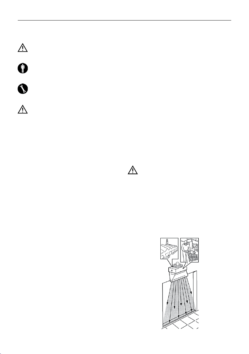
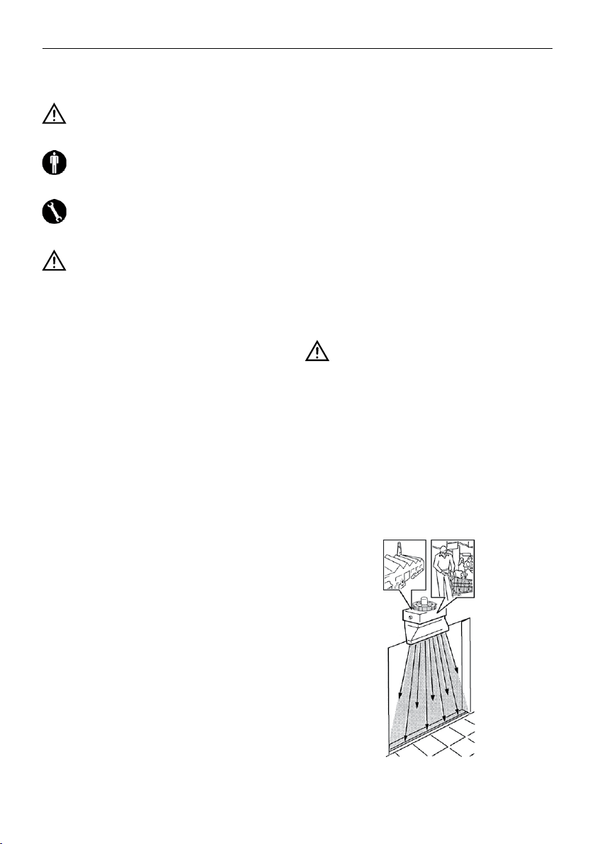
PURPOSE
Before installing the appliance please study
this manual carefully.
The electric Atlas STP door curtain air heaters have
been invented, designed and constructed for the re-
alization of thermodynamical barriers at the doors of
industrial and commercial buildings.
These units are installed over the doors and equipped
with a special diuser. A dense vertical air ow pass-
es through this diuser and generates a screen of
warm air, which prevents the penetration of cold air
from outside.

11
EN
The appliance may not be used:
– for outdoor air treatment
– for installation in moist rooms
– for installation in explosive atmospheres
– for installation in corrosive atmospheres
Make sure that the environment where the appliance
is installed does not contain substances that cause
the corrosion of the aluminium ns.
The unit works with warm water, hot water or with
steam, which is producted by gennerators (boilers).
MAIN COMPONENTS
The casing and the diuser, consist of hot galva-
nized and prepainted steel.
The heat exchange battery consists of aluminium
ns bonded with steel tubes Ø 22 mm or copper
tubes Ø 22 mm headers.
The battery is equipped with threated female head-
ers, on request with ange PN 16.
The electric ventilator is composed of a statical-
ly and dynamically balanced fan with aluminium
blades and is directly xed on the shaft of the asyn-
chronous, three-phase electric motor, closed type. It
is connected with the casing by means of a strong,
basket-like, elastic metal support of anti-vibration
means.
UNIT IDENTIFICATION
Each unit is provided with an identication label,
which informs you on the construction data and the
model type.
The identication label is positioned on the rear side
of the unit.
TRANSPORT
The appliance is transported and delivered in an up-
right position packed in a cardboard box.
The diuser is transported unpacked as a separate
part.
After having unpacked the appliance please make
sure that it does not present any damages and that it
is corresponding to the ordered version.
In case of damages or if the code of the appliance
should not correspond to the ordered model, please
contact the reseller ·and indicate the series as well as
the model number.

12
EN
SAFETY REQUIREMENTS
Before any intervention please make sure that:
1. the unit is not under electric tension
2. the supply valveof the battery water is closed
3. the heat exchange battery cooled down
Please make sure that the earthing has been
correctly performed.
In an easily accesible position near the appliance or
the appliances has to be installed a security switch,
which interrupts the power supply.
For the transport of the air heater plesse use a means,
which can carry its weight (see page with the Techni-
ca Characteristics, Weight Table).
To lift the appliance use the two lugs on the electnc
ventilator. These lugs are exclusively used tor reasing
the appliance. For the suspension plesse use brack-
ets, hooks or other suitable means.
The fans can reach a speed ot 900 RPM.
Please don't introduce any objects or the hands into
the electric ventilator.
If the air heater has to be disassembled, please pro-
tect your hands with working gloves.
Don't approach the electric ventilator with uttering
clothes.
Don't expose the appliance to ammable
gases.
Don't remove the security labels. If they have be-
come unreadable, please ask tor new ones.
The battery has to be protected against frost.
If components have to be substituted, please ask for
original spare parts.
Only qualied and previously trained technical
personnel (and no other person) is authorized to per-
form the maintenance on the appliance.

13
EN
TECHNICAL SPECIFICATIONS
Sound pressure level measured at 5 meters < 70 dB(A)
STP model
Rows Air ow Noise level Peso Capacity Dimensions
n° m3/h dB(A) Kg lmm
6 poles 8 poles 6 poles 8 poles A = B C D E
7
1 4435 3440 69 63 62 4,3
793 696 793 10002 4175 3175 69 63 70 8,2
3 4000 3045 69 63 76 12,3
8
1 6655 4700 69 64 75 5,8
900 803 900 12002 6000 4300 69 64 86 11,1
3 5480 3915 69 64 93 16,6
9
1 9220 6610 70 65 90 7,6
1010 913 1010 14002 8870 6260 70 65 104 14,5
3 8170 5560 70 65 113 21,8
INSTALLATION
We recommend to install the air heaters according to
the dimensions of the door (see table).
STP model Poles Door H Door L
m m
7
6
3,0 ÷ 4,0 1,5
8 3,5 ÷ 4,5 2,0
9 4,5 ÷ 5,5 2,5
7
8
2,5 ÷ 3,0 1,5
8 3,0 ÷ 3,5 1,8
9 3,5 ÷ 4,5 2,0
Please respect a minimum distance for the eventual
maintenance of the fan and the motor.

14
EN
According to the dimensions and the weight of the
appliance and the characteristics of the wall have to
be prepared two steel brackets of the right section
and dimension.
Connect the brackets with metal ropes, chains, rods
or any other suitable means.
Fix the air heater with four M8 screws and washers on
the four suspension hooks.
Lift the appliance with adequate means and hook it
on the suspensions.
Mount the diuser duct by xing it with tour M6
screws, elastic and at washers on the threaded in-
sert of the air heater.
Direct the diusion blades in the way that the air
screen covers the door gap.
WATER CONNECTION
On open system (e.g. when using well water), the wa-
ter used should be cleaned from suspended matter
by means of a lter which should be located in the
inlet. Otherwise there is a risk of erosion due to sus-
pended matter.
You must also ensure that the unit is protected from
dust and other substances that cause an acid or al-
kali reaction when combined with water (aluminum
corrosion).
Supply scheme (warm or hot water).
Don't let trash or impurities penetrate into
the battery, since they could damage the appli-
ance and even arrive to the thermal power plant
where they could ruin pumps, boilers, valves, etc.
To prevent leakage use hamp and tightening paste
for the water charge and discharge.
Equip the tubes with 3-piece joints and exclusion
valves.

15
EN
In the upper part of the circuit has to be introduced
an air vent and in the lower part an opening for the
condensate discharge.
The battery of the air heater has been tested in the
factory at a pressure of 30 bars and is suitable for op-
eration in a hydraulic circuit for pressures up to 16
bars.
Maximum water temperature = max. 170 °C
If the appliance functions with hot water, the joint has
to be substituted by a ange and a counter-ange.
ELECTRICAL CONNECTION
Before performing the electric connections
please make sure that the main switch of the ap-
pliance is in the o position.
Remove the cover from the terminal box of the mo-
tor. Connect the supply cable and the phase wires
with the terminals U1-V1-W1. Please make sure that
the connection plates of the motor are in the right
position in relation to the tension value.
Don’t forget to connect the yellow/green wire with
the earthing (see scheme).
Delta-Star Motors, IP 55.
Connection Δ (High speed)
Connection Y (Low speed)
Upstream of the unit, a disconnection switch must
be provided and shall have a contact separation in all
poles, providing full disconnection under overvolt-
age category III condition.
Size 789
Motor code 3054000 3054000 3054006
Speed
RPM
Δ940 940 900
Y770 770 750
Power
(W)
Δ670 670 1520
Y490 490 1000
Rating
(A)
Δ1,55 1,55 3,40
Y1,00 1,00 2,30

16
EN
Connect the appliance with the power supply and
make sure that the rotation sense of the fan is cor-
rect. If the rotation sense is wrong, switch the appli-
ance o and invert two phase wires on the terminal
board.
Close the cover and tighten the cable with the cable
pressing device.
CLEANING, MAINTENANCE AND
SPARE PARTS
Before performing any cleaning or mainte-
nance please detach the appliance from the pow-
er supply.
Only quailed and previously trained technical
personnel is authorized to intervene on the appli-
ance for maintenance operaitons.
Motor: The electric air heaters mount closed motors
with self-lubricating bail bearings and are mainte-
nance free.
Battery: The heat exchange battery has to be kept
clean to guarantee the technical charactreistics of
the proejct. In periodical intervals you should control
if the nned pack does not show any obstructions in
the air passage. If necessary clean it with a low-pres-
sure jet of compressed air or water. Protect the motor
against damages.
Ventilator: lf noise or vibrations are observed, please
control the tightness of the bolts, which connect
the basket-like support with the housing of the air
heater.
Spare parts: In spare part orders please always indi-
cate the name of the appliance and the description
of the component.
TROUBLESHOOTING
TROUBLE
the motor does not turn or is noisy during operation
REMEDY
– please check if the appliance has been connect-
ed with the power supply
– controlI if all the three phases arrive
– switch the power o, remove the wires tram the
terminal board of the motor and control with an
ohmmeter the continuity of the windings (U1/
U2- V1/V1- W1/W1). If one or more windings are
interrupted, the motor has to be replaced. Please
order an original spare part.

17
FR
SYMBOLOGIE
Attention ! Opérations particulièrement importantes
et/ou dangereuses.
Interventions pouvant être eectuées par l’utilisateur
Interventions à eectuer uniquement par un instal-
lateur ou un technicien autorisé.
Pour les règles fondamentales de sécurité, mises en
garde générales d’installation et plan de l’entretien, voir le
manuel code 4051222 (qui est partie intégrante de l’unité).
UTILISATION ET CONSERVATION DU
MANUEL
Le présent manuel d’instructions s’adresse à l’utilisateur de
l’appareil, au propriétaire et au technicien d’installation,
et doit toujours être disponible pour toute consultation
éventuelle.
Le manuel est destiné à l’utilisateur, au préposé à l’entre-
tien et à l’installateur de l’appareil.
Le manuel d’instructions sert à indiquer l’utilisation de
l’appareil prévue dans les hypothèses de conception et ses
caractéristiques techniques, ainsi qu’à fournir des indica-
tions pour son utilisation correcte, le nettoyage, le réglage
et le fonctionnement ; il fournit également d’importantes
indications concernant l’entretien, les éventuels risques ré-
siduels et, de manière générale, les opérations dont l’exé-
cution exige une attention particulière.
Le présent manuel doit être considéré comme une partie
intégrante de l’appareil et doit être conservé en vue de
futures consultations jusqu’à son démantèlement nal.
Le mode d’emploi doit toujours être disponible pour la
consultation, et conservé dans un lieu protégé et sec.
En cas de perte ou de détérioration, l’utilisateur peut de-
mander un nouveau manuel au fabricant ou à son reven-
deur, en indiquant le numéro du modèle et le numéro de
série de l’appareil, indiqué sur sa plaque d’identication.
Le présent manuel reète l’état de la technique au moment
de sa rédaction; le fabricant se réserve le droit de mettre à
jour la production et les manuels suivants sans obligation
de mettre également à jour les versions précédentes.
Le constructeur se décharge d’éventuelles responsabilités
en cas de:
– utilisation impropre on incorrecte de l’appareil;
– utilisation non conforme aux spécications fournies
dans les présente publication;
– grave carence dans l’entretien prévu et conseillé;
– modications de l’appareil ou toute autre interven-
tion non autorisée;
– utilisation de pièces de rechange non originales ou
non spéciques au modèle;
– non-respect, total ou même partiel, des instructions;
– évènements exceptionnels.
BUT
Avant l’installation de l’aerotherme lire la present
notice.
Les aérothermes à lame d'air Atlas STP ont été conçus,
projetés et construits pour réaliser des barrières ther-
modynamiques sur les portes des édices industriels et
commerciaux.
Ces appareils sont installés sur les portes et munis d’un
conduit fuselé spécial pour le ux vertical d’air chaud qui
forme en épais rideau et empêche l’entrée de l’air froid de
dehors.
L’appareil ne peut pas:
– pour le traitement de l’air en plein air
– être installé dans des locaux humides
– être installé dans des atmosphères explosives
– être installé dans des atmosphères corrosives

18
FR
Vérier que la pièce dans laquelle l’appareil est installé ne
contient pas de substances pouvant en- gendrer la corro-
sion des ailettes en aluminium.
Les unités sont alimentés par eau chaude, eau surchauée
ou vapeur produit de générateurs (chaudières).
COMPOSANTS PRINCIPAUX
Le bati et le conduit sont en tôle d’acier galvanisée à
chaud et vernie.
La batterie d'echange thermique de l’appareil est com-
posée de tubes en acier Ø 22 mm ou de tubes en cuivre Ø
22 mm et d’ailettes en aluminium.
La batterie est muni de connexions femelles letées ou de
ange PN 16.
L’electroventilateur est composé d’une hélice avec des
pales en aluminium, statiquement et dynamiquement, ba-
lancée et calée sur l’arbre du moteur électrique triphasé,
version fermée, et xé au bâti avec un support robuste en
métal avec l’interposition de dispositifs antivibrants.
IDENTIFICATION DE L'APPAREIL
Sur chaque appareil est appliquée une étiquette qui in-
dique le données de construction et le modèle.
L’étiquette est positionnée derrière l’appareil.
TRANSPORT
L'appareil est transporté et remis emballé soutenu dans un
carton.
Le conduit (diuseur à lame d'air) est transporté séparé-
ment sans emballage.
Après le déballage il faut contrôler immédiatement qu'il
n'y ait pas de dommages et que l'appareil corespond à
votre commande.
En cas de dommages ou d'étiquette qui ne correspond pas
à ce qui a été commandé il faut s'adresser au propre reven-
deur en citant la série e le modèle.
PRESCRIPTIONS DE SÉCURITÉ
Avant d'eectuer n'importe quelle intervention, il faut s'as-
surer que:
1. l'aérotherme ne soit pas sous tension

19
FR
2. la vanne d'alimentation de l'eau de la batterie soit
fermée
3. la batterie d'échange se soit refroidie
Contrôler qu'il y a une correcte mise à la terre.
Dans une position facilement accesible près de l'appareil
ou des appareils il faut installer un interrupteur de sécurité
qui coupe la tension a l'appareil.
Pour transporter l'appareil au lieu d'emploi il taut utiliser
un moyen de soulèvement indiqué pour le poids de l'appa-
reil (voir Données Techniques, Tableau des Poids).
Pour soulever l'appareil il faut utiliser les deux anneaux sur
l'électroventilateur. Ces anneaux s'emploient seulement
pour le soulèvement de l'appareil. Pour la suspension
il faut utiliser des consoles, des anses ou chaque autre
moyen indiqué.
Les hélices peuvent réjoindre une vitesse de 900 TPM.
Il ne faut pas introduire des objets ou les mains dans
l'électroventilateur.
Pour le démontage de l'aérotherme il faut protéger les
mains avec des gants de travail.
Ne pas s'approcher de l'appareil avec des vêtements
ottants.
Il ne faut pas exposer l'appareil aux gaz
inammable.
Ne pas détacher les étiquettes de sécurité. Si les étiquettes
sont devenues illisibles, il faut demander le remplacement.
Protéger la batterie contre le froid.
Pour le remplacement de parts il faut toujours demander
des pièces de réchange originales.
Seulement techniciens (et personne d’autre) précé-
démment formés, qualiés et autorisés peuvent accéder à
l’appareil pour eectuer l’entretien.

20
FR
CARACTÉRISTIQUES TECHNIQUES
Niveau de pression sonore mesuré à 5 mètres < 70 dB(A)
Modèle STP
Rangs Débit d’air Bruit Peso Capacité Dimensions
n° m3/h dB(A) Kg lmm
6 pôles 8 pôles 6 pôles 8 pôles A = B C D E
7
1 4435 3440 69 63 62 4,3
793 696 793 10002 4175 3175 69 63 70 8,2
3 4000 3045 69 63 76 12,3
8
1 6655 4700 69 64 75 5,8
900 803 900 12002 6000 4300 69 64 86 11,1
3 5480 3915 69 64 93 16,6
9
1 9220 6610 70 65 90 7,6
1010 913 1010 14002 8870 6260 70 65 104 14,5
3 8170 5560 70 65 113 21,8
INSTALLATION
Selon les dimensions de la porte (voir le tableau) il faut
chosir les aérothermes appropriés.
Modèle STP Pôles Porte H Porte L
m m
7
6
3,0 ÷ 4,0 1,5
8 3,5 ÷ 4,5 2,0
9 4,5 ÷ 5,5 2,5
7
8
2,5 ÷ 3,0 1,5
8 3,0 ÷ 3,5 1,8
9 3,5 ÷ 4,5 2,0
Respecter une distance minimum pour l’entretien éventuel
du moteur et de l’hélice.
Table of contents
Languages:
Other Sabiana Heater manuals