SAC MAXI-MIXER 4600 TRAILER User manual

877 1st Ave. N.W. | Sioux Center, IA 51250 | Toll Free: 1.866.722.1488 | siouxautomation.com
OPERATION
REPLACEMENT PARTS
READ complete manual CAREFULLY
BEFORE attempting operation.
OPERATORS MANUAL
4600 TRAILER
MON600146 Rev V 8/04/21
MAXI-MIXER

Page # 2
877 1st Ave. N.W. | Sioux Center, IA 51250 | Toll Free: 1.866.722.1488 | siouxautomation.com
OPERATION
REPLACEMENT PARTS
READ complete manual CAREFULLY
BEFORE attempting operation.
REV DATE BILL OF MATERIALS DESCRIPTION
F7/25/13 MON900505, MON900506
MON900507, MON900508
MON900509, MON900510
MON900511, MON900512
MON900514, MON900517
MON900837, MON900845
MON900847,MON900848
MON900970,MON800563
MON700906
UPDATE AUGER DISCHARGES TO REFLECT
CHANGES IN HYDRAULIC CYLINDERS
ADDED DRIVELINE BREAKDOWN
ADDED COUNTER CLOCK-WISE TOP LEFT
HAND AUGER
G 01/07/14 UPDATE ALL GRAPHICS AND BOM’S
H 07/09/14 MON900990 UPDATE ALL GRAPHICS AND BOM’S &
ADD MON900990
J 11/5/14 MON900484 ADD MON901004 & MON901004-1 TO SALES
OPTIONS
K 1/8/15 UPDATE ALL GRAGHICS AND BOM’S
ADDED SLAT DISCHARGE BASE ASSY’S
ADDED SCALE KITS
ADDED HYDRAULIC KITS
L 4/5/17 REVIEWED ALL DRAWINGS AND BOM’S AND
UPDATED AS NEEDED.
P 10/15/19 MON701718 REPLACE TRAILER MON700841 WITH
MON701718
Q 11/7/19 MON900484 CHG QTY OF BLT12X214NC QTY 8 WAS 16
CHG QTY OF BLT12X2NC QTY 10 WAS 2
R 02/07/20 MON900436 ADD MON104592 DISK,11,3.63,.38,STL QTY2
CHG MON102494 DISK,7.5,3.63,.38,STL QTY
2 WAS QTY 4
S 03/10/20 DECAL LOCATION ADD DECAL DEC788 QTY 2
T 12/21/20 DECAL LOCATION ADD DECAL DEC795 QTY 2
U 6/28/21 SPEC SHEET UPDATED SPECIFICATION SHEET
V 8/4/21 BASE ASSEMBLY WITH CAM LOCK
DOORS ADD BASE ASSY MON901114 AND DOOR KITS
MON901139 - MON901140

Page # 3
877 1st Ave. N.W. | Sioux Center, IA 51250 | Toll Free: 1.866.722.1488 | siouxautomation.com
OPERATION
REPLACEMENT PARTS
READ complete manual CAREFULLY
BEFORE attempting operation.
Table of Contents
General Information.....................................................................................................................................................................................................3
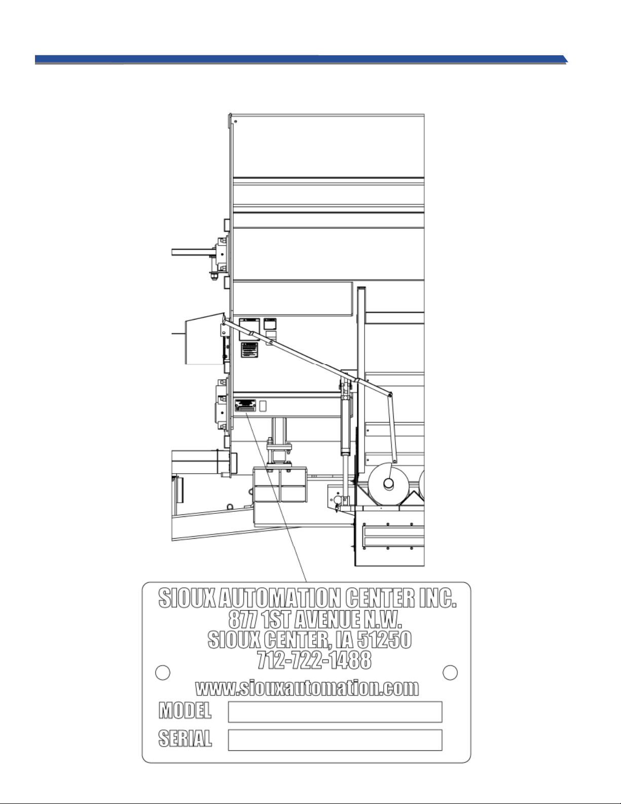
Model and Serial Number Identication..............................................................................................................................................................4
Safety , Signal Words....................................................................................................................................................................................................6
Equipment Safety Guidelines...................................................................................................................................................................................7
Lighting and Marking..................................................................................................................................................................................................7
Safety Sign Care.............................................................................................................................................................................................................7
Tire Safety ........................................................................................................................................................................................................................8
Before Operation...........................................................................................................................................................................................................8
During Operation.......................................................................................................................................................................................................9-10
Following Operation...................................................................................................................................................................................................10
Highway and Transport Operations.................................................................................................................................................................. 10-11
Performing Maintenance ..........................................................................................................................................................................................11
Bolt Torque .....................................................................................................................................................................................................................12
PTO Horsepower Requirements .............................................................................................................................................................................13
Drawbar Attaching System.......................................................................................................................................................................................13
Hydraulic System..........................................................................................................................................................................................................13
Mixer Setup....................................................................................................................................................................................................................13
Mixer Operation........................................................................................................................................................................................................ 14-15
Maintenance/Inspections and Adjustments......................................................................................................................................................16
Lubrication Schedule..................................................................................................................................................................................................17
Planetary Notes ............................................................................................................................................................................................................18
Decal Locations ............................................................................................................................................................................................................19
Base Assemblies and Door Kits........................................................................................................................................................................... 20-28
Final Assembly .......................................................................................................................................................................................................... 30-36
Subframe Assembly ....................................................................................................................................................................................................32
Hub Breakdown ...........................................................................................................................................................................................................33
Lighting Assembly................................................................................................................................................................................................... 34-35
Auger Assemblies .................................................................................................................................................................................................... 36-37
Auger Roughage Kit ...................................................................................................................................................................................................38
Discharge Assemblies............................................................................................................................................................................................. 39-51
Discharge Hydraulic Assemblies ........................................................................................................................................................................ 52-57
Switchbox Assembly...................................................................................................................................................................................................58
Driveline Breakdown .............................................................................................................................................................................................. 59-60
Extension Kit .................................................................................................................................................................................................................61
Scale Kit Assemblies ...................................................................................................................................................................................................62
General Specications................................................................................................................................................................................................63
Warranty...................................................................................................................................................................................................................... 64-65
Never overload wagon. Follow rating of gear or rating of tires, whichever is less.
Ensure that anybody present is clear before applying power to any machinery used in conjunc-
tion with wagon box or when moving box.
Never allow anyone in, near, or on mixing chamber during mixing, transporting, or unloading
of feed.
Do not exceed 20 miles per hour when towing wagon.
GENERAL INFORMATION
1. Unless otherwise specied, high-strength (grade5) (3 radi-
al-line head markings) hex head bolts are used throughout
assembly of this piece of equipment.
2. Whenever terms“LEFT”and“RIGHT”areusedinthismanual
it means from a position behind the wagon box and facing
forward.
3. When placing a parts order, refer to this manual for
proper part numbers and place order by PART NO. and
DESCRIPTION.
4. Read assembly instructions carefully. Study
assembly procedures and all illustrations before you
begin assembly. Note which parts are used in each
step. This unit must be assembled in proper sequence
or complications will result.
WARNING: TO AVOID PERSONAL INJURY OR DEATH, OBSERVE FOLLOWING INSTRUCTIONS:
Thank you for purchasing a Sioux Automation Maxi-Mixer 4000 series mixer. We feel you have made a
wise choice and hope you are completely satisfied with your new piece of equipment. Your new 4000
series Maxi-Mixer is a durable, ecient, and easy to use unit. Proper care and use will result in many years of service.

Page # 4
877 1st Ave. N.W. | Sioux Center, IA 51250 | Toll Free: 1.866.722.1488 | siouxautomation.com
OPERATION
REPLACEMENT PARTS
READ complete manual CAREFULLY
BEFORE attempting operation.
Your model and serial numbers can be located on the front left hand side of the mixer. Please copy this information and write them
down inside of this manual. This will allow easy reference if the ordering of parts should become necessary.
MODEL AND SERIAL NUMBER IDENTIFICATION

877 1st Ave. N.W. | Sioux Center, IA 51250 | Toll Free: 1.866.722.1488 | siouxautomation.com
OPERATION
REPLACEMENT PARTS
READ complete manual CAREFULLY
BEFORE attempting operation.
_____________________________________________________________________________________________
_____________________________________________________________________________________________
_____________________________________________________________________________________________
_____________________________________________________________________________________________
_____________________________________________________________________________________________
_____________________________________________________________________________________________
_____________________________________________________________________________________________
_____________________________________________________________________________________________
_____________________________________________________________________________________________
_____________________________________________________________________________________________
_____________________________________________________________________________________________
_____________________________________________________________________________________________
_____________________________________________________________________________________________
_____________________________________________________________________________________________
_____________________________________________________________________________________________
_____________________________________________________________________________________________
_____________________________________________________________________________________________
_____________________________________________________________________________________________
_____________________________________________________________________________________________
_____________________________________________________________________________________________
_____________________________________________________________________________________________
_____________________________________________________________________________________________
_____________________________________________________________________________________________
_____________________________________________________________________________________________
_____________________________________________________________________________________________
_____________________________________________________________________________________________
_____________________________________________________________________________________________
_____________________________________________________________________________________________
_____________________________________________________________________________________________
_____________________________________________________________________________________________
_____________________________________________________________________________________________
_____________________________________________________________________________________________
_____________________________________________________________________________________________
_____________________________________________________________________________________________
_____________________________________________________________________________________________
_____________________________________________________________________________________________
NOTES
Page # 5

Page # 6
877 1st Ave. N.W. | Sioux Center, IA 51250 | Toll Free: 1.866.722.1488 | siouxautomation.com
OPERATION
REPLACEMENT PARTS
READ complete manual CAREFULLY
BEFORE attempting operation.
TAKE NOTE! THIS SAFETY ALERT SYMBOL FOUND THROUGHOUT THIS
MANUAL IS USED TO CALL YOUR ATTENTION TO INSTRUCTIONS INVOLVING
YOUR PERSONAL SAFETY AND SAFETY OF OTHERS. FAILURE TO FOLLOW THESE
INSTRUCTIONS CAN RESULT IN INJURY OR DEATH!
THIS SYMBOL MEANS
ATTENTION
BECOME ALERT
YOUR SAFETY IS INVOLVED!
SIGNAL WORDS
Note: use of following signal words DANGER, WARNING,
and CAUTION with safety messages. Appropriate signal
word for each has been selected using following guidelines:
DANGER:
Indicates an imminently hazardous situation that, if not
avoided, will result in serious injury or death. This signal
word is to be limited to most extreme situations typically
for machine components which, for functional purposes,
cannot be guarded.
WARNING:
Indicates a potentially hazardous situation that, if not
avoided, could result in serious injury or death, and includes
hazards that are exposed when guards are removed. It may
also be used to alert against unsafe practices.
CAUTION:
Indicates a potentially hazardous situation that, if not
avoided, may result in minor or moderate injury. It may
also be used to alert against unsafe practices.
If you have questions not answered in this manual , require additional copies, or if your manual is damaged, please contact
your dealer or Sioux Automation Center Inc., 877 1st Ave NW, Sioux Center, IA 51250, ph: (712) 722-1488 or
Toll Free: 1-866-722-1488, Fax: (712) 722-1487 http://www.siouxautomation.com
SAFETY: YOU CAN LIVE WITH IT!

Page # 7
877 1st Ave. N.W. | Sioux Center, IA 51250 | Toll Free: 1.866.722.1488 | siouxautomation.com
OPERATION
REPLACEMENT PARTS
READ complete manual CAREFULLY
BEFORE attempting operation.
SAFETY...YOU CAN LIVE WITH IT
EQUIPMENT SAFETY GUIDELINES
Every year many accidents occur which could have been avoided by a few seconds of thought and a more careful
approach to handling equipment.You, the operator, can avoid many accidents by observing the following precautions
in this section. To avoid personal injury, study the following precautions and insist those working with you, and you
yourself, follow them.
In order to provide a better view, certain illustrations in this manual may show an assembly with a safety shield
removed. However, equipment should never be operated in this condition. Keep all shields in place. If shield removal
becomes necessary for repairs, replace shield prior to use.
Replace any CAUTION, WARNING, DANGER or instruction safety decal that is not readable or is missing. Location of
such decals is indicated in this manual. The part numbers for the decals are located in the lower right hand corner of
the decal, and listed in this manual on the following pages.
Do not attempt to operate this equipment under the inuence of alcohol or drugs.
Review safety instructions with all users annually.
Operator should be a responsible adult. DO NOT ALLOW PERSONSTO OPERATE OR ASSEMBLETHIS UNIT UNTIL THEY
HAVE READTHIS MANUAL AND HAVE DEVELOPED ATHOROUGH UNDERSTANDING OF THE SAFETY PRECAUTIONS
AND PROPER OPERATIONAL PROCEDURES.
Do not paint over, remove, or deface any safety signs or warning decals on your equipment. Observe all safety signs
and practice the instructions on them.
Never exceed limits of a piece of machinery. If its ability to do a job, or to do so safely is in question DON’T TRY IT.
LIGHTING AND MARKING
It is the responsibility of customer to know lighting and marking requirements of the local highway authorities and to
install and maintain the equipment to provide compliance with the regulations. Add extra lights when transporting
at night or during periods of limited visibility. Lighting kits are available from your dealer or from manufacturer.
SAFETY SIGN CARE
• Keepsafetysignscleanandlegibleatalltimes.
• Replacesafetysignsthataremissingorhavebecomeillegible.
• Replacedpartsthatdisplayedsafetysignsshouldalsodisplaycurrentsafetysign.
• Safetysignsareavailablefromyourdistributor,dealerpartsdepartment,orthefactory.
How to install safety signs:
• Besurethatinstallationareaiscleananddry.
• Decideonexactpositionbeforeyouremovebackingpaper.
• Removesmallestportionofsplitbackingpaper.
• Aligndecaloverspeciedareaandcarefullypresssmallportionwithexposedstickybackinginplace.
• Slowlypeelbackremainingpaperandcarefullysmoothremainingportionofdecalintoplace.
• Smallairpocketscanbepiercedwithapinandsmoothedoutusingpieceofdecalbackingpaper.
SAFETY

Page # 8
877 1st Ave. N.W. | Sioux Center, IA 51250 | Toll Free: 1.866.722.1488 | siouxautomation.com
OPERATION
REPLACEMENT PARTS
READ complete manual CAREFULLY
BEFORE attempting operation.
TIRE SAFETY
• Failuretofollowproperprocedureswhenmountingatireonarimcanproduceanexplosionwhichmay
result in a serious injury or death.
• Donotattempttomountatireunlessyouhaveproperequipmentandexperiencetodothejob.
• Inatingorservicingtirescanbedangerous.Wheneverpossible,trainedpersonnelshouldbecalledto
service and/or mount tires.
• Alwaysorderandinstalltiresandwheelswithappropriatetypeandloadcapacitytomeetorexceed
anticipated weight to be placed on the equipment.
REMEMBER
Your best assurance against accidents is a careful and responsible operator. If there is any portion of this
manual or function you do not understand, contact your local authorized dealer or manufacturer.
BEFORE OPERATION:
• Carefullystudyandunderstandthismanual.
• Donotwearloose-ttingclothingwhichmaycatchinmovingparts.
• Alwayswearprotectiveclothingandsubstantialshoes.
• Itisrecommendedthatsuitablehearingandeyeprotectionbeworn.
• Operatormaycomeincontactwithcertainmaterialswhichmayrequirespecicsafetyequipment
relative to handling of such materials.
• Keepwheelandlugnutstightenedtospeciedtorque.
• Assurethatagriculturalimplmenttiresareinatedevenly.
• Giveunitavisualinspectionforanyloosebolts,wornpartsorcrackedwelds,andmakenecessary
repairs. Follow the maintenance safety instructions included in this manual.
• Besuretherearenotoolslyingonorinequipment.
• Donotuseunituntilyouaresurethatareaisclear,especiallyaroundchildrenandanimals.
• Don’thurrythelearningprocessortaketheunitforgranted.Easeintoitandbecomefamiliar
with your new equipment.
• Practiceoperationofyourequipmentanditsattachments.Completelyfamiliarizeyourselfandother
operators with its operation before using.
• UseatractorequippedwithRollOverProtectionSystem(ROPS)andfastenyourseatbeltpriorto
starting the engine.
• ManufacturerdoesnotrecommendusageofatractorwiththeROPSremoved.
• Makesurethatbrakesareevenlyadjusted.
• Movetractorwheelstowidestrecommendedsettingstoincreasestability.
• Donotallowanyonetostandbetweentongueorhitchandtowingvehiclewhenbackinguptoequipment.
• NEVERloadmixerwithoutrstattachingatractorofatleast2/3thegrosstrailerweight.
SAFETY

Page # 9
877 1st Ave. N.W. | Sioux Center, IA 51250 | Toll Free: 1.866.722.1488 | siouxautomation.com
OPERATION
REPLACEMENT PARTS
READ complete manual CAREFULLY
BEFORE attempting operation.
DURING OPERATION
• Beawareofbystanders,PARTICULARLYCHILDREN!Alwayslookaroundtomakesurethatitissafeto
start the engine or to move the unit. This is particularly important with higher noise levels and quiet cabs, as you
may not hear people shouting.
• NOPASSENGERSALLOWED-Donotallowanyonetorideonorinsidethemixeratanytime!
• Keephandsandclothingclearofmovingparts.
• Donotclean,lubricate,oradjustyourequipmentwhileitismoving.
• Whenhaltingoperation,evenperiodically,setparkingbrakes,disengagePTO,shuto
engine, and remove ignition key.
• Beespeciallyobservantoftheoperatingareaandterrain.Watchforholes,rocks,orotherhiddenhazards.
Always inspect area prior to operation.
-DONOToperatenearedgeofdrop-osorbanks.
- DO NOT operate on steep slopes as overturn may result.
- Operate up and down (not across) intermediate slopes. Avoid sudden starts and stops.
• Pickthemostlevelpossibleroutewhentransportingacrosselds.Avoidedgesofditches,gullies,andsteep
hillsides.
• Beextracarefulwhenworkingoninclines.
• Maneuvertractorortowingvehicleatsafespeeds.
• Avoidoverheadwiresorotherobstacles.Contactwithoverheadlinescouldcauseseriousinjuryordeath.
• Avoidloosegravel,rocks,andholes;theycanbedangerousforequipmentoperationormovement.
• Allowforunitlengthwhenmakingturns.
• Donotwalkorworkunderraisedcomponentsorattachmentsunlesssecurelypositionedandblocked.
• Keepallbystanders,pets,andlivestockclearofworkarea.
• Operatetowingvehiclefromoperatorsseatonly.
• Neverstandalongsideofunitwithenginerunningorattempttostartengineand/oroperatemachinewhile
standing alongside of unit.
• Neverleaverunningequipmentunattended.
• Asaprecaution,alwaysrecheckhardwareonequipmentfollowingevery100hoursofoperation.Correctall
problems. Follow maintenance safety procedures.
• Neverhandfeedmaterialsintomixerwhileitisrunning.Rotatingaugersinsidemixermaynotbevisiblefrom
the loading point, and may cut or grab hands, clothing, or material being loaded, causing severe injury.
Always stop tractor engine before hand loading materials.
• Donotallowoperationofthisunitbyinexperiencedorunqualiedpeople.Keepallunqualifedpeopleaway
from the mixer during operation. Operators of this unit must be alert and use good judgement at all
times. Operator should not climb on ladder or any part of the mixer when loading, mixing, or unloading material.
SAFETY

Page # 10
877 1st Ave. N.W. | Sioux Center, IA 51250 | Toll Free: 1.866.722.1488 | siouxautomation.com
OPERATION
REPLACEMENT PARTS
READ complete manual CAREFULLY
BEFORE attempting operation.
• Besuretheinsideofthemixerisclearofanyobstructionbeforeoperating.
• Usecautionwhenworkingaroundthedischargearea.Stayclearofpowerchute&slidetray.Theseare
controlled from the cab and could operate without warning, creating pinch points which could cause severe
injury or death. Always stop tractor engine and remove PTO driveline & hydraulic hoses before working
near the discharge area.
• Neverattempttoreleasejammedmaterialsorcleanmaterialsfromanyareaofthemixerordischarge
chute without stopping engine and removing driveline rst. Moving parts can be hidden by materials, and
stopped parts can start unexpectedly, causing severe injury. Always stop tractor engine and remove the PTO
driveline so that the mixer before attempting to remove jammed material or to clean.
• Neverputarmsorfeetinsideunit,powerchute,orneardischargedooropening,norclimbonorinthemixer
while it is running. NEVER allow anyone to position themselves over or near the top of the mixer while it is
running. Rotating augers and sprockets can grab clothing or create pinch points which can cause severe
injury or death to the operator or bystanders. Always stop tractor engine and remove the PTO driveline so
that the mixer cannot be accidentally turned on while inspecting, servicing, repairing, or cleaning.
• Followingoperation,orwhenunhitching,stoptractorortowingvehicle,setbrakes,shutoengineand
remove the ignition key.
• Storeunitinanareaawayfromhumanactivity.
• Donotparkequipmentwhereitwillbeexposedtolivestockforlongperiodsoftime.Damageand
livestock injury could result.
• Donotpermitchildrentoplayonoraroundstoredunit.
• Makesureallparkedmachinesareonahard,levelsurfaceandengageallsafetydevices.
• Wheelchocksmaybeneededtopreventunitfromrolling.
FOLLOWING OPERATION
HIGHWAY AND TRANSPORT OPERATIONS
• SAFETY CHAINS: If equipment is going to be transported on a public highway, always follow state and
local regulations regarding safety chains and auxiliary lighting. Be sure to check with local law enforcement
agencies for your own particular regulations. If required, safety chains should be obtaines and installed
Only safety chains (not elastic or nylon/plastic tow straps) should be used to retain connection between
towing and towed machines in the event of separation of primary attaching system. Use a high strength,
appropriately sized hitch pin with a mechanical retainer and attach safety chains. Criss cross chains under
tongue and secure to draw bar cage, mounting loops, or bumper frame.
• Adoptsafedrivingpractices:
- Keep brake pedals latched together at all times. NEVER USE INDEPENDENT BRAKING WITH
MACHINE IN TOW, LOSS OF CONTROL AND/OR UPSET OF UNIT CAN RESULT.
- Always drive at a safe speed relative to local conditions, ensure that your speed is low enough for an
emergency stop. Keep speed to a minimum.
- Reduce speed prior to turns to avoid risk of overturning.
- Always keep tractor or towing vehicle in gear to provide engine braking when going downhill.
Do not coast.
- Do not drink and drive!
SAFETY

Page # 11
877 1st Ave. N.W. | Sioux Center, IA 51250 | Toll Free: 1.866.722.1488 | siouxautomation.com
OPERATION
REPLACEMENT PARTS
READ complete manual CAREFULLY
BEFORE attempting operation.
• Comply with state and local laws governing highway safety and movement of farm machinery on public roads.
• Use approved accessory lighting, ags and necessary warning devices to protect operators of other vehicles on
highway during transport. Various safety lights and devices are available from your dealer.
• Use of ashing amber lights is acceptable in most localities. However, some localities prohibit their use. Local laws
should be checked for all highway lighting and marking requirements.
• When driving tractor and equipment on road under 20 m.p.h. (40 kph) at night or during day, use ashing amber
warning lights and a slow moving vehicle (SMV) identication emblem.
• Plan your route to avoid heavy trac.
• Be a safe and courteous driver. Always yield to oncoming trac in all situations, including narrow bridges, inter-
sections, etc.
• Be observant of bridge load ratings. Do not cross bridges rated lower than gross weight at which you are operating.
• Watch for obstructions overhead and side to side while transporting.
• Always operate equipment in a position to provide maximum visibility. Make allowances for increased length and
weight of equipment when making turns, stopping unit, etc.
SAFETY
HIGHWAY AND TRANSPORT OPERATIONS
• Good maintenance is your responsibility. Poor maintenance is an invitation for trouble.
• Make sure there is plenty of ventilation. Never operate engine in a closed building. Exhaust fumes may cause
asphyxiation.
• Beforeworkingonthismachine,stoptowingvehicle,setbrakes,shutoengineandremove ignition key.
• Always use safety support and block wheels. Never use a jack to support machine.
• Always use proper tools or equipment for job at hand.
• Use extreme caution when making adjustments.
• Follow torque chart in this manual when tightening bolts and nuts.
• Never use your hands to locate a hydraulic leak on attachments. Use a small piece of cardboard or wood. Hydraulic
uid escaping under pressure can penetrate skin.
• Openings in skin and minor cuts are susceptible to infection from hydraulic uid. Without immediate medical
treatment, serious infection and reactions can occur.
• Whendisconnectinghydrauliclines,shutohydraulicsupplyandrelieveallhydraulicpressure.
• Replace all shields and guards after servicing and before moving equipment.
• After servicing, be sure all tools, parts, and service equipment are removed.
• Do not allow grease or oil to build up on any step or platform.
• When replacing bolts, refer to owner’s manual.
• Refer to bolt torque chart for head identication marking.
• Where replacement parts are necessary for periodic maintenance and servicing, genuine factory replacement parts
must be used to restore your equipment to original specications. Manufacturer will not claim responsibility for
use of unapproved parts or accessories and other damages as a result of their use.
• If equipment has been altered in any way from original design, manufacturer does not accept any liability for injury
or warranty.
• A re extinguisher and rst aid kit should be kept readily accessible while performing maintenance on this equipment.
PERFORMING MAINTENANCE

Page # 12
877 1st Ave. N.W. | Sioux Center, IA 51250 | Toll Free: 1.866.722.1488 | siouxautomation.com
OPERATION
REPLACEMENT PARTS
READ complete manual CAREFULLY
BEFORE attempting operation.
TORQUE DATA FOR STANDARD NUTS, BOLTS, AND CAP SCREWS.
Tighten all bolts to torques specied in chart unless otherwise noted. Check tightness of bolts periodically, using bolt
chart as guide. Replace hardware with same grade bolt.
NOTE: Unless otherwise specied, high-strength Grade 5 hex bolts are used throughout assembly of equipment.
Bolt Torque for Standard bolts *
GRADE 2 GRADE 5 GRADE 8
“A” lb-ft (N.m) lb-ft (N.m) lb-ft (N.m)
1/4” 6 (8) 9 (12) 12 (16)
5/16” 10 (13) 18 (25) 25 (35)
3/8” 20 (27) 30 (40) 45 (60)
7/16” 30 (40) 50 (70) 80 (110)
1/2” 45 (60) 75 (100) 115 (155)
9/16” 70 (95) 115 (155) 165 (220)
5/8” 95 (130) 150 (200) 225 (300)
3/4” 165 (225) 290 (390) 400 (540)
7/8” 170 (230) 420 (570) 650 (880)
1” 225 (300) 630 (850) 970 (1310)
Torque gures indicated are valid for non-greased
or non-oiled threads and heads unless otherwise
specfied. Therefore, do not grease or oil bolts
or capscrews unless otherwise specied in this
manual. When using locking
elements, increase torque values
by 5%.
* GRADE or CLASS value for bolts and capscrews
are identied by their head markings.
Torque Specications
CLASS 8.8 CLASS 9.8 CLASS 10.9
“A” lb-ft (N.m) lb-ft (N.m) lb-ft (N.m)
6 9 (13) 10 (14) 13 (17)
7 15 (21) 18 (24) 21 (29)
8 23 (31) 25 (34) 31 (42)
10 45 (61) 50 (68) 61 (83)
12 78 (106) 88 (118) 106 (144)
14 125 (169) 140 (189) 170 (230)
16 194 (263) 216 (293) 263 (357)
18 268 (363) -- -- 364 (493)
20 378 (513) -- -- 515 (689)
22 516 (699) -- -- 702 (952)
24 654 (886) -- -- 890 (1206)
Bolt Torque for Metric bolts *
GRADE-2 GRADE-5 GRADE-8
CLASS 8.8 CLASS 9.8 CLASS 10.9
8.8 10.9
9.8
BOLT TORQUE

Page # 13
877 1st Ave. N.W. | Sioux Center, IA 51250 | Toll Free: 1.866.722.1488 | siouxautomation.com
OPERATION
REPLACEMENT PARTS
READ complete manual CAREFULLY
BEFORE attempting operation.
PTO HORSEPOWER REQUIREMENTS
• PTO horsepower requirements are based on most normal dairy or beef rations. Horsepower requirements may vary
depending on the ration or material to be mixed.
• Refer to tractor weight requirements for these recommendations and transporting safety precautions for additional
tractor and towing requirements.
DRAWBAR ATTACHING SYSTEM
• Adjust tractor drawbar and/or the mixer clevis hitch so that the mixer is approximtely level. The top of the drawbar
should be 8”-12” below the tractor PTO shaft. Adjust the drawbar horizontally so that the hitch pin hole is 14”-16”
behind the tractor PTO and the drawbar is centered and locked into place.
• A hitch pin with a minumum of 1”diameter with a retainer pin is recommended.
HYDRAULIC SYSTEM
• Dual hydraulic outlets are required for operating the door and either the slide tray or the powerchute. If your tractor
has only a single set of ports, then either the 3 bank valve option or one of the 2 hose with manual selector valve
options should be ordered. On units with the power chute option, the chute hoses may be dicult to connect due
tothechuteweightontheliftcylinder.Liftweightochutecylindertoconnecthoses.Tractorhydraulicsystem
requirements are 6 GPM @ 1500 PSI when a slide tray is used, 15 GPM @2000 PSI when a 3-auger power chute is used.
MIXER SETUP
MIXER RUNIN
• To adjust the height of the power chute, change the length of the link chains on the sides of the chute. For best
performance,theunloadingheightshouldbesetatthelowestheightpossible.Thedischargetip-oonthepower
chute should be adjusted for correct magnet and discharge angle. Remove or loosen the upper bolts, pivot the tip
otothedesiredanglesandreinstallorretightenallbolts.
POWER CHUTE ADJUSTMENT OPTIONAL
To avoid personal injury: The hopper oor may be slippery and the auger can spin unexpectedly when stepped on.
Use caution when stepping or standing inside the unit, place a protective cover over the auger knives when work
inside the box is required.
MIXER SETUP
A. Before Starting:
•Besureallshieldsareproperlyinplace.
•Cycletheunloadingdoorandconveyorseveraltimestofullychargethehydraulicsystemwithoil.
•Besurethattheaugersandreelcanturnfreely.
•Checkfordebrisand/oranyotheritemsthatcouldblockoraectmachineoperation.
•Besurethatdrainplugsareinstalledandthedoorisclosed.
B. Test run the mixer.
•Makesuremixerisempty,thenstartthemixer.
•RunforatleastveminutesatrecommendedRPM.
•Raiseandlowerthedoorandoperatetheconveyor/slidetrayseveraltimes.
•Disengagethemixerandturnothetractorengineandremovetheignitionkey.
•Checkthemixerdrivecomponentstobesuretheyarenotabnormallyhot.
C. After operating for ½ hour:
•Checkthatallboltsandfastenersarealltightenedproperly.(SeeTorqueSpec.)
•Checkthatallwheelnutsaretight.
•Checktheaugersandreel.Removeallstring,twine,orotherentangledmaterial.
•Checkthatnohosesarepinched,rubbing,orbeingcrimped.Re-alignasrequired.
•Checkforoilleaks.Stopleaksbeforecontinuing.
•Lubricateallgreasettings.
D. After operating for 5 hours and 10 hours:
•Re-torqueallwheelnuts,fasteners,andhardware.
•Checktheaugersandreel.Removeallstring,twine,orotherentangledmaterial.
•ProceedwithnormalservicingandmaintenancescheduleasdenedintheMaintenanceSection
If any of these items are not running as indicated, immediately repair or contact your service representative.

Page # 14
877 1st Ave. N.W. | Sioux Center, IA 51250 | Toll Free: 1.866.722.1488 | siouxautomation.com
OPERATION
REPLACEMENT PARTS
READ complete manual CAREFULLY
BEFORE attempting operation.
MIXER OPERATION
• Always use cured dry hay. Toughhaycancausewrapping,bindinganddamagetothemixerandcanadverselyeectthe
mixing performance. The following are some examples that contribute to tough hay conditions: high moisture content,
high grass content, high density bales,outdoor storage, use of hay preservatives, and excessive stem length.
HAY QUALITY
• Do not overload the mixer! Overloading causes excessive horepower requirements, increased strain on the
mixer driveline and poor mixer performance.
FILL LEVEL
MIXER OPERATION
Always refer to Equipment Safety Guidelines & Before Operation sections of this manual before operating this mixer.
• The Turbo-Max Mixer was designed for blending dairy and beef rations. Most commonly used ingredients, including
limited amounts of dry stem hay, can be mixed quickly and uniformly in this mixer. If you have questions regarding your
feed ration or have other applications, please contact Sioux Automation Center, Inc.
• Mixingperformancecanvarygreatlyaccordingtothe dierencesinmaterials,loadingsequence,mixingspeed,and
unloading methods.
GENERAL
• When the mixer is in operation it has many moving parts which could cause severe injury or death to persons coming in
contact with these parts. To help avoid serious accidents, please read and understand this manual.
SAFETY
• Do not load hay without other dry commodities in the mixer rst to act as a carrier or “lubricant”.
• Do not overload hay content, Sioux Automation Center Inc. recommends up to 15%-20% of hay by weight in the load.
Exceeding this percentage can decrease mixing performance or could potentially damage mixer and cause premature
wear on driveline components.
LIMITATIONS
• Do not use tough hay (20%-60% moisture) Always used cured, dry hay. Wet hay, foreign objects or overloading may
cause binding and damage to the mixer.
• Keep in mind the overall size of the mixer to allow clearance through doorways.
WARNINGS
• The mixer can mix an average load in 3 to 5 minutes. Due to this short mixing time, there is normally no reason to run
the mixer during loading except to level the materials.
MIXING TIME
• When deciding when and how fast to operate the mixer, factors such as ingredients being used, the thoroughness of
the mix, and the time available to mix must be considered. Normal mixing speed is 3/4 to full PTO speed.
• Do not exceed rated PTO speed. When the mixer is operated faster than rated PTO speed the strain on the drive train and
mixer is greatly increased.
MIXING SPEED

Page # 15
877 1st Ave. N.W. | Sioux Center, IA 51250 | Toll Free: 1.866.722.1488 | siouxautomation.com
OPERATION
REPLACEMENT PARTS
READ complete manual CAREFULLY
BEFORE attempting operation.
MIXER OPERATION
• ThefollowingfeedmaterialsrequirepreparationorprocessingtobemixedintheTurbo-MaxMixer:
• ALLLONGANDUNCUREDGRASSES
• ROUNDBALES,LARGESQUAREBALES
• SMALLSQUAREBALES
MATERIALS REQUIRING PREPARATION
• Priortoloading,checkmixerforforeignobjectsandbesurethedoorisfullyclosed.
•Loadallcommoditiesfromtheauger/dischargesideofthemixer.
1. Load Commodities
• Adding ingredients like corn, soybean meal, cottonseed, etc. will act as a carrier or “lubricant”if hay is included
in the ration.
• If there are few commodities in the ration, substituting corn silage or haylage is preferred.
• Fill mixer between 1/3-1/2 full by volume in commodities and forage before adding the hay to the ration. This
will allow enough room for the hay to expand and bring feed level up so the top auger can assist in processing.
2. Load Hay
• Load processed hay. With the mixer running at 3/4 to full PTO speed, proceed loading the small square bale pieces
or tub ground hay into the mixer. Do not exceed 15%-20% of hay by weight.
3. Finish Loading Commodities
• Finish loading any other ingredients to complete the ration in order of least binding ingredient to most binding.
Example: dry commodities rst, corn silage second, haylage last.
4. Finish Loading Wet Commodities
• Any other wet feeds may be added at this time.
5. Add Liquid Ingredients
•Ifrationincludeswater,additlast.Addingwateratthebeginningwillcausethehaytobind.
LOADING AND MIXING
• ManydierentkindsofmaterialscanbemixedwiththeTurbo-MaxMixer,buteachkindofmaterialhasitsownunique
characteristics.
• FORAGES- Chopped hay, corn silage, and nely chopped crop residue can be mixed in the mixer. Wet and heavy forages
added in large volumes may require more power to mix.
• GRAINS- Ground, rolled, aked, and whole cereal grains, minerals, and concentrates, are all very easily mixed, and can
improve the mixing performance of the other materials.
• LIQUIDS- Supplements and liquid fat can be blended in the mixer. Some operators prefer adding liquids into the empty
mixer, and others add liquids on top of grains or roughage. Sticky liquids such as molasses tend to increase the power
requirements.
MATERIAL THAT CAN BE LOADED DIRECTLY INTO THE MIXER
• After the ration has been thoroughly mixed, open the mixer door to begin unloading. The combination of the dis-
charge door opening and the mixer speed determines the ow of feed from the mixer. The door must be opened far
enough to prevent separation of materials.
• The Turbo-Max Mixer is equipped with a slide tray to assist in the delivery of feed. The tray height is adjusted with
hydraulic cylinders.
UNLOADING

Page # 16
877 1st Ave. N.W. | Sioux Center, IA 51250 | Toll Free: 1.866.722.1488 | siouxautomation.com
OPERATION
REPLACEMENT PARTS
READ complete manual CAREFULLY
BEFORE attempting operation.
NORMAL SERVICE AND MAINTENANCE
IMPORTANT! READ BEFORE OPERATING MIXER.INSPECT AND ADJUST
MAINTENANCE
• Wheel Bolts must be kept properly torqued. Damage to the rim may occur if wheel bolts are not checked frequently.
8-bolt rim: 170 ft lbs-Grade 8 Lug
10-bolt rim: 300 ft lbs-Grade 8 Lug
• Tire Wear and Pressure must be checked to ensure that there is no excessive wear, and that tires are inated to the
recommended operating pressure for each given tire.
• Rain can accumulate in mixer if stored outside, always remove drain plugs on hopper ends to allow unit to drain
completely and replace drain plugs before next use.
• Freezing Weather the PTO shield requires extra grease to prevent freezing. Snow can accumulate in mixer if stored
outside, always remove drain plugs on hopper ends to allow unit to drain completely and check hopper for snow
or ice buildup before operating unit. Thaw and remove any obstruction and replace drain plugs before next use.
• IMPORTANT: WHEN WELDING ON THIS UNIT: Do NOT allow the current to ow through the bearings, roller chains,
or scale weigh bars. Ground directly to the item being welded. ALWAYS disconnect weigh bar cords from scale indicator
• Scale Indicator: Refer to the electronic scale operators manual for adjustment information. The operator’s manual
for the Electroic Scales should be kept with this manual. Additional scale manuals may be obtained through Sioux
Automation Center, Inc.
• Load Cells: Should be kept clean, dry,and lubricated to insure dependabiltiy.
• Normal Scale Activity: Some warm up scale “drift” may occur after the scale is turned on but should zero balance
within 10-15 minutes. Scale may zero shift over night due to temperature changes.
ELECTRONIC SCALES
• Roller Chain Tighteners so they apply sucient spring tension to keep roller chains running smoothly. The chain will
form grooves in the tightener blocks. These grooves help to keep the chains in proper alignment, and the blocks need
not be turned unless the roller portion of the chain has worn into the block.
• Roller Chains for wear, proper alignment and tension. Adjust or replace if necessary. Roller chain connector links which
pass over polyethylene tightener blocks must have the legs of the cotter pins trailing to the direction of rotation.
• Safety Decals for readability. If any safety decals are removed, obstructed, or otherwise not understandable, they should
be replaced immediately. Keep all decals clean and visible.
• Safety Shielding to be sure all shielding is in place and functions properly. Replace all damaged or missing shielding
immediately - see parts pages for more information.
• Bolts and Set Screws after a few hours of use and each month thereafter. Tighten if necessary.
• Lower Auger Knives for wear and replace as needed.
• Rear Nylon Thrust Washer (located on lower augers between weldment and back wall of mixer inside of the mixing
chamber) should be checkd for wear periodically. The washer measures .25 thick when new.
• Trailer Hitch for proper location, alignment and tightness of attaching bolts. If the upper clevis bar becomes excessively
worn the hitch assembly should be unbolted and replaced as necessary. Frequently check the clevis attaching bolts for
tightness, and that the clevis is secure. Worn or damaged bolts must be replaced.

Page # 17
877 1st Ave. N.W. | Sioux Center, IA 51250 | Toll Free: 1.866.722.1488 | siouxautomation.com
OPERATION
REPLACEMENT PARTS
READ complete manual CAREFULLY
BEFORE attempting operation.
• It is extremely important that the following lubrication schedule be followed: Bearings: use a good quality
multipurpose grease. Replace all damaged or missing grease zerks immediately. Always clean zerks before using
grease gun. Pump the grease in slowly until a slight bead forms around the bearing seals. Once a month check lines
and connections on grease banks for leaks.
• Oilbath Oil: Use a good high quality universal oil. Use an oil that meets or exceeds hydraulic oil grade. Fill to the top
lower oilbath roller chains. Change yearly or whenever contaminated.
• Before operating a new mixer, the roller chains should be liberally lubricated and then the unit operated under a
no-load condition. This break-in period will allow the roller chains to be thoroughly lubricated and thus minimize
heat-up during operation.
LUBRICATION
LUBRICATION
LUBRICATION
ITEM LUBRICATION
INTERVAL CAPACITY OIL TYPE LOCATION
1 8 HOURS
HIGH QUALITY MULTI PURPOSE GREASE
FRONT AUGER & REEL BEARINGS
2 8 HOURS REAR AUGER & REEL BEARINGS
3 8 HOURS DRIVELINE BEARINGS & UNIVERSAL JOINTS
4 ANNUALLY WHEEL BEARINGS (REPACK ANNUALLY)
520 HOURS DISCHARGE BEARINGS (IF APPLICABLE)
6 CHAIN LUBE OIL DISCHARGE CHAINS (IF APPLICABLE)
7 50 HOURS APPROX. 3.5 GALLONS GOOD QUALITY HYDRAULIC OIL OIL BATH OIL (CHECK LEVEL)
REPLACE ANNUALLY
8 6 MOTHS 7 PINTS MOBILE 629 GEARLUBE OIL PLANETARY (SEE PLANETARY NOTES)

Page # 18
877 1st Ave. N.W. | Sioux Center, IA 51250 | Toll Free: 1.866.722.1488 | siouxautomation.com
OPERATION
REPLACEMENT PARTS
READ complete manual CAREFULLY
BEFORE attempting operation.
• The rst oil change should be made after approximately 50-100 working hours. Before lling the gear case again, ush
it with a uid recommended for this purpose by the lubricant manufacturer. The oil should be changed when warm to
prevent build up of sludge deposits. In cases of a heavy duty cycle (high loads, shocks, harsh environment) even shorter
intervals should be kept between changes. Contact the manufacturer for more information.
• It is advisable to check the oil level at least once per month. If more than 10% of total oil capacity has to be added, then
checkforoilleaks.DonotmixoilsofdierenttypesForwidetemperatureranges,syntheticlubricantsarerecommend-
ed with EP additive (minimum viscosity index of 165, viscosity class VG 150 or VG320). Never mix mineral and synthetic
oils. Failure to comply with these recommendations may result in premature wear and/or failure of the gear reducer or
its components.
PLANETARY NOTES
LUBRICATION
• Periodically check to see that the bolts are properly torqued and the plugs (breather, sight, magnetic, and plain) are seated.
While checking the breather, also make sure that it is free from debris. If necessary, remove the breather and ush it out
with a cleaning solvent. Check the magnetic plugs and clean on a regular basis (normally performed during oil changes).
Under normal operation of the gear reducer, the magnetic plugs will collect very ne particulates especially during the
initial break-in period. If you should notice heavy deposits, contact the manufacturer or supplier.
• It is also advisable to make sure the gear reducer maintains proper alignment with the components directly involved with
its operation. If the machine is stopped for a long period (two months or longer), it is necessary to rotate the input every
couple weeks to lubricate the gears and bearings to protect them from corrosion. For longer periods out of service, the
gear case should be completely lled with oil.
MAINTENANCE
• Oil Type: Any oil, which meets EP (Extreme Pressure) Gear Lubricant Specication. EP 80 to 90 WT gear lube, Viscosity
Index of 93 and a viscosity of 780 @ 100°F SUS and 76.7 @ 210° F SUS is recommended. Unit is lled with Mobil SHC629
synthetic at the factory.
• Oil Change: After initial 50 hours, thereafter every 1200 hours or 6 months, which ever comes rst. These intervals may
be modied depending on the actual operatinig conditions. If used on seasonal equipment, it is recommended that the
oil be changed at the end of each season to remove moisture and corrosive contaminants.
• Oil Fill Level: Unit should be lled so that oil is visible in the sight gage mounted on the side, approximately half way
up. If there is no sight gage the unit should be lled approximately half full, which can be checked by taking out the
plug located on the side of the planetary, and lling until oil comes out.
OIL SPECIFICATION
APPENDIX 1
OIL SPECIFICATIONS FOR PLANETARY & 1 TO 3 GEARBOX
OIL SPECIFICATIONS: Any oil, which meets EP (extreme pressure) Gear Lubricant
Specification.
OIL CHANGE: After initial 50 hours, thereafter every 1200 hours or 6 months, which ever
comes first. These intervals may be modified depending on the actual operating conditions. If
used on seasonal equipment, it is recommended that the oil be changed at the end of each season
to remove moisture and corrosive contaminants.
OIL FILL LEVEL: Unit should be filled so that oil is visible in the sight gage mounted on the
side, approximately half way up. If there is no sight gage the unit should be filled approximately
half full, which can be checked by taking out the plug located on the side of the planetary, and
filling until oil comes out.
OIL TYPE: EP 80 TO 90 WT gear lube, Viscosity Index of 93 and a viscosity of 780 @ 100° F
SUS and 76.7 @ 210° F SUS is recommended. Unit is filled with COOP Extreme Pressure Gear
Lube 80W90 at the factory.
GEARBOX TEMPERATURE: DO NOT EXCEED 200° F.

Page # 19
877 1st Ave. N.W. | Sioux Center, IA 51250 | Toll Free: 1.866.722.1488 | siouxautomation.com
OPERATION
REPLACEMENT PARTS
READ complete manual CAREFULLY
BEFORE attempting operation.
113 15 6
16
18
11
14
17
6
7
8
1
21
13 15
1
16
18
3
5
9
10
1
2
614
17
20 4
22
8
6
19
ITEM # 4400 QTY. 4500 QTY 4600 QTY 4700 QTY PART # DESCRIPTION
1 4 4 4 4 DEC102 DECAL,GRS,GUN,PICTURE
2 1 1 1 1 DEC105 DECAL,DANGER,DRVLN,ROTATE
3 1 1 1 1 DEC106 DECAL,CAUTION,MAN,OWNER,5,6
4 2 2 2 2 DEC107 DECAL,WARNING,CHAIN,EXPOSED
5 1 1 1 1 DEC109 DECAL,CAUTION,WLD,3,3
6 5 5 5 5 DEC111 DECAL,DANGER,AUGER,5,6
7 1 1 1 1 DEC312 DECAL,4AUG,OPEN/CLOSE
8 2 2 2 2 DEC322 DECAL,WARNING CHUTE AREA
9 1 1 1 1 DEC375 DECAL,MODEL,SERIAL,SAC,2.75,5
10 1 1 1 1 DEC393 DECAL,FEMA,1.5,2.5
11 1 1 1 1 DEC458 NOTE 1 DECAL,4AUG,8.5,215.33,CS
12 1 1 1 1 DEC459 NOTE 1 DECAL,4AUG,8.5,215.33,SS
13 2 - - - DEC482 NOTE 1 DECAL,MAXI,4400,WHITE
14 - 2 - - DEC483 NOTE 1 DECAL,MAXI,4500,WHITE
15 - - 2 - DEC484 NOTE 1 DECAL,MAXI,4600,WHITE
16 - - - 2 DEC485 NOTE 1 DECAL,MAXI,4700,WHITE
17 2 2 2 2 DEC788 DECAL,GRS,BRG,AUGERS
18 2 2 2 2 DEC795 DECAL,NUT,LUG,CHECK
19 80 80 80 80 DECREFLECTAPE TAPE,REFLCTV,2”,RED,WHT
20 1 1 1 1 DECSMV DECAL,VEHICLE,SLOW,MOVE,VINYL
21 1 1 1 1 STI702174 REFLCTR,RECT,AMBER
22 1 1 1 1 STI702175 REFLCTR,RECT,RED
CHANGE THE FOLLOWING:
4400
QT Y.
4500
QTY
4600
QTY
4700
QTY
PART # DESCRIPTION
0 0 0 0 DEC458 DECAL,4AUG,8.5,215.33,CS
0 0 0 0 DEC459 DECAL,4AUG,8.5,215.33,SS
0 - - - DEC482 DECAL,MAXI,4400,WHITE
- 0 - - DEC483 DECAL,MAXI,4500,WHITE
- - 0 - DEC484 DECAL,MAXI,4600,WHITE
- - - 0 DEC485 DECAL,MAXI,4700,WHITE
ADD THE FOLLOWING:
4400
QT Y.
4500
QTY
4600
QTY
4700
QTY
PART # DESCRIPTION
2 2 2 2 DEC154 DECAL,SAC, LOGO,20.5H,24W
1 1 1 1 DEC158 DECAL,MAXI,6,108,RH
1 1 1 1 DEC159 DECAL,MAXI,6,108,LH
2 - - - DEC282 DECAL,MAXI,4400,BLACK
- 2 - - DEC275 DECAL,MAXI,4500,BLACK
- - 2 - DEC268 DECAL,MAXI,4600,BLACK
- - - 2 DEC276 DECAL,MAXI,4700,BLACK
NOTE 1: FOR UNITS WITH IMPLEMENTATION DATES PRIOR TO JUNE 2010, PLEASE REFER TO THE FOLLOWING REVISIONS TO THE DECAL BOM:
Types of decals and safety signs with locations are shown in illustration below. Good safety requires that you fa-
miliarize yourself with the various decals, type of information provided, and the areas that require your awareness.
DECAL LOCATION

Page # 20
READ complete manual CAREFULLY
BEFORE attempting operation.
MON901114 4600 BASE ASSEMBLY BILL OF MATERIALS
ITEM # QTY
MON901114-1
QTY
MON901114-2
PART # DESCRIPTION
43 1 1 MON700823 CHAIN IDLER ARM
44 1 1 MON700835 FLANGE BEARING
45 4 4 MON700836 FLANGE BEARING
46 1 1 MON700837 FLANGE BEARING
47 1 1 MON700840 SPROCKET
48 1 1 MON700907 DISCHARGE DOOR
49 1 1 MON700908 DOOR LINKAGE ARM
50 2 2 MON701059 FLANGE BEARING
51 1 1 MON701066 TOP LH AUGER
52 1 1 MON701271 BOTTOM RH AUGER
53 1 0 MON701738-1 4600 BODY WLD,LN,SS
54 0 1 MON701738-2 4600 BODY WLD
55 1 1 MON800308 END CAP
56 1 1 MON800531 MANUAL CANISTER
57 380 380 MON800576 WEATHERSTRIP
58 12 12 NUT12NF 1/2” G8 NUT
59 32 32 NUT34lLOCKNC 3/4” LOCKNUT
60 32 32 NUT34NC 3/4” NUT
61 8 8 NUT38NC 3/8” NUT
62 2 2 NUT516LOCKNC 5/16” LOCK NUT
63 2 2 NUT632LOCKNC 6-32 LOCKNUT
64 18 18 OILSHC629 GEARLUBE OIL
65 2 2 PFBL2PLUG 2” PIPE PLUG
66 1 1 PFBL112PLUG 1-1/2” PIPE PLUG
67 2 2 RC100HCON 100-H CONNECTOR LINK
68 2 2 RC140HCON 140-H CONNECTOR LINK
69 2 2 SAC73053 IDLER
70 2 2 SAC73054 IDLER
71 2 2 SP10X34TS #10X3/4” SELF-DRILLING SCREW
72 2 2 SPCP225 CYLINDER PIN
73 2 2 SPGH24 GREASE HOSE
74 2 2 SPGH36 GREASE HOSE
75 4 4 SPGZRK618 GREASE ZERK
76 4 4 SPGZRK1644B GREASE ZERK
77 4 4 SPHKE38 TURNBUCKLE
78 2 2 SPMB632-1SS 6-32 X 1 BOLT SS
79 1 1 SPMCK0300 SILICONE SEALANT
80 9 9 SPSCL1 SHAFT COLLAR
81 2 2 SPSPR370 SPRING
82 2 2 SPSPR612 SPRING
83 2 2 STI700334 BUMPER
84 9 9 WSH1FLAT 1” FLAT WASHER
85 3 3 WSH10LOCKMM 10MM LOCK WASHER
86 12 12 WSH12LOCKG8 1/2” LOCK WASHER
87 36 36 WSH34LOCK 3/4” LOCK WASHER
88 4 4 WSH38FLAT 3/8” FLAT WASHER
ITEM # QTY
MON901114-1
QTY
MON901114-2
PART # DESCRIPTION
1 3 3 BLT10X30MM 10MMX30MM BOLT
2 12 12 BLT12X7NF 1/2X7 G8 BOLT
3 4 4 BLT34X2NC 3/4X2 BOLT
4 4 4 BLT34X2NF 3/4X2 G8 BOLT
5 20 20 BLT34X212NC 3/4X2-1/2 BOLT
6 40 40 BLT34X234NC 3/4X2-3/4 BOLT
7 2 2 BLT516X34CNC 5/16X3/4 CARRIAGE BOLT
8 4 4 BURN12000305 4.5 SPROCKET RETAINER DISK
9 1 1 DEC107 CHAIN EXPOSED WARNING
10 1 1 DEC111 AUGER DANGER
11 1 1 DEC375 MODEL/SERIAL # PLATE
12 1 1 DEC393 FEMA DECAL
13 1 1 DEC626 SAC LOGO
14 1 1 HYDPMC9112 HYDRAULIC CYLINDER
15 4 4 MON101847 BEARING SLEEVE
16 2 2 MON101848 BEARING SLEEVE
17 4 4 MON101853 PLASTIC DISK
18 4 4 MON101854 PLASTIC DISK
19 2 2 MON101874 140-H ROLLER CHAIN
20 1 1 MON101875 100-H ROLLER CHAIN
21 1 1 MON101896 PLANETARY DRIVE
22 12 12 MON102032 SPACER
23 1 1 MON102073 DOOR PIVOT ARM
24 4 4 MON102147 BEARING SEAL
25 2 2 MON102437 STAINLESS STEEL FLANGE
26 2 2 MON102490 BEARING SLEEVE
27 2 2 MON102491 STEEL DISK WITH LOBES
28 6 6 MON102492 NYLON DISK
29 2 2 MON102493 STAINLESS STEEL DISK
30 2 2 MON102494 STEEL DISK
31 1 1 MON103244 100-H ROLLER CHAIN
32 2 2 MON104592 STEEL DISC WITH LOBES
33 1 1 MON700781 BOTTOM AUGER
34 1 1 MON700784 TOP RH AUGER
35 1 1 MON700811 AUGER SHAFT WELDMENT
36 1 1 MON700812 AUGER SHAFT WELDMENT
37 1 1 MON700816 140-2 SPROCKET
38 2 2 MON700817 140 SPROCKET
39 1 1 MON700818 100 SPROCKET
40 2 2 MON700820 TOP RH SPROCKET
41 2 2 MON700821 AUGER FLANGE WELDMENT
42 3 3 MON700822 IDLER ARM
NOTE: USE BASE ASSEMBLY MON901114 FOR
UNITS BUILT AFTER SERIAL NUMBER N08749
PART # DESCRIPTION
MON901114-1 4600,BASE,ASSY,LN,SS
MON901114-2 4600,BASE,ASSY
Table of contents
Other SAC Farm Equipment manuals
Popular Farm Equipment manuals by other brands

GREAT PLAINS
GREAT PLAINS 3P1006NT Operator's manual

aivituvin
aivituvin AIR 32 instruction manual

drago
drago LEGACY Series Clinic Guide

Heiniger
Heiniger Xplorer Translation of the original instructions

Topcon
Topcon MACHINE CONTROL AG System Five Operator's manual

OLIMAC
OLIMAC Drago GT User and maintenance manual