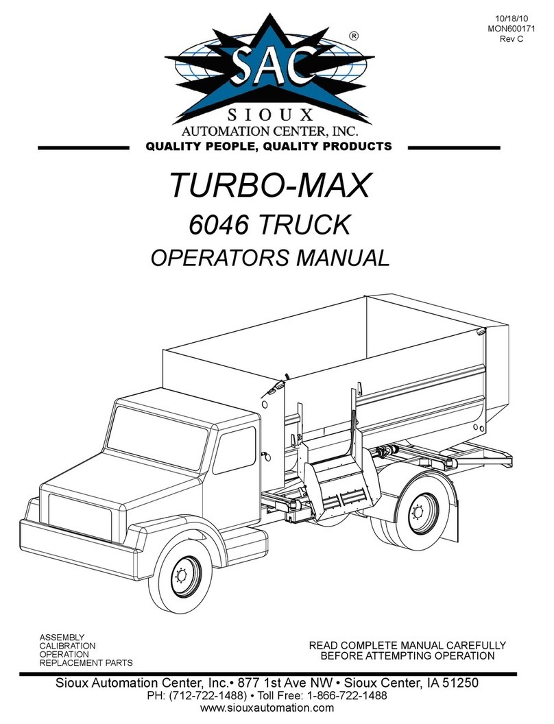
SAC 3600 Series User manual

877 1st Ave. N.W. | Sioux Center, IA 51250 | Toll Free: 1.866.722.1488 | siouxautomation.com
OPERATION
REPLACEMENT PARTS
READ complete manual CAREFULLY
BEFORE attempting operation.
VM600030 REV G 04/01/21
MAXI-MIXER
3600 SERIES TRUCK
OPERATORS MANUAL

Page # 2
877 1st Ave. N.W. | Sioux Center, IA 51250 | Toll Free: 1.866.722.1488 | siouxautomation.com
OPERATION
REPLACEMENT PARTS
READ complete manual CAREFULLY
BEFORE attempting operation.
877 1st Ave. N.W. | Sioux Center, IA 51250 | Toll Free: 1.866.722.1488 | siouxautomation.com
OPERATION
REPLACEMENT PARTS
READ complete manual CAREFULLY
BEFORE attempting operation.
REV DATE BILL OF MATERIALS DESCRIPTION
A 8/9/16 VM900345
SAC56058 & SAC56078
UPDATED TO REV A
ADDED SAC BUMPER OPTIONS
B 3/7/17 REVIEW ALL BOMS REVIEWED AND UPDATED ALL ASSEMBLIES
C 3/28/17 WARRANTY UPDATED WARRANTY SHEET
D 9/27/17 PAGES 67, 99 & 103 ADDED DISCHARGE CHAIN INSTALLATION
ILLUSTRATION AND INSTALLATION NOTES
E 10/16/20 PAGE 48 ADD NOTE FOR VM800341 IN ELECTRICAL KIT
F 11/11/20 VM900254 - PAGES 82 - 85
REPLACE ASSEMBLIES VM700253 AND VM700254
WITH DO3 VALVE ASSEMBLY AND HARNESES
VM800179, VM800240,VM900395 AND VM900396
G 3/31/21 VM900360 AND VM900361
- PAGES 82 - 98
ADD REPTO ASSY AND AUX REPTO ASSEMBLY

Page # 3
877 1st Ave. N.W. | Sioux Center, IA 51250 | Toll Free: 1.866.722.1488 | siouxautomation.com
OPERATION
REPLACEMENT PARTS
READ complete manual CAREFULLY
BEFORE attempting operation.
877 1st Ave. N.W. | Sioux Center, IA 51250 | Toll Free: 1.866.722.1488 | siouxautomation.com
OPERATION
REPLACEMENT PARTS
READ complete manual CAREFULLY
BEFORE attempting operation.
Introduction, General and Contact Information,..........................................................................................................................................4
Customer Reference Information.......................................................................................................................................................................5
Safety Symbols and Signal Words ......................................................................................................................................................................6
Guidelines, Lighting and Marking......................................................................................................................................................................7
Safety Sign Care, Sign Locations......................................................................................................................................................................8-12
Hydraulic, Maintenance .......................................................................................................................................................................................13
Tire Safety, Before Operation ............................................................................................................................................................................14
During Operation ..................................................................................................................................................................................................15
Following Operation, Transport Operations..................................................................................................................................................16
Following a Maintenance Schedule ...............................................................................................................................................................17
Performing Maintenance......................................................................................................................................................................................17
Bolt Torque Data ......... ...........................................................................................................................................................................................18
Pre-Operation Checklist, Hydraulic Pump System ......................................................................................................................................19
Control Console & Display................................................................................................................................................................................ 20-46
Electrical Kits .........................................................................................................................................................................................48-53
Hydraulic Reservior ...............................................................................................................................................................................................54
Front Door Discharge ...........................................................................................................................................................................................55
Troubleshooting .......... .......................................................................................................................................................................................56-57
Mixer Set-up ............................................................................................................................................................................................................58
Mixer Operation ...................................................................................................................................................................................................59-63
Inspection and Adjustments...............................................................................................................................................................................64
Fluids and Lubricants ...........................................................................................................................................................................................65
Conveyor Lubrication and Maintenance .....................................................................................................................................................66-67
Auger Maintenance ............................................................................................................................................................................................68
Hydraulic Filtration ........... ..................................................................................................................................................................................69-72
Hydraulic Cooling System....................................................................................................................................................................................73
Hydro and Auxiliary Hydraulic Assemblies ................................................................................................................................................74-98
Final Assembly .....................................................................................................................................................................................................99-101
Machine Mounts ....................................................................................................................................................................................................102
Discharge Door Assembly...................................................................................................................................................................................103
Restrictor Blade, Viewing Window ...................................................................................................................................................................104
Auger Assemblies ..................................................................................................................................................................................... 105-106
Replacement Auger Installation ......................................................................................................................................................................107
Knife Assemblies ...........................................................................................................................................................................................108
Rear Discharge Door Assembly ........................................................................................................................................................................109
Discharge Assemblies .....................................................................................................................................................................................111-116
Magnetic Deector ................................................................................................................................................................................................117
Rear Bumper and Light Assembly....................................................................................................................................................................119
Front Bumper Assemblies ..............................................................................................................................................................................121-121
Driveline Assemblies .............................................................................................................................................................................................122
Scale Kits ...................................................................................................................................................................................................................123
Remote Control Kit ...........................................................................................................................................................................................124
Remote Camera Kit ...........................................................................................................................................................................................125
Extension Kits ...........................................................................................................................................................................................126
Maxi-Mixer Specication Chart ........................................................................................................................................................................127
Maintenence Record .......................................................................................................................................................................................129-131
Warranty ................................. .................................................................................................................................................................................132
Scale Warranty ........................................................................................................................................................................................................133
TABLE OF CONTENTS

Page # 4
877 1st Ave. N.W. | Sioux Center, IA 51250 | Toll Free: 1.866.722.1488 | siouxautomation.com
OPERATION
REPLACEMENT PARTS
READ complete manual CAREFULLY
BEFORE attempting operation.
877 1st Ave. N.W. | Sioux Center, IA 51250 | Toll Free: 1.866.722.1488 | siouxautomation.com
OPERATION
REPLACEMENT PARTS
READ complete manual CAREFULLY
BEFORE attempting operation.
GENERAL INFORMATION
1. Unless otherwise specied, high-strength (grade 5) (3 radial-line head markings) hex head bolts are used throughout
assembly of this piece of equipment.
2. Whenever terms “LEFT” and “RIGHT” are used in this manual it means from a position behind the mixer box and
facing forward.
3. When placing a parts order, refer to this manual for proper part numbers and place order by PART NO. and DE-
SCRIPTION.
4. Read assembly instructions carefully. Study assembly procedures and all illustrations before you begin assembly.
Note which parts are used in each step.This unit must be assembled in proper sequence or complications will result.
WARNING: TO AVOID PERSONAL INJURY OR DEATH, OBSERVE THE FOLLOWING INSTRUCTIONS:
Never overload. The rating of the chassis or the rating of the mixer, whichever is less, is your max.
Ensure that anybody present is clear before applying power to any machinery used in conjunction with
wagon box or when moving box.
Never allow anyone in, near, or on mixing chamber during mixing, transporting, or unloading of feed.
Thank you for choosing Sioux Automation’s 3600 Series Vertical Mixer to complement your operation. This equipment has been
designed and manufactured to meet the needs of the discriminating buyer for ecient cutting, mixing and feeding.
Safe, ecient and trouble free operation of your mixer requires that you and anyone else who will be operating or maintaining the
machine,readandunderstandtheSafety,Operation,MaintenanceandTroubleshootinginformationcontainedwithintheOperator’s
Manual.
This manual covers the 3600 Series Truck Models by Sioux Automation Center. Keep this manual readily available for reference and
be sure to pass it on to new Operators or Owners. Contact your nearest Sioux Automation Center Dealer or Distributor if you need
assistance or information.
INTRODUCTION
Contact Sioux Automation Center, Inc. at:
877 1st Ave NW
Sioux Center, IA 51250
Phone: (712) 722-1488
Toll Free (866) 722-1488
Fax: (712) 722-1487
Website: www.siouxautomation.com
CONTACT INFORMATION

Page # 5
877 1st Ave. N.W. | Sioux Center, IA 51250 | Toll Free: 1.866.722.1488 | siouxautomation.com
OPERATION
REPLACEMENT PARTS
READ complete manual CAREFULLY
BEFORE attempting operation.
877 1st Ave. N.W. | Sioux Center, IA 51250 | Toll Free: 1.866.722.1488 | siouxautomation.com
OPERATION
REPLACEMENT PARTS
READ complete manual CAREFULLY
BEFORE attempting operation.
SERIAL NUMBER LOCATIONS
Always give your Dealer the Model Number and Serial Number of your Sioux Automation Center 3600 series mixer when or-
dering parts or requesting service or other information. Depending on the type of service, the Serial Numbers of individual
components and/or assemblies will be required. The Serial Number location required for servicing your mixer is shown in
Figure 1 and is located behind the discharge on the drivers side at the base of the mixer. For easy reference, please write this
information in the Customer Reference Information section that follows.
Figure 1 Serial Number Location
CUSTOMER REFERENCE INFORMATION
Model Number:________________________________ Serial Number:____________________
Dealer Name:____________________________________Dealer Phone:______________________
Scale Indicator Model Number:____________________
Scale Indicator Serial Number:____________________
Remote Scale Indicator Serial Number:______________
Other Main Components:_________________________
(e.g. Gearboxes, Hydraulic Motors, etc.) ________________________________________________

Page # 6
877 1st Ave. N.W. | Sioux Center, IA 51250 | Toll Free: 1.866.722.1488 | siouxautomation.com
OPERATION
REPLACEMENT PARTS
READ complete manual CAREFULLY
BEFORE attempting operation.
877 1st Ave. N.W. | Sioux Center, IA 51250 | Toll Free: 1.866.722.1488 | siouxautomation.com
OPERATION
REPLACEMENT PARTS
READ complete manual CAREFULLY
BEFORE attempting operation.
TAKE NOTE! THIS SAFETY ALERT SYMBOL FOUND THROUGHOUT THIS
MANUAL IS USED TO CALL YOUR ATTENTION TO INSTRUCTIONS INVOLVING YOUR PERSONAL
SAFETY AND SAFETY OF OTHERS. FAILURE TO FOLLOW THESE INSTRUCTIONS CAN RESULT IN
INJURY OR DEATH!
THIS SYMBOL MEANS
ATTENTION
BECOME ALERT
YOUR SAFETY IS INVOLVED!
SIGNAL WORDS
Note: use of following signal words DANGER, WARNING, and
CAUTION with safety messages. Appropriate signal word for
each has been selected using following guidelines:
DANGER:
Indicates an imminently hazardous situation that, if not
avoided, will result in serious injury or death. This signal word
is to be limited to most extreme situations typically for machine
components which, for functional purposes, cannot be guarded.
WARNING:
Indicates a potentially hazardous situation that, if not avoided,
could result in serious injury or death, and includes hazards that
are exposed when guards are removed. It may also be used to
alert against unsafe practices.
CAUTION:
Indicates a potentially hazardous situation that, if not avoided,
may result in minor or moderate injury. It may also be used to
alert against unsafe practices.
If you have questions not answered in this manual, require additional copies, or if your manual is damaged, please contact your dealer
or Sioux Automation Center Inc., 877 1st Ave NW, Sioux Center, IA 51250, ph: (712) 722-1488 or
Toll Free: 1-866-722-1488, Fax: (712) 722-1487 http://www.siouxautomation.com
SAFETY

Page # 7
877 1st Ave. N.W. | Sioux Center, IA 51250 | Toll Free: 1.866.722.1488 | siouxautomation.com
OPERATION
REPLACEMENT PARTS
READ complete manual CAREFULLY
BEFORE attempting operation.
877 1st Ave. N.W. | Sioux Center, IA 51250 | Toll Free: 1.866.722.1488 | siouxautomation.com
OPERATION
REPLACEMENT PARTS
READ complete manual CAREFULLY
BEFORE attempting operation.
SAFETY...YOU CAN LIVE WITH IT
EQUIPMENT SAFETY GUIDELINES
YOU are responsible for the SAFE operation and maintenance of your 3600 series mixer. YOU must ensure that
YOU and ANYONE else who is going to operate, maintain, or work around the mixer be familiar with the operating
and maintenance procedures and related SAFETY information contained in this manual. This manual will take you
step-by-step through your working day and alerts you to safety practices that should be adhered to while operating
the machine.
Remember, YOU are the key to SAFETY. Good safety practices not only protect you but also the people around you.
Make these practices a working part of your safety program. Be certain that EVERYONE operating this equipment is
familiar with the recommended operating and maintenance procedures and follows all the safety precautions. All
accidents can be avoided. Do not risk injury or death by ignoring good safety practices.
• VerticalMixerownersmustgiveoperatinginstructionstooperatorsoremployeesbeforeallowingthem
to operate the machine, and at least annually thereafter.
• ThemostimportantsafetydeviceonthisequipmentisaSAFE OPERATOR. It is the operator’s
responsibility to read and understand ALL Safety and Operating instructions in the manual and
to follow them.
• SiouxAutomationCenter,Inc.feelsthatapersonwhohasnotreadandunderstoodalloperatingand
safety instructions is not qualied to operate the machine. An untrained operator exposes himself
and bystanders to possible serious injury or death.
• Donotmodifytheequipmentinanyway.Unauthorizedmodicationmayimpairthefunctionand/or
safety and could aect the life of the equipment.
• ThinkSAFETY!WorkSAFELY!
In order to provide a better view, certain illustrations in this manual may show an assembly with a safety shield
removed. However, equipment should never be operated in this condition. Keep all shields in place. If shield removal
becomes necessary for repairs, replace shield prior to use.
Replace any caution, warning, danger or instruction safety decal that is not readable or is missing. Location of such
decals are indicated in this booklet.
Do not attempt to operate this equipment under the inuence of alcohol or drugs.
• Onlytrained,competentpersonsshalloperatetheverticalmixer.Anuntrainedoperatorisnot
qualied to operate the machine.
• Havearst-aidkitavailableforuseshouldtheneedariseandknowhowtouseit.
• Provideareextinguisherforuseincaseofare.Storeinahighlyvisibleplace.
LIGHTING AND MARKING
It is the responsibility of customer to know lighting and marking requirements of local highway authorities and to
install and maintain equipment to provide compliance with regulations. Add extra lights when transporting at night
or during periods of limited visibility.
SAFETY

Page # 8
877 1st Ave. N.W. | Sioux Center, IA 51250 | Toll Free: 1.866.722.1488 | siouxautomation.com
OPERATION
REPLACEMENT PARTS
READ complete manual CAREFULLY
BEFORE attempting operation.
877 1st Ave. N.W. | Sioux Center, IA 51250 | Toll Free: 1.866.722.1488 | siouxautomation.com
OPERATION
REPLACEMENT PARTS
READ complete manual CAREFULLY
BEFORE attempting operation.
SAFETY SIGN CARE
• Keepsafetysignscleanandlegibleatalltimes.
• Replacesafetysignsthataremissingorhavebecomeillegible.
• Replacedpartsthatdisplayedsafetysignsshouldalsodisplaycurrentsafetysigns.
• Safetysignsareavailablefromyourdistributor,dealerpartsdepartment,orfactory.
• Howtoinstallsafetysigns:
• Besurethatinstallationareaiscleananddry.
• Decideonexactpositionbeforeyouremovebackingpaper.
• Removesmallestportionofsplitbackingpaper.
• Aligndecaloverspeciedareaandcarefullypresssmallportionwithexposedstickybackinginplace.
• Slowlypeelbackremainingpaperandcarefullysmoothremainingportionofdecalintoplace.
• Smallairpocketscanbepiercedwithapinandsmoothedoutusingpieceofdecalbackingpaper.
SAFETY

Page # 9
877 1st Ave. N.W. | Sioux Center, IA 51250 | Toll Free: 1.866.722.1488 | siouxautomation.com
OPERATION
REPLACEMENT PARTS
READ complete manual CAREFULLY
BEFORE attempting operation.
877 1st Ave. N.W. | Sioux Center, IA 51250 | Toll Free: 1.866.722.1488 | siouxautomation.com
OPERATION
REPLACEMENT PARTS
READ complete manual CAREFULLY
BEFORE attempting operation.
Types of decals and safety signs with locations are shown in illustration below. Good safety requires that you fa-
miliarize yourself with the various decals, type of information provided, and the areas that require your awareness.
Think SAFETY! Work SAFETY!
DECAL A
BOTH RIGHT
AND LEFT
SIDES
DECAL B & C
LEFT REAR VIEW
IF EQUIPPED WITH REAR DOOR
RIGHT FRONT VIEW
DECAL D
DECAL B & C
DECAL D
REAR OF CONVEYOR
ON LEFT HAND SIDE RIGHT AND LEFT SIDE OF PUMP
HOOD LOCATED AT
THE FRONT OF THE TRUCK
DECAL E DECAL G DECAL F
SAFETY
SAFETY SIGN LOCATIONS:

Page # 10
877 1st Ave. N.W. | Sioux Center, IA 51250 | Toll Free: 1.866.722.1488 | siouxautomation.com
OPERATION
REPLACEMENT PARTS
READ complete manual CAREFULLY
BEFORE attempting operation.
877 1st Ave. N.W. | Sioux Center, IA 51250 | Toll Free: 1.866.722.1488 | siouxautomation.com
OPERATION
REPLACEMENT PARTS
READ complete manual CAREFULLY
BEFORE attempting operation.
SAFETY SIGN LOCATIONS
DECAL ‘A’
DECAL ‘B’
SAFETY
DWG. NO.
SCALE
A
B
C
D
DO NOT SCALE DRAWING
1234567
8
A
B
C
D
1
2345678
DWG. NO.
DEC107 REV
AS NOTED
-
FINISH
MANUFACTURING PROCESS
32.18 2
IN
SURFACE AREA
LBS
REV.
A
SAC MATERIAL
WEIGHT
0.00
DATE
DATE
IRST AV
1
ENG.
THIRD ANGLE
IN PART OR AS A WHOLE WITHOUT THE WRITTEN PERMISSION OF SIOUX AUTOMATION CENTER, INC. IS PROHIBITED.
SIZE
PROJECTION
THE INFORMATION CONTAINED IN THIS DRAWING IS THE SOLE PROPERTY OF SIOUX AUTOMATION CENTER, INC. ANY REPRODUCTION
1
1
OF
SHEET
SPECIFIED
12-03
DECAL,WARNING,CHAIN,EXPOSED
877 F
MATERIAL DESCRIPTION
ANGULAR
.005
AS NOTED
CV
DFTM.
1:1
GENERAL TOLERANCES
DEC107
E NW, SIOUX CENTER, IA 51250
.03
.XXX =
.XX =
SIOUX AUTOMATION CENTER, INC.
DIMENSIONS ARE IN INCHES
TOLERANCES UNLESS
AS NOTED
REVISIONS
ECN REV. DESCRIPTION DATE BY
PINCH POINT
4) USE STANDARD SHAPE FOR CHAIN
UV RESISTANT COATING.
1.) TEXT : ARIAL .15" TALL
2.) MATERIAL 5-8 YEAR CAST VINYL
WITH PERMANENT PRESSURE SENSITIVE
ADHESIVE.
3.) APPLY CLEAR 1 MIL OVER LAMINATE
WARNING BACKGROUND ORANGE
ALL OTHER BACKGROUND WHITE
TEXT AND DRAWING COLOR IS BLACK
4.00
4.00
DECAL ‘C’

Page # 11
877 1st Ave. N.W. | Sioux Center, IA 51250 | Toll Free: 1.866.722.1488 | siouxautomation.com
OPERATION
REPLACEMENT PARTS
READ complete manual CAREFULLY
BEFORE attempting operation.
877 1st Ave. N.W. | Sioux Center, IA 51250 | Toll Free: 1.866.722.1488 | siouxautomation.com
OPERATION
REPLACEMENT PARTS
READ complete manual CAREFULLY
BEFORE attempting operation.
SAFETY SIGN LOCATIONS
DECAL ‘D’
LOCATED BY BLOCK
MANIFOLD AND PUMPS
DECAL ‘E’
LOCATED BY HYDRO PUMPS
DECAL ‘F’
LOCATED BY HYDRO PUMPS
DECAL ‘G’
HYDRAULIC OIL HEALTH HAZARD
WARNING DECAL
LOCATED BY HYDRO PUMPS
SAFETY
DEC118

Page # 12
877 1st Ave. N.W. | Sioux Center, IA 51250 | Toll Free: 1.866.722.1488 | siouxautomation.com
OPERATION
REPLACEMENT PARTS
READ complete manual CAREFULLY
BEFORE attempting operation.
877 1st Ave. N.W. | Sioux Center, IA 51250 | Toll Free: 1.866.722.1488 | siouxautomation.com
OPERATION
REPLACEMENT PARTS
READ complete manual CAREFULLY
BEFORE attempting operation.
E NW, SIOUX CENTER, IA 51250
A
B
C
D
DO NOT SCALE DRAWING
1234567
8
A
B
C
D
1
2345678
DWG. NO.
VM800310-1
DWG. NO. -
FINISH
MANUFACTURING PROCESS
2
IN
SURFACE AREA
LBS
MATERIAL DESCRIPTION
REV.
A
SAC MATERIAL
WEIGHT DATE
DATEENG.
1
PROJECTION
THIRD ANGLE
IN PART OR AS A WHOLE WITHOUT THE WRITTEN PERMISSION OF SIOUX AUTOMATION CENTER, INC. IS PROHIBITED.
REV
1-15
THE INFORMATION CONTAINED IN THIS DRAWING IS THE SOLE PROPERTY OF SIOUX AUTOMATION CENTER, INC. ANY REPRODUCTION
SIZE
1
OF
1
1:32
SPECIFIED
GENERAL TOLERANCES
877 F
ANGULAR
SHEET
.005
AP
AS NOTED
DFTM.
VM800310-1
.XXX =
.03
-
KIT,3675,BASE,TRK
IRST AV
.XX =
SIOUX AUTOMATION CENTER, INC
.
DIMENSIONS ARE IN INCHES
TOLERANCES UNLESS
SCALE
REVISIONS
ECN REV. DESCRIPTION DATE BY
3
1
2
.83
17.17
FROM TOP
OF BOX
1.00
FROM TOP OF BOX
SAFETY SIGN LOCATIONS
SAFETY
MODEL PART # DESCRIPTION
3640 VM900275 3640 DECAL KIT
3645 VM900276 3645 DECAL KIT
3650 VM900277 3650 DECAL KIT
3655 VM900278 3655 DECAL KIT
3670 VM900279 3670 DECAL KIT
NOTE: DECAL KITS SHOWN IN THE TABLE INCLUDE ALL THREE OF THE ITEMS
SHOWN IN THE FIGURE. IF INDIVIDUAL DECALS ARE DESIRED, THE LARGER TABLE
PROVIDES THOSE PART NUMBERS.
ITEM
#PART #
VM900275 QTY
MODEL 3640
VM900276 QTY
MODEL 3645
VM900277 QTY
MODEL 3650
VM900278 QTY
MODEL 3655
VM900279 QTY
MODEL 3670
VM900280 QTY
MODEL 3675
VM900281 QTY
MODEL 3680
VM900282 QTY
MODEL 3690
VM900283 QTY
MODEL 36100
VM900284 QTY
MODEL 36125
DESCRIPTION
1
DEC507 2 2 0 0 0 0 0 0 0 0 STRIPE DECAL
DEC488 0 0 2 2 0 0 0 0 0 0 STRIPE DECAL
DEC490 0 0 0 0 2 2 2 2 2 2 STRIPE DECAL
2DEC626 2 2 2 2 0 0 0 0 0 0 SAC LOGO
DEC625 0 0 0 0 2 2 2 2 2 2 SAC LOGO
3
DEC673 2 0 0 0 0 0 0 0 0 0 3640 DECAL
DEC674 0 2 0 0 0 0 0 0 0 0 3645 DECAL
DEC675 0 0 2 0 0 0 0 0 0 0 3650 DECAL
DEC676 0 0 0 2 0 0 0 0 0 0 3655 DECAL
DEC677 0 0 0 0 2 0 0 0 0 0 3670 DECAL
DEC678 0 0 0 0 0 2 0 0 0 0 3675 DECAL
DEC679 0 0 0 0 0 0 2 0 0 0 3680 DECAL
DEC680 0 0 0 0 0 0 0 2 0 0 3690 DECAL
DEC681 0 0 0 0 0 0 0 0 2 0 36100 DECAL
DEC682 0 0 0 0 0 0 0 0 0 2 36125 DECAL
MODEL PART # DESCRIPTION
3675 VM900280 3675 DECAL KIT
3680 VM900281 3680 DECAL KIT
3690 VM900282 3690 DECAL KIT
36100 VM900283 36100 DECAL
KIT

Page # 13
877 1st Ave. N.W. | Sioux Center, IA 51250 | Toll Free: 1.866.722.1488 | siouxautomation.com
OPERATION
REPLACEMENT PARTS
READ complete manual CAREFULLY
BEFORE attempting operation.
877 1st Ave. N.W. | Sioux Center, IA 51250 | Toll Free: 1.866.722.1488 | siouxautomation.com
OPERATION
REPLACEMENT PARTS
READ complete manual CAREFULLY
BEFORE attempting operation.
HYDRAULIC SAFETY
• Makesurethatallcomponentsinthehydraulicsystemarekeptingoodconditionandareclean.
• Replaceanyworn,cut,abraded,attened,orcrimpedhosesormetallinesimmediately.
• Relievepressurebeforeworkingonhydraulicsystems.
• Donotattemptanymakeshiftrepairstothehydraulicttingsorhosesbyusingtape,clamps,orcements.
The hydraulic system operates under extremely high pressure. Such repairs will fail suddenly and create a
hazardous and unsafe condition.
• Wearproperhandandeyeprotectionwhensearchingforahigh-pressurehydraulicleak.Useapieceofwood
or cardboard as a backstop instead of hands to isolate and identify a leak.
• Ifinjuredbyaconcentratedhigh-pressurestreamofhydraulicuid,seekmedicalattentionimmediately.
Serious infection or toxic reaction can develop from hydraulic uid piercing the skin surface.
• Beforeapplyingpressuretothesystem,makesureallcomponentsaretightandthatlines,hoses,and
couplings are not damaged.
MAINTENANCE SAFETY
• FollowALLtheoperating,maintenance,andsafetyinformationinthemanual.
• Supportthemachinewithblocksorsafetystandswhenchangingtiresorworkingbeneath.
• Followgoodshoppractices:
- Keep service areas clean and dry.
- Be sure electrical outlets and tools are properly grounded.
- Use adequate lighting for the job at hand.
• Useonlytools,jacks,andhoistsofsucientcapacityforthejob.
• Placecontrolsinneutral,stopengine,setparkbrake,removeignitionkey,andwaitforallmovingpartstostop
before servicing, adjusting, repairing, or unplugging.
• Relievepressurefromthehydrauliccircuitbeforeservicing.
• Makesureallguardsareinplaceandproperlysecuredwhenmaintenanceworkiscompleted.
• Beforeapplyingpressuretoahydraulicsystem,makesurealllines,ttings,andcouplersaretightandin
good condition.
• Keephands,feet,hair,andclothingawayfromallmovingand/orrotatingparts.
• Maintainfastenersinrunninggearsystemsattheirspeciedtorqueatalltimes.
• Cleartheareaofbystanders,especiallysmallchildren,whencarryingoutanymaintenance,repairs,or
making any adjustments.
SAFETY

Page # 14
877 1st Ave. N.W. | Sioux Center, IA 51250 | Toll Free: 1.866.722.1488 | siouxautomation.com
OPERATION
REPLACEMENT PARTS
READ complete manual CAREFULLY
BEFORE attempting operation.
877 1st Ave. N.W. | Sioux Center, IA 51250 | Toll Free: 1.866.722.1488 | siouxautomation.com
OPERATION
REPLACEMENT PARTS
READ complete manual CAREFULLY
BEFORE attempting operation.
TIRE SAFETY
• Failuretofollowproperprocedureswhenmountingatireonarimcanproduceanexplosionwhichmay
result in a serious injury or death.
• Donotattempttomountatireunlessyouhaveproperequipmentandexperiencetodojob.
• Inatingorservicingtirescanbedangerous.Wheneverpossible,trainedpersonnelshouldbecalledto
service and/or mount tires.
• Alwaysorderandinstalltiresandwheelswithappropriatetypeandloadcapacitytomeetorexceed
anticipated weight to be placed on the equipment.
BEFORE OPERATION:
• Carefullystudyandunderstandthismanual.
• Donotwearloose-ttingclothingwhichmaycatchinmovingparts.
• Alwayswearprotectiveclothingandsubstantialshoes.
• Itisrecommendedthatsuitablehearingandeyeprotectionbeworn.
• Operatormaycomeincontactwithcertainmaterialswhichmayrequirespecicsafetyequipmentrelativeto
handling of such materials.
• Keepwheelandlugnutstightenedtospeciedtorque.
• Assurethatalltiresareinatedevenly.
• Giveunitavisualinspectionforanyloosebolts,wornparts,orcrackedwelds,andmakenecessaryrepairs.
Follow maintenance safety instructions included in this manual.
• Besuretherearenotoolslyingonorinequipment
• Donotuseunituntilyouaresurethatareaisclear,especiallyaroundchildrenandanimals.
• Don’thurrylearningprocessortakeunitforgranted.Easeintoitandbecomefamiliarwithyournewequipment.
• Practiceoperationofyourequipmentanditsattachments.Completelyfamiliarizeyourselfandother
operators with its operation before using.
• Makesurethatbrakesareevenlyadjusted(ifequippedwithbrakes).
• Stayawayfromunloadingdoorandconveyordischargewhenunloadingormoving.
SAFETY

Page # 15
877 1st Ave. N.W. | Sioux Center, IA 51250 | Toll Free: 1.866.722.1488 | siouxautomation.com
OPERATION
REPLACEMENT PARTS
READ complete manual CAREFULLY
BEFORE attempting operation.
877 1st Ave. N.W. | Sioux Center, IA 51250 | Toll Free: 1.866.722.1488 | siouxautomation.com
OPERATION
REPLACEMENT PARTS
READ complete manual CAREFULLY
BEFORE attempting operation.
DURING OPERATION
• Bewareofbystanders,PARTICULARLYCHILDREN!Alwayslookaroundtomakesurethatitissafeto
start the engine or move the unit. This is particularly important with higher noise levels and quiet cabs,
as you may not hear people shouting.
• NOPASSENGERSALLOWED-Donotcarrypassengersanywhereonorintheequipment.
• Keephandsandclothingclearofmovingparts.
• Donotclean,lubricate,oradjustyourequipmentwhileitismoving.
• Whenhaltingoperation,evenperiodically,setthevehicle’sbrakes,disengagehydraulicpumps,shuto
engine, and remove ignition key.
• Beespeciallyobservantofoperatingareaandterrain.Watchforholes,rocks,orotherhiddenhazards.Always
inspect area prior to operation.
- DO NOT operate near edge of drop-o or banks.
- DO NOT operate on steep slopes as overturn may result.
- Operate up and down (not across) intermediate slopes. Avoid sudden starts and stops.
• Pickthemostlevelpossibleroutewhentransportingacrosselds.Avoidedgesofditches,gullies,andsteep
hillsides.
• Beextracarefulwhenworkingoninclines.
• Maneuverthevehicleatsafespeeds.
• Avoidoverheadwiresorotherobstacles.Contactwithoverheadlinescouldcauseseriousinjuryordeath.
• Avoidloosegravel,rocks,andholes;theycanbedangerousforequipmentoperationor
movement.
• Allowforunitlengthwhenmakingturns.
• Donotwalkorworkunderraisedcomponentsorattachmentsunlesssecurelypositionedandblocked.
• Keepallbystanders,pets,andlivestockclearofworkarea.
• Operatethemixerfromoperatorsseatonly.
• Neverstandalongsideofunitwithenginerunningorattempttostartengineand/oroperatemachinewhile
standing alongside of unit.
• Neverleaverunningequipmentunattended.
• Asaprecaution,alwaysrecheckhardwareonequipmentfollowingevery100hoursofoperation.Correctall
problems. Follow maintenance safety procedures.
• Neverhandfeedmaterialsintomixerwhileitisrunning.Rotatingaugersinsidemixermaynotbevisiblefrom
the loading point, and may cut or grab hands, clothing, or material being loaded, causing severe injury.
Always stop tractor engine before hand loading materials.
• Donotallowoperationofthisunitbyinexperiencedorunqualiedpeople.Keepallunqualiedpeopleaway
from mixer during operation. Operators of this unit must be alert and use good judgement at all times. Operator
should not climb on ladder or any part of the mixer when loading, mixing, or discharging material.
• Besuretheinsideofthemixerisclearofanyobstructionbeforeoperating.
SAFETY

Page # 16
877 1st Ave. N.W. | Sioux Center, IA 51250 | Toll Free: 1.866.722.1488 | siouxautomation.com
OPERATION
REPLACEMENT PARTS
READ complete manual CAREFULLY
BEFORE attempting operation.
877 1st Ave. N.W. | Sioux Center, IA 51250 | Toll Free: 1.866.722.1488 | siouxautomation.com
OPERATION
REPLACEMENT PARTS
READ complete manual CAREFULLY
BEFORE attempting operation.
• Usecautionwhenworkingaroundthedischargearea.Stayclearoftheslideoutdischarge.Thisis
controlled from the cab and could operate without warning, creating pinch points which could cause severe
injury or death. Always stop engine before working close to the discharge area.
• Neverattempttoreleasejammedmaterialsorcleanmaterialsfromanyareaofthemixerordischargechutewith
out stopping engine and disengaging drive line rst. Moving parts can be hidden by materials, and stopped parts
can start unexpectedly, causing severe injury. Always stop truck engine and relieve hydraulic pressure before
attempting to remove jammed material or to clean.
• Neverputarmsorfeetinsideunit,powerchute,ordischargedooropening,norclimbonorinthemixerwhileitis
running. NEVER allow anyone to position themselves over or near the top of the mixer while it is running.
Rotating augers and sprockets can grab clothing or create pinch points which can cause severe injury or death
to the operator or bystanders. Always stop the engine so that the mixer can not be accidentally turned on while
inspecting, servicing, repairing, or cleaning the mixer.
• Followingoperation,setbrakes,shutoengineandremovetheignitionkey.
• Storeunitinanareaawayfromhumanactivity.
• Donotparkequipmentwhereitwillbeexposedtolivestockforlongperiodsoftime.Damageandlivestockinjury
could result.
• Donotpermitchildrentoplayonoraroundstoredunit.
• Makesureallparkedmachinesareonahard,levelsurfaceandengageallsafetydevices.
• Wheelchocksmaybeneededtopreventunitfromrolling.
FOLLOWING OPERATION
HIGHWAY AND TRANSPORT OPERATIONS
• Adoptsafedrivingpractices:
- Always drive at a safe speed relative to local conditions, ensure that your speed is low enough for an
emergency stop. Keep speed to a minimum.
- Reduce speed prior to turns to avoid risk of overturning.
- Donotdrinkanddrive!
• Comply with state and local laws governing highway safety on public roads.
• Use approved accessory lighting, ags and necessary warning devices to protect operators of other vehicles on highway
during transport. Various safety lights and devices are available from your dealer.
• Be a safe and courteous driver.
• Be observant of bridge load ratings. Do not cross bridges rated lower than gross weight at which you are operating.
• Make sure all the lights and reectors that are required by the local highway and transport authorities are in place, are
clean and can be seen clearly by all overtaking and oncoming trac.
• Watch for obstructions overhead and side to side while transporting.
• Always operate equipment in a position to provide maximum visibility. Make allowances for increased length and weight
of equipment when making turns, stopping unit, etc.
DURING OPERATION
SAFETY

Page # 17
877 1st Ave. N.W. | Sioux Center, IA 51250 | Toll Free: 1.866.722.1488 | siouxautomation.com
OPERATION
REPLACEMENT PARTS
READ complete manual CAREFULLY
BEFORE attempting operation.
877 1st Ave. N.W. | Sioux Center, IA 51250 | Toll Free: 1.866.722.1488 | siouxautomation.com
OPERATION
REPLACEMENT PARTS
READ complete manual CAREFULLY
BEFORE attempting operation.
It is the Owner/Operator’s responsibility to operate, lubricate, maintain, and store the machine in accordance with all instruc-
tions and safety procedures. While machine operating conditions will vary, an eective maintenance schedule can be followed
when considering the following points.
Remember, the guidelines established in this manual are general. All maintenance and service work is not limited to these
guidelines. If you have any questions or concerns, please contact your Sioux Automation Dealer or Distributor. Points to
Consider in Developing an Eective Maintenance Schedule:
• Will the machine be operating at full capacity (i.e. mixing chamber full, high-density ration)? For example, a heavy
load would yield a ration density equal to or greater than 30 lbs/ft3.
• How long will the machine be operated each day? Depending on the operation, some customers require as little as
2 hours a day, while others require in excess of 16 hours a day.
• Will the machine be transported long distances? If the answer is yes, this would require more attention to components
such as wheels and hubs.
• Will the machine be transported over rough terrain? Will the same terrain have conditions such as mud, sand, water, etc.?
• Will the machine be exposed to extreme temperatures (ambient air temperature)? This can be interpreted as hot or
cold, or sudden changes from hot to cold or vice versa. This may aect components such as the machine lubricants,
among others.
• Will there be dirty and dusty conditions present? While the machine is designed for these parameters, special attention
to items such as breathers is required.
• Will there be any foreign matter entering the mixing chamber? Depending on the operation, it may be dicult to
eliminate foreign matter such as rocks, stones, steel, wood, etc. However, these items can place added wear on com-
ponents such as the mixing chamber walls, auger assembly, and auger knives.
FOLLOWING AN EFFECTIVE MAINTENANCE SCHEDULE
PERFORMING MAINTENANCE
• Make sure there is plenty of ventilation. Never operate engine in a closed building. Exhaust fumes may cause asphyxiation.
• Before working on this machine, stop the vehicle, set brakes, shut o engine and remove ignition key.
• Always use safety support and block wheels. Never use a jack to support machine.
• Always use proper tools or equipment for job at hand.
• Use extreme caution when making adjustments.
• Never use your hands to locate a hydraulic leak on attachments. Use a small piece of cardboard or wood. Hydraulic uid
escaping under pressure can penetrate skin.
• Openings in skin and minor cuts are susceptible to infection from hydraulic uid. Without immediate medical treatment,
serious infection and reactions can occur.
• When disconnecting hydraulic lines, shut o hydraulic supply and relieve all hydraulic pressure.
• Replace all shields and guards after servicing and before moving.
• After servicing, be sure all tools, parts and service equipment are removed.
• Do not allow grease or oil to build up on any steps or platform.
• When replacing bolts, refer to owners manual.
• Refer to bolt torque chart for head identication marking.
• Where replacement parts are necessary for periodic maintenance and servicing, genuine factory replacement parts must
be used to restore your equipment to original specications. Manufacturer will not claim responsibility for use of unap-
proved parts or accessories and other damages as a result of their use.
• If equipment has been altered in any way from original design, manufacturer does not accept any liability for injury or
warranty.
• A re extinguisher and rst aid kit should be kept readily accessible while performing maintenance on this equipment.
MAINTENANCE

Page # 18
877 1st Ave. N.W. | Sioux Center, IA 51250 | Toll Free: 1.866.722.1488 | siouxautomation.com
OPERATION
REPLACEMENT PARTS
READ complete manual CAREFULLY
BEFORE attempting operation.
877 1st Ave. N.W. | Sioux Center, IA 51250 | Toll Free: 1.866.722.1488 | siouxautomation.com
OPERATION
REPLACEMENT PARTS
READ complete manual CAREFULLY
BEFORE attempting operation.
TORQUE DATA FOR STANDARD NUTS, BOLTS, AND CAPSCREWS.
Tighten all bolts to torques specied in chart unless otherwise noted. Check tightness of bolts periodically, using bolt
chart as guide. Replace hardware with same grade bolt.
NOTE: Unless otherwise specied, high-strength Grade 5 hex bolts are used throughout assembly of equipment.
Bolt Torque for Standard bolts *
GRADE 2 GRADE 5 GRADE 8
“A” lb-ft (N.m) lb-ft (N.m) lb-ft (N.m)
1/4” 6 (8) 9 (12) 12 (16)
5/16” 10 (13) 18 (25) 25 (35)
3/8” 20 (27) 30 (40) 45 (60)
7/16” 30 (40) 50 (70) 80 (110)
1/2” 45 (60) 75 (100) 115 (155)
9/16” 70 (95) 115 (155) 165 (220)
5/8” 95 (130) 150 (200) 225 (300)
3/4” 165 (225) 290 (390) 400 (540)
7/8” 170 (230) 420 (570) 650 (880)
1” 225 (300) 630 (850) 970 (1310)
Torque gures indicated are valid for non-greased
or non-oiled threads and heads unless otherwise
specfied. Therefore, do not grease or oil bolts
or capscrews unless otherwise specied in this
manual. When using locking
elements, increase torque values
by 5%.
* GRADE or CLASS value for bolts and capscrews
are identied by their head markings.
Torque Specications
CLASS 8.8 CLASS 9.8 CLASS 10.9
“A” lb-ft (N.m) lb-ft (N.m) lb-ft (N.m)
6 9 (13) 10 (14) 13 (17)
7 15 (21) 18 (24) 21 (29)
8 23 (31) 25 (34) 31 (42)
10 45 (61) 50 (68) 61 (83)
12 78 (106) 88 (118) 106 (144)
14 125 (169) 140 (189) 170 (230)
16 194 (263) 216 (293) 263 (357)
18 268 (363) -- -- 364 (493)
20 378 (513) -- -- 515 (689)
22 516 (699) -- -- 702 (952)
24 654 (886) -- -- 890 (1206)
Bolt Torque for Metric bolts *
GRADE-2 GRADE-5 GRADE-8
CLASS 8.8 CLASS 9.8 CLASS 10.9
8.8 10.9
9.8
BOLT TORQUE

Page # 19
877 1st Ave. N.W. | Sioux Center, IA 51250 | Toll Free: 1.866.722.1488 | siouxautomation.com
OPERATION
REPLACEMENT PARTS
READ complete manual CAREFULLY
BEFORE attempting operation.
877 1st Ave. N.W. | Sioux Center, IA 51250 | Toll Free: 1.866.722.1488 | siouxautomation.com
OPERATION
REPLACEMENT PARTS
READ complete manual CAREFULLY
BEFORE attempting operation.
PREOPERATION CHECKLIST
Ecient and safe operation of your Sioux Automation 3600 series mixer requires that each operator reads and understands
all the operating procedures and all related safety precautions outlined in this section. A pre-operation checklist is provided
for the operator. It is important for both the personal safety and maintaining the good mechanical condition of the machine
that this checklist is followed.
Before operating the machine the following areas should be checked o:
1. Lubricate the machine as needed.
2. Use only a truck of adequate power and capacity to operate the machine.
3. Check the hydraulic system. Be sure that the hydraulic reservoir in the truck is lled to the required specications.
4. Be sure there are no leaks on the planetary gearboxes. Stop leaks before continuing.
5. Inspect all hydraulic lines, hoses, ttings, and couplers for tightness.
6. Check the tires to be sure that they are inated to the specied pressure.
7. Check that the auger rotates freely. Remove all string, twine, or other entangled material.
8. Check that the PTO driveline is locked to the truck’s crank shaft for front mounted pumps.
9. Close and secure all guards and safety devices.
HYDRAULIC PUMP SYSTEM
Each auger is powered by a hydrostatic pump which is attached to a pump drive and powered by a single driveshaft from the
engine. The pumps can be set up for either CCW (counter clockwise) or CW (clockwise) rotation. Typically, if the pumps are
mounted in front of the engine, CW pumps are installed and CCW pumps are used if the pumps are installed behind the engine.
Each hydrostatic pump is actuated by an electronic valve which is operated from controls in the cab. Each hydro can be con-
trolled independently.
Located on the end of each of the hydrostatic pumps is a single auxiliary hydraulic gear pump. The pumps are powered by
the main driveline for the machine which ensures hydraulic power is available at all times provided that the truck engine is
running. The auxiliary pumps provide hydraulic uid power to components such as the unloading door(s) and the dis-
charge conveyor. The auxiliary pumps are designed for minimal maintenance and service.
AUXILARY PUMP SYSTEM
HYDRO DRIVE
HYDRO DRIVE
DIP STICK
AUXILLIARY
PUMPS
SYSTEMS
HYDRO PUMPS

Page # 20
877 1st Ave. N.W. | Sioux Center, IA 51250 | Toll Free: 1.866.722.1488 | siouxautomation.com
OPERATION
REPLACEMENT PARTS
READ complete manual CAREFULLY
BEFORE attempting operation.
877 1st Ave. N.W. | Sioux Center, IA 51250 | Toll Free: 1.866.722.1488 | siouxautomation.com
OPERATION
REPLACEMENT PARTS
READ complete manual CAREFULLY
BEFORE attempting operation.
CONTROL CONSOLE AND DISPLAY
CONTROLS
Page | 1
Maxi-Mixer
3600 Series Truck
Electronic Control Unit Operators Manual
This Operator’s Manual is a supplement to the main 3600 Series Truck Operators Manual. This operator’s manual
will provide information on the operation of the electronic control system of the truck, troubleshooting points,
specific operator settings, and operation of the system in a feeding environment.
Before attempting to operate the system, this supplementary manual should be read and completely understood
for safe, efficient, and trouble free operation of the mixer. The electronic control of the 3600 Series Truck is a
sophisticated system which allows the operator to change initial settings and also provides safeguards in the event
of mechanical or hydraulic failure. The following pages will step through the operation of the system and
troubleshooting points.
The control system is powered when the truck key is in the ON or ACC position. User settings can be changed
without the truck running, and any settings will be saved in the system when the truck key is in the OFF position or
when the truck batteries are disconnected.
*NOTE: IN THE EVENT THAT WELDING ON THE MIXER OR TRUCK CHASSIS NEEDS TO BE PERFORMED,
THE TRUCK BATTERIES, ALL AUXILIARY POWER SOURCES, AND THE SCALE POWER MUST BE
DISCONNECTED TO PREVENT DAMAGE TO COMPONENTS. IF NOT, SERIOUS EQUIPMENT
MALFUNCTIONS COULD OCCUR.
DISPLAY SCREEN FUNCTIONS
When the truck is powered up and running, the display will default to the Operation screen (Figure 1) which shows
critical system information at a quick glance. Navigation through the display is done using the touch screen or the
soft touch keys on the outer edges of the display that corresponds to the icons next to them.
Figure 1
Table of contents
Other SAC Truck manuals
Popular Truck manuals by other brands

UralAZ
UralAZ URAL-4320-02 Service manual

Trane
Trane Thermo King TriPac Envidia Operator's manual

AMOG
AMOG D'AVINO 120TW user manual

EINHELL
EINHELL TC-PT 2500 Original operating instructions

freightliner
freightliner Custom Classic MT45 2022 Maintenance manual

TOOLCRAFT
TOOLCRAFT 1933087 operating instructions