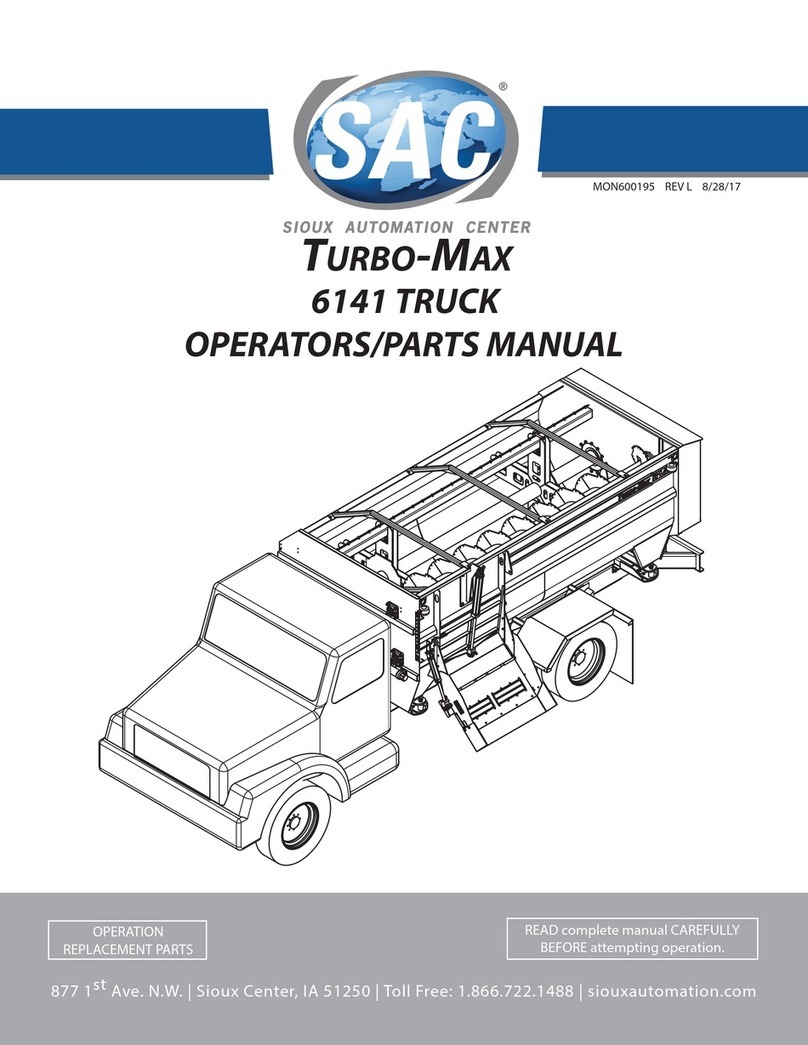
SAC MaxiMixer 2050 User manual

www.siouxautomation.com MON600127
12/7/04 $15
MaxiMixer
MODEL 2050
OPERATION AND
MAINTENANCE MANUAL
877 1st. AVE. NW Sioux Center, IA. 51250 Iowa 1-712-722-1488


TAKE NOTE! THIS SAFETY ALERT SYMBOL FOUND THROUGHOUT THIS MANUAL
IS USED TO CALL YOUR ATTENTION TO INSTRUCTIONS INVOLVING YOUR
PERSONAL SAFETY AND THE SAFETY OF OTHERS. FAILURE TO FOLLOW THESE
INSTRUCTIONS CAN RESULT IN INJURY OR DEATH.
THIS SYMBOL MEANS
- ATTENTION!
- BECOME ALERT!
- YOUR SAFETY IS INVOLVED!
SIGNAL WORDS:
Note the use of the signal words DANGER,
WARNING and CAUTION with the safety
messages. The appropriate Signal word for
each has been selected using the following
guidelines:
DANGER: Indicates an imminently
hazardous situation that, if not avoided, will
result in death or serious injury. This signal
word is limited to the most extreme situations
typically for machine components that cannot
be guarded for functional purposes.
WARNING: Indicates a potentially
hazardous situation that, if not avoided, could
result in death or serious injury, and includes
hazards that are exposed when guards are
removed. It may also be used to alert against
unsafe practices.
CAUTION: Indicates a potentially hazardous
situation that, if not avoided, may result in
minor or moderate injury. It may also be used
to alert against unsafe practices.
If you have any questions not answered in this manual or require additional copies or the manual is
damaged, please contact your dealer or Sioux Automation Center, Inc., 877 1st Avenue N.W., Sioux
Center, IA, 51250. (Telephone) 712-722-3711, (Fax) 712-722-3706.

SAFETY ALERT SYMBOL
− THE SAFETY ALERT SYMBOL IS USED TO PINPOINT
CHARACTERISTICS WHICH IF NOT PROPERLY FOLLOWED
CAN CREATE A SAFETY HAZARD.
− WHEN YOU SEE THIS SYMBOL IN THIS MANUAL OR ON
THE UNIT ITSELF, YOU ARE REMINDED TO:
BE ALERT!
YOUR PERSONAL SAFETY IS INVOLVED!

SAFETY FIRST
FARM AND INDUSTRIAL EQUIPMENT INSTITUTE SAFETY ALERT SYMBOL.
This symbol is used preceding all CAUTION (a general safety
reminder), WARNING (denotes a potential hazard), and DANGER
(denotes a potential injury) notices!
Most farm accidents, like industrial, home, and highway accidents are caused by the failure of some
individuals to observe simple and fundamental safety rules or precautions. For this reason, farm
accidents, just as other types of accidents, can be prevented by recognising the causes of accidents and
doing something about them before an accident occurs.
Regardless of the care used in the design and construction of farm equipment, there are many points
that cannot be completely safeguarded without interfering with accessibility and efficient operation.
A CAREFUL OPERATOR IS THE BEST INSURANCE AGAINST AN ACCIDENT
The complete observance of one simple rule would prevent many thousand serious injuries each year.
That rule is "NEVER ATTEMPT TO CLEAN, OIL, OR ADJUST A MACHINE WHILE IN
MOTION". NATIONAL SAFETY COUNCIL
BEFORE ATTEMPTING TO OPERATE YOUR NEW MACHINE, BE SURE TO READ
THIS OWNERS MANUAL AND FAMILIARIZE YOURSELF WITH THE MACHINE!!
OBSERVE THE FOLLOWING PRECAUTIONS FOR SAFE OPERATIONS OF THIS
MACHINE!!
SAFETY TIPS:
1. Keep Hands, Feet, and Clothing away from PTO Shaft!
2. DO NOT Climb on or enter Machine while in operation.
3. DO NOT Make High Speed Maneuvers with the machine.
4. Disengage PTO and remove Keys before servicing.
5. Keep ALL Shields in place.
6. DO NOT allow riders on outside of vehicle.
7. DO NOT attempt to clean, oil or adjust machine while in motion.
8. DO NOT exceed rated PTO RPM speed.

TABLE OF CONTENTS
PAGE
INTRODUCTION 2
SET-UP 3 - 4
OPERATION 5 -7
MAINTENANCE 8 - 9
Chains
Power Take Off Shafts
Augers
LUBRICATION SCHEDULE MON600122
DECAL LOCATIONS MON600123
ASSEMBLY PRINTS
FINAL ASSEMBLY MON900386
BASE ASSEMBLY MON900382
TOP AUGER ASSEMBLY MON900394
BOTTOM AUGER ASSEMBLY MON900380
8” CHAIN TIGHTENER ASSEMBLY MON900383
17” CHAIN TIGHTENER ASSEMBLY MON900373
23” CHAIN TIGHTENER ASSEMBLY MON900374
SHEAR SPROCKET ASSEMBLY MON900381
120 MM BEARING ASSEMBLY MON900377
POWER TAKE OFF MON700424
DRIVELINE POWER TAKE OFF SAC75756
4 FUNCTION HYDRAULIC ASSEMBLY MON900388
SWITCHBOX ASSEMBLY SCA170076
2” CYLINDER ASSEMBLY MON100437
DISCHARGE ASSEMBLYS
4052 MON900340 & MON900364
4062 MON900341 & MON900361
4074 MON900342 & MON900362
4080 MON900343 & MON900363
DRIVE ASSEMBLY MON700231
DRIVE COUPLING ASSEMBLY MON700143
FLIP CHUTE CYLINDER ASSEMBLY MON700230
FLIP CHUTE ASSEMBLY MON900335
TRUCK MOUNT C BAR ASSEMBLY MON900173
GENERAL SPECIFICATIONS 2050

2
INTRODUCTION
Thank you for purchasing a 2050 MaxiMixer. The purpose of the MaxiMixer is to
give the agricultural industry the ability to incorporate long stem roughage into the total mixed
ration without additional grinders or processors. We have built the MaxiMixer to very exacting
standards and a high level of quality that will give you many years of dependable service if properly
used, maintained and serviced.
Along with the purchase of your new MaxiMixer you have also become part of a fine
family of agricultural equipment, and a fully equipped and knowledgeable service staff that can
help you with all your needs.
In addition to reading and completely understanding this owner's manual, please take the
time to fill out the warranty registration sheet so that we may process your warranty, as well as
anticipate your future needs.
MODEL NO: 2050 SERIAL NO__________________
DATE:_____________
Please have these ready when phoning in for service.
Sioux Automation Center Inc.
877 1ST AVE NW
SIOUX CENTER IA 51250
(712) 722-1488
www.siouxautomation.com

3
USING YOUR MaxiMixer
READ CAREFULLY
SETUP
1. When you are delivered your new MaxiMixer from the factory, it is not immediately necessary
to check the machine for bearing lubrication or chain tightness, as these items have been factory
serviced. It is recommended to walk around the machine and familiarize yourself with the
location of all moving parts, caution decals, the general operating dimensions, and the basic
working features of the MaxiMixer.
CAUTION!BEFORE OPERATING THIS MACHINE, READ AND
UNDERSTAND THIS OWNER'S MANUAL AND ALL CAUTION,
WARNING, AND DANGER SYMBOLS LOCATED ON THE
MACHINE AND IN THIS MANUAL.
2. All lubrication has been completed at the factory prior to delivery and will not be immediately
necessary. For Lubrication intervals and specifications see the enclosed Lubrication Schedule.
IMPORTANT! DO NOT OVER GREASE BEARINGS, SEAL FAILURE AND
SUBSEQUENT PREMATURE BEARING FAILURE COULD RESULT.
3. When you receive your MaxiMixer, it will be first necessary for you to hook up the power
source for the solenoid that switches power between the hydraulic functions (if so equipped).
The switch box is supplied with a lead that has 1 white wire and 1 black wire. The white wire
is to be hooked to positive and the black is to be hooked to ground. It is recommended to hook
these leads into a switched power source such as a keyed ignition. This will eliminate the
possibility of draining the battery if the switch is left on. When not in use, be sure to turn unit
off.
IMPORTANT: ALWAYS KEEP POWER CONNECTIONS TIGHT, NEAT AND FREE
FROM DIRT AND CORROSION! DO NOT HOOK THE LEADS FOR THE SWITCH
BOX INTO THE MIXER MOUNTED BATTERY THAT SUPPLIES THE SCALE!
The leads for the switch box have been supplied with and inline fuse holder that holds a 10 amp
fuse.
CAUTION!DO NOT REPLACE A BLOWN FUSE WITH A FUSE OF A
HIGHER RATING!

4
4. The
MaxiMixer has also been supplied to you with a complete scale system. Read and
understand the scale manual and familiarize yourself with its different functions. The scale
indicator needs to be connected to a power source. Connect the scale indicators power cord
directly to the solenoid operated hydraulic valve (if so equipped) or to the battery either on the
mixer or the tractor. The leads are supplied with 1 white wire and 1 black wire. The white wire
is to be connected to the positive and the black is to be connected to the ground. By having the
scale connected to a constant power source, it will save warm up time between feedings. It is
recommended to run the scale wires separately from other power lines to keep electrical
interference to a minimum. A 10 amp inline fuse also protects the scale indicator.
IMPORTANT! ALWAYS DISCONNECT SCALE LEADS BEFORE PERFORMING
ANY SERVICE WORK SUCH AS WELDING!
DANGER!TO PREVENT SERIOUS INJURY OR DEATH, TURN
OFF PTO, TURN OFF ENGINE AND PULL THE KEY, SET
PARKING BRAKE, AND WAIT FOR ALL MOTION TO STOP
BEFORE ADJUSTING PTO LENGTH AND WORKING ON THE
DRAWBAR.

5
OPERATION
1. Before attempting to fill the mixer, make sure that the discharge door is completely closed, the
chute is in the up position, and the mixing chamber is free of any foreign objects.
IMPORTANT! IF THE DISCHARGE DOOR IS LEFT OPEN DURING MIXING,
FEED MAY BECOME TIGHTLY PLUGGED AGAINST THE CONVEYOR AND
DAMAGE IT.
2. Refer to the Owner's Manual of the truck before operating the mixer, to ensure proper PTO
engagement.
CAUTION:Avoid high speed engagement of the MaxiMixer as it
could cause the shear pin to shear or damage the drive system.
3. The
MaxiMixer will effectively mix all ingredients in a Total Mixed Ration
including small grains, corn, concentrates and premixes, cotton seed, corn and hay silage etc.
The MaxiMixer is also capable of processing dry long stem hay into your ration. It is not
recommended that wrapped and ensiled round bales be processed in the MaxiMixer.
IMPORTANT! THE MIXER SHOULD ALWAYS STAND LEVEL WHEN MIXING!
4. Due to the nature of mixing and cutting long stem hay, pin shearing is something that can be
expected. The shear pin is designed to be the weakest link in the drive train and its shearing is
to prevent damage to critical components. Therefore never replace shear pins with a higher
tensile strength or grade pin. If a machine is regularly shearing pins, the operator should first
look for mechanical problems such as worn knives or a bearing failure, then evaluate loading
procedures and lastly, call for technical assistance.
5. If a
MaxiMixer does become plugged or jammed to the point where normal mixing rotation
(counter clockwise from the front) will not resolve the problem, it will be necessary to reverse
the mixer. This can safely be done by first turning off all power sources, setting the parking
brake and waiting for all motion to stop before removing the PTO from the input shaft end.
Then fit the supplied T handle to the input shaft, and then turn the T handle (facing the mixer)
clockwise to loosen the plugged material.
DANGER! TO PREVENT SERIOUS INJURY OR DEATH, DO NOT
ENTER THE MIXING CHAMBER!

6
6. Proper loading procedure involves loading smaller quantity ingredients in the center of the
mixer first, to cover up the mixing paddles. This will prevent the aggressive paddles from
grabbing too much hay before it can be first adequately processed by the knives on the auger
flighting. Loading long stem hay in the center of the mixer increases the chances of shearing
pins. If not happy with the resulting ration, some sequencing changes may need to be made. If
sequencing changes do not fix your ration problems, see the factory for further assistance. Do
not be concerned about the appearance of the ration in the mixer; the appearance and evenness
of the ration is determined only in the bunk.
7. To discharge feed from the MaxiMixer it is necessary to first start the conveyor (either self
contained hydraulics, or tractor supplied) and then open the discharge door. The conveyor and
the door operate on two different hydraulic circuits and can be operated independently. The rate
of ration flowing from the MaxiMixer can be controlled by the door position. The higher the
door is raised, the more feed it will allow out, and vice versa.
IMPORTANT! ALWAYS START THE DISCHARGE BEFORE OPENING THE
DOOR TO PREVENT JAMMING FEED AGAINST THE CONVEYOR!
SMALL INGREDIENTS
HAY HAY

7
8. Normal mixing time is form 1 to 2 minutes after the last ingredient has been added. It is
necessary to run the MaxiMixer at 1600 ENGINE RPM during mixing of ingredients such as
long stem hay or ensilage. It is not necessary to run the machine while loading. Strive for the
shortest mixing time possible, as over-mixing will decrease the value of the ration and will
cause unnecessary wear on the machine.
9. Proper mixing patterns are achieved when two cavities are visible in the mixer, one in the front
and one in the rear. Feed must be able to tumble from the top to the bottom of the mixer to
obtain maximum mixing potential. A mixer that is struck level full will not mix properly and
will put undue stress on moving parts.
10. Do not leave partially mixed loads in the machine for long periods of time such as during the
day or overnight. Acids from the feed will react with the steel and will cause premature
deterioration of the machine. It is better to mix two small loads, than one large load.

8
MAINTENANCE
Your MaxiMixer will be delivered, fully lubricated and set up to all drive component installation
specifications. During the break in of your new MaxiMixer, it is recommended that a complete
daily inspection of all drive components be carried out. Throughout the life of your Maximixer, a
complete inspection of all drive components, fasteners, auger knives and shields should be
carried out during scheduled lubrication times. Wore or damaged parts must be replaced, loose or
misaligned parts must be adjusted and tightened to assure proper operation and life of
components.
WARNING: Always shut off engine, set parking brake, remove the key and
wait for all motion to stop before attempting to adjust, lubricate, service or
setup this machine!
CHAINS
Discharge Conveyor Chain
A. The conveyor chain will loosen up some during the first few hours of operation and over the
life of the discharge. Lift a flight near the center of the table. It should move about an inch
off the floor. Remember when tightening the chain to move both take ups the same distance
so the conveyor chain runs straight along the length of the discharge.
Oil bath Roller Chain and Sprockets
Chain Tension
B. Be sure it is tensioned adequately to prevent tooth jumping (ratcheting) under the most severe
load conditions, which the drive will encounter during operation.
C. Adjust spring tightener, to eliminate any slack in roller chain, by moving S-hook along
tightening chain to increase tension on spring.
Drive Alignment
D. Any degree of sprocket misalignment will result in some reduction of chain life.
Misalignment of all roller chain sprocket drives should not exceed 1/4 degree or 1/16” per
foot of linear distance. Misalignment should be checked with a good, straight edge tool. The
tool should be applied from the driver to driven, and then from the driven to driver sprockets
so that the total effect of parallel and angular misalignment is taken into account.
E. Drive misalignment can cause premature sprocket and chain wear. Extreme case may result
binding of chain and drive failure. Alignment of sprockets, using shims and the adjusting
screw on the jackshaft, is critical for proper operation of your MaxiMixer.
Upper Auger Shear Sprocket

9
F. The shear sprocket uses one 5/8 X 3-1/2” NF grade 8 bolt. Any change from this
specification will void warranty.
POWER TAKE OFF SHAFTS
G. Keep PTO shaft covers in place at all times. Keep universal joints greased. The PTO shear
uses a 5/16 x 2" NF grade 5 bolt. Any change from this specification will void warranty.
AUGERS
Knives
H. Auger Knives should be checked regularly for lose or damaged knives and tightened or
replaced as required. A minimum of grade 5 carriage bolts and lock nuts should be used
because of wear.
I. Rotating knives from high wear areas (middle of auger) to low wear areas (end of auger) will
increase the life of the knife set and maintain a high level of cutting action. Knifes wore past
the tungsten coating and are not effective for cutting should be replaced. Knifes should be set
as close as possible to stainless steel bars on the belly, but must not hit.
Bushings
J. Both augers run on oil impregnated nylon bushings at the front of the mixer. This assembly is
designed to make a metal rubbing metal squealing sound when bushing is wore and needs
replacement. Prolong use at this stage, without replacing bushing, will cause damage to both
the stub shaft and auger sleeve.
K. To change the bushing: - support the auger in the mixer
- remove the stub shaft from the front of the mixer
- remove the wore bushing from the auger sleeve
- tap new bushing into auger sleeve using wooden block
- grease stub shaft and reinstall
- remove auger support and any foreign objects from inside mixer

D
C
B
A
B
C
D
123
456
7
8
87654321
REVISIONS
REV. DATE CHKBY
DESCRIPTION
ECN
REV
DWG NO. MON600123
DO NOT SCALE DRAWING
DRAWN
DATE
CHECKED
SCALE BREAK ALL EDGES
.03 X 45
FRACTIONAL 1/32 3 PLACE .005
2 PLACE .020 ANGULAR 1
DIMENSIONS ARE IN INCHES
TOLERENCES UNLESS SPECIFIED
MATERIAL
PROPERTY OF SIOUX AUTOMATION CENTER INC.
877 FIRST AVE NW SIOUX CENTER, IA 51250
REV
DWG NO.
SIZE
B
JL DATE 04-01
1:30
AS NOTED MON600123
DECAL LOCATIONS
SHEET OF 1
1
6
7
1
6
10 12
9
1
6
1
5
2
8
9
7
12 3
1
11 6
1
ITEM NO. QTY. PART NO. DESCRIPTION
1 6 DEC102 DECAL,GRS,GUN,PICTURE
2 1 DEC106 DECAL,CAUTION,MAN,OWNER,5,6
3 1 DEC107 DECAL,WARNING,CHAIN,EXPOSED
4 1 DEC108 DECAL,WARNING,PART,MOVING,4,4
5 1 DEC109 DECAL,CAUTION,WLD,3,3
6 4 DEC111 DECAL,DANGER,AUGER,5,6
7 1 DEC114 DECAL,MONO,GA,DOOR
8 2 DEC128 DECAL,SAC,LOGO,NEW,3,5.66
9 2 DEC154 DECAL,SAC,LOGO,NEW,20.5H,24W
10 1 DEC158 DECAL,2030,6,108,RH
11 1 DEC159 DECAL,2030,6,108
12 2 DEC163 DECAL,MAXI,2050,BLACK
13 1 DEC161 DECAL,MAXI,GA,DOOR

WARNING
IF WORK MUST BE PREFORMED INSIDE
MIXER A PROTECTIVE COVER MUST BE
PLACED OVER KNIVES TO AVOID INJURY
OR DEATH.
ALWAYS STOP MIXER AND TURN OFF
MOTOR BEFORE LUBRICATING, ADJUSTING
OR SERVICING THIS MACHINE.
SERVICE NOTES:
ALL BEARINGS, SHAFTS, SPROCKETS, CHAINS, BELT AND FASTENERS
MUST BE VISUALY INSPECTED, WHEN LUBRICATING MIXER.
WORE OR DAMAGED PARTS MUST BE REPLACED
LOOSE OR MISALIGNED PART MUST BE ADJUSTED AND TIGHTENED
TO ASURE PROPER OPERATION AND LIFE OF CONPONENTS.
D
C
B
A
B
C
D
123
456
7
8
87654321
REVISIONS
REV. DATE CHKBY
DESCRIPTION
ECN
REV -
DWG NO. MON600122
DO NOT SCALE DRAWING
DRAWN
DATE
CHECKED
SCALE BREAK ALL EDGES
.03 X 45
FRACTIONAL 1/32 3 PLACE .005
2 PLACE .020 ANGULAR 1
DIMENSIONS ARE IN INCHES
TOLERENCES UNLESS SPECIFIED
MATERIAL
PROPERTY OF SIOUX AUTOMATION CENTER INC.
877 FIRST AVE NW SIOUX CENTER, IA 51250
REV
DWG NO.
SIZE
B
JL DATE 07-01
1:30
AS NOTED MON600122 -
LUBRICATION SCHEDULE
SHEET OF 1
1
POINT ITEM LUBRICATION INTERVAL
1
2
3
4
5
6
REAR DRIVE
OILBATH
ALL DRIVE LINE
BEARINGS
POWER TAKE OFF
FRONT AUGER
BUSHING
DISCHARGE
BEARINGS
DISCHARGE
CHAIN
LIGHT WEIGHT OIL
LIGHT WEIGHT OIL
STANDARD ALL PURPOSE
GUN GREASE
STANDARD ALL PURPOSE
GUN GREASE
STANDARD ALL PURPOSE
GUN GREASE
STANDARD ALL PURPOSE
GUN GREASE
BRUSH ON LIGHTLY EVERY
40 HOURS OF OPERATION
EVERY40 HOURS
OF OPERATION
EVERY40 HOURS
OF OPERATION
EVERY40 HOURS
OF OPERATION
EVERY40 HOURS
OF OPERATION
CHECK EVERY40 HOURS
OF OPERATION
CHANGE YEARLY
FILL TO COVER CHAIN ON
BOTTOM OF LOWEST SPROCKET
3
1
4
2
255
6
4

MaxiMixer
Model 2050 Truck Mount
Assembly Prints

REVISIONS
ECN REV. DESCRIPTION DATE BY CK
2948 A
DEL:MON100437
ADD:SPCABLETIEMED,SPCABLETIEHVY,
TWHL43A,TWKIT#3,SAC LAP24X24,SAC56009,
BLT516X114NC,NUT516NC, & WSH516LOCK
06-04 CM
ITEM # QTY PART # DESCRIPTION
11(PTO SPEC PER TRUCK) PTO,HOT,SHI T,111%
26BLT12X112NC BLT,HEX,1/2,1-1/2,NC,G5
316 BLT12X134NC BLT,HEX,1/2,1-3/4,NC,G5
48BLT38X1NC BLT,HEX,3/8,1,NC,G5
52BLT38X712NC BLT,HEX,3/8,7-1/2,NC,G5
68BLT516X114NC BLT,HEX,5/16,1-1/4,NC,G5
732 BLT58X212NC BLT58X212NC
82BRGRCJ138 BRG, LG,4BLT,1.38
91 KN136362 SHA T,INPUT,1.375,109"
10 1MON100321 ROD,LI T,DIS,40
11 2MON100908 WRM38TEPIPE,6.12
12 2MON101238 WRM5CHANNEL,29
13 *MON600100 DIS,ROLLER,OPTIONS
14 1MON700424 PTO,W2400,25.2,WALTERSCHEID
15 2MON700593 MOUNT,BODY,TRK
16 2MON700594 MOUNT,BODY,TRK,WEDGE
17 1MON700609 LADDER,16,62
18 1MON900382 2050,TRK,BASE,ASSY
19 1MON900388 HYD,ASSY,2050,TRKMNT
20 1MON900389 LIGHT,2050,TRK,ASSY
21 22 NUT12NC NUT,HEX,1/2,NC,G5
22 2NUT38LOCKNC NUT,LOCK,3/8,NC,G5
23 8NUT38NC NUT,HEX,3/8,NC,G5
24 8NUT516NC NUT,HEX,5/16,NC,G5
25 32 NUT58NC NUT,HEX,5/8,NC,G5
26 2PTO3-4-613 YOKE,RND,1.38,AUTO
27 4PTO3-94-18X BLT,U,PTO,CROSS,OSW837227
28 1PTO5-178X CROSS,1.88,AUTO
29 1SAC35333 BUMPER,TRK,RR,830804
30 2SAC35528 SUPPORT,BUMPER,TRK,RR,830804
31 2SAC56009 STRAP, LAT,MUD
32 1SAC60546 MOUNT,GEARBOX,TRK,ANGLE, R
33 1SAC60547 MOUNT,GEARBOX,TRK,ANGLE,RR
34 1SAC75756 DRVLN,PTO,HANGER,KN
35 2SAC LAP24X24 LAP,MUD,.38,24,24
36 4SCA170031 MOUNT,LDCLL,ASSY
37 4SCAOMS30K LDCLL,30K,.10%,OMNI
38 4SP14X1TS SCREW,HEX,1/4,1,DRLLNG
39 1SP2:1GEARBOX GEARBOX,2:1,200,DI
40 50 SPCABLETIEHVY TIE,CABLE,HVY,#175
41 100 SPCABLETIEMED TIE,CABLE,MED,#30-50
42 2SPCP316X2 PIN,COTTER,3/16,2
43 * TRK RAME TRK,10' CAB TO AXLE
44 1TWHL43A ENDER,TRK,POLY,SINGLE,AXLE,PR
45 1TWKIT#3 HARDWARE,MOUNTING, ENDER,SNGL
46 22 WSH12LOCK WSH,LOCK,1/2
47 8WSH38LOCK WSH,LOCK,3/8
48 8WSH516LOCK WSH,LOCK,5/16
49 32 WSH58LOCK WSH,LOCK,5/8
D
C
B
A
B
C
D
123
456
7
8
876543 2 1
REV A
DWG NO. MON900386
DO NOT SCALE DRAWING
DRAWN
DATE
CHECKED
SCALE BREAK ALL EDGES
.03 X 45
RACTIONAL 1/32 3 PLACE .005
2 PLACE .020 ANGULAR 1
DIMENSIONS ARE IN INCHES
TOLERENCES UNLESS SPECI IED
MATERIAL
PROPERTY OF
SIOUX AUTOMATION CENTER INC.
SIOUX AUTOMATION CENTER INC.SIOUX AUTOMATION CENTER INC.
SIOUX AUTOMATION CENTER INC.
877 FIRST AVE NW SIOUX CENTER, IA 51250
877 FIRST AVE NW SIOUX CENTER, IA 51250877 FIRST AVE NW SIOUX CENTER, IA 51250
877 FIRST AVE NW SIOUX CENTER, IA 51250
REV
DWG NO.
SIZE
B
JL DATE 07-01
1:30
AS NOTED MON900386 A
2050,TRK, INAL,ASSY
SHEET O 4
1

D
C
B
A
B
C
D
123
456
7
8
876543 2 1
REVISIONS
REV. DATE CHKBY
DESCRIPTION
ECN
REV A
DWG NO. MON900386
DO NOT SCA E DRAWING
DRAWN
DATE
CHECKED
SCA E BREAK A EDGES
.03 X 45
FRACTIONA 1/32 3 P ACE .005
2 P ACE .020 ANGU AR 1
DIMENSIONS ARE IN INCHES
TO ERENCES UN ESS SPECIFIED
MATERIA
PROPERTY OF
SIOUX AUTOMATION CENTER INC.
SIOUX AUTOMATION CENTER INC.SIOUX AUTOMATION CENTER INC.
SIOUX AUTOMATION CENTER INC.
877 FIRST AVE NW SIOUX CENTER, IA 51250
877 FIRST AVE NW SIOUX CENTER, IA 51250877 FIRST AVE NW SIOUX CENTER, IA 51250
877 FIRST AVE NW SIOUX CENTER, IA 51250
REV
DWG NO.
SIZE
B
J DATE 07-01
1:50
AS NOTED MON900386 A
2050,TRK,FINA ,ASSY
SHEET OF 4
2
120.00
172.00
24.00
.25
TYP. A
REAR BUMPER
COMPONENTS
13.44
106.56
149.00
C
MOUNT C
MOUNT
316
15 30 12 29
12
30
46
21
NOTE:
1.) DRI HO ES IN TRUCK FRAME TO SUIT FOR
MOUNTING FENDERS AND MIXER MOUNTS.
44
45
35
31
6
48
24

D
C
B
A
B
C
D
123
456
7
8
876543 2 1
REVISIONS
REV. DATE CHKBY
DESCRIPTION
ECN
REV A
DWG NO. MON900386
DO NOT SCA E DRAWING
DRAWN
DATE
CHECKED
SCA E BREAK A EDGES
.03 X 45
FRACTIONA 1/32 3 P ACE .005
2 P ACE .020 ANGU AR 1
DIMENSIONS ARE IN INCHES
TO ERENCES UN ESS SPECIFIED
MATERIA
PROPERTY OF
SIOUX AUTOMATION CENTER INC.
SIOUX AUTOMATION CENTER INC.SIOUX AUTOMATION CENTER INC.
SIOUX AUTOMATION CENTER INC.
877 FIRST AVE NW SIOUX CENTER, IA 51250
877 FIRST AVE NW SIOUX CENTER, IA 51250877 FIRST AVE NW SIOUX CENTER, IA 51250
877 FIRST AVE NW SIOUX CENTER, IA 51250
REV
DWG NO.
SIZE
B
J DATE 07-01
1:40
AS NOTED MON900386 A
2050,TRK,FINA ,ASSY
SHEET OF 4
3
33
39
32
34
18
14
8
2
46
7
36 37
49
25
9
17
447 23
13
19
SEE NOTE #1
NOTE:
1.) OAD CE MOUNTS MUST A MOUNT
WITH STABI IZER BARS AT 90 TO EACH OTHER.
REAR EFT AND FRONT RIGHT TO RUN FROM FRONT
TO BACK. REAR RIGHT AND FRONT EFT TO RUN
FROM SIDE TO SIDE.
2.) ADD 1.50 SPACER TO REAR OF GEARBOX
MOUNT BRACKET BEFORE ATTACHING TO RAI
SEE NOTE #2
Table of contents
Other SAC Truck manuals
Popular Truck manuals by other brands

Sealey
Sealey CST997.V2 instructions

HOLZMANN MASCHINEN
HOLZMANN MASCHINEN HUB15FLEX 24V operating manual

Volvo
Volvo VN Service manual

Parkside
Parkside PUTK 50 B1 operating instructions

BT
BT Ergomover 620 AC-TT Operator's manual

Lift-Rite
Lift-Rite Titan Series Owner's Manual, Operating Instructions Manual, and Replacement Parts Manual