Safeline SL6+ User manual

www.safeline-group.com
01.2018 © 2018 SafeLine and all the SafeLine products and
accessories are copyrighted by law.
241
229
160
47
2 x 5,5
2 x 9,5
Complies to EN81–28 and EN81–70 standards.
PATENT 08163634.2
Lift Emergency Telephone
EN SL6+ v.3.04
SL6+
Manual

2EN SL6+ v.3.04
Certicate
Declaration of Conformity 43
Service
Battery Function 39
Troubleshooting Main Unit 40
Troubleshooting Voice Unit 41
Related Test Procedures 42
Operating
Calling with SafeLine SL6+ 34
Intercom between Main Station and Voice Unit 34
Outgoing Call 34
Emergency Calling Process 35
Incoming Call Process 36
Fallback 37
Fire Mode 38
Conguration
CONNECT 19
Conguration with PC 20
Conguration with Telephone 21
Remote Conguration with Telephone 22
On-Site Conguration with Telephone 24
Conguration Examples 25
Parameter List 26
Relay Functions 33
Startup
LED Indication Front Panel 16
LED Indication for Pictogram in Car 17
Startup Procedure 18
Overview
Description of the Bus System 6
System Overview 6
Installation
Overview SL6+ Main Unit 7
Overview SL6+ Voice Unit 8
Other Components 10
Mounting 11
Wiring Diagram SL6+ Main Unit 12
Wiring Diagram Voice Unit 13
Wiring Diagram Voice Unit Screw Terminals 14
Connecting the Telephone Line 14
Activating the SIM Card 15
Content

3EN SL6+ v.3.04
Introduction
General information
This unit was built with state-of-the-art technology and to ge-
nerally recognised safety related technical standards currently
applicable. These installation instructions are to be followed
by all people working with the unit, in both installation and
maintenance.
It is extremely important that these installation instruc tions
are made available at all times to the relevant technicians,
engineers or servicing and maintenance personnel. The basis
prerequisite for safe handling and trouble free operation of this
system is a sound knowledge of the basic and special safety
regulations concerning conveyor technology, and elevators in
particular.
The unit may only be used for its intended purpose. Note in
particular that, no unauthorised changes or additions may be
made inside the unit or individual components.
Exclusion of liability
The manufacturer is not liable with respect to the buyer of
this product or to third parties for damage, loss, costs or
work incurred as a result of accidents, misuse of the product,
incorrect installation or illegal changes, repairs or additions.
Claims under warranty are likewise excluded in such cases. The
technical data is the latest available. The manufacturer accepts
no liability arising from printing errors, mistakes or changes.
Declaration of conformity
Download ”The declaration of conformity” at our website:
www.safeline-group.com
Safety Precautions!
- Only trained professionals, who are authorised to work on the
equipment, should install and con gure this produc t.
- This quality product is dedicated for the lift industry. It has
been designed and manufac tured to be used for its speci ed
purpose only. If it is to be used for any other purpose, SafeLine
must be contacted in advance.
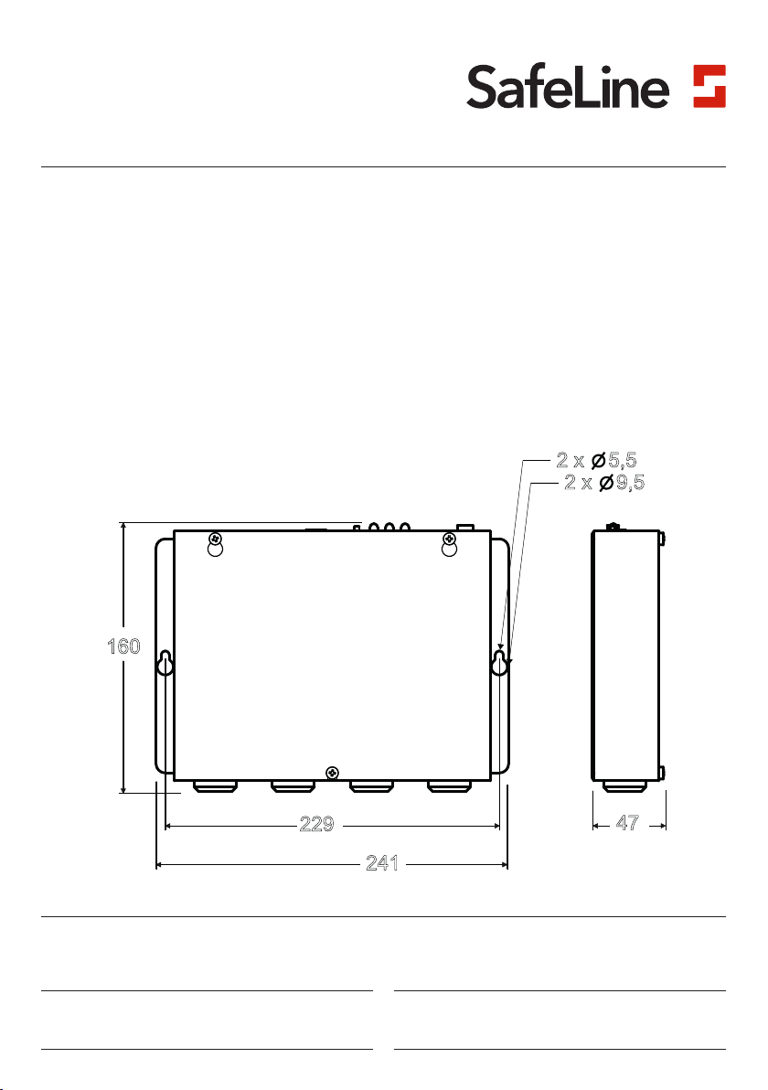
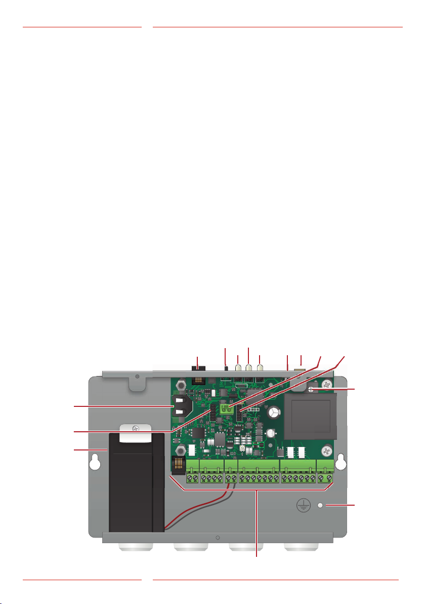
General
Information

4EN SL6+ v.3.04
Introduction
-It should not be modi ed or altered in any way, and should
only be installed and con gured strictly following the
procedures described in this manual.
- All applicable health and safety requirements and equipment
standards should be considered and strictly adhered to when
installing and con guring this product.
- After installation and con guration this product and the
operation of the equipment should be fully tested to ensure
correct operation before the equipment is returned to normal
use.
Electrical and electronic products may contain materials,
parts and units that can be dangerous for the environment
and human health. Please inform yourself about the local rules
and disposal collection system for electrical and electronic
products. The correct disposal of your old product will help
to prevent negative consequences for the environment and
human health.

5EN SL6+ v.3.04
Introduction
SafeLine SL6+
Power Supply voltage: 12 VDC, current drain nominal 15 mA
Inputs 10-30 VDC, 5 mA, optically isolated
Pictogram outputs Max 100 mA, 24 VDC, transistor outputs, open collector
IP code COP: IP00
COP2, Surface- or ush mounted units: IP40
To reach safety level IP4X, suitable additional protection have to
be installed onsite.
Max cable length 0,22 mm2 cable: 100 m
0,75 mm2 cable: 250 m
Operating temperature
+5 C° — +40 C°
Air humidity 30% — 90% RH
Technical Data Voice Unit
Power Supply voltage: 230 VAC min: 6,4 W, max: 9,4 W
Battery Battery voltage: 12 VDC lead battery
Capacity: 1,2 Ah
Charge: 13,65 VDC, max. 200 mA
Emergency light Emergency light output: 12 VDC max 500 mA
Emergency signal Acoustic emergency signal output: 12 VDC max 200 mA
Inputs 10-30 VDC, 5 mA, optically isolated
Antenna connector SMA (female)
Size SL6+: 241 x 160 x 47 mm (L x W x H)
SL6+ Mini: 244 x 113 x 52 mm (L x W x H)
Weight 1.7 kg
Relay outputs Max 1 A/30 VDC. volt free relay outputs.
IP code IP20
Soundles 16 sec/le
Bluetooth Bluetooth 4.0
BLE 2,4 GHz
Operating temperature +5 C° — +40 C°
Air humidity 30% — 90% RH
Interface Boards *SL6-GSM-BOARD:
- Micro SIM, 15 x 12 x 0,76 mm
- Supports 2G
- Requires SW 3.40 or later
*IF-BOARD-4G
- Micro SIM, 15 x 12 x 0,76 mm
- Supports 2G, 3G and 4G
- Requires SW 4.45 or later
Technical Data Main Unit

6
0
1
23
4
5
6
7
8
9
0
1
23
4
5
6
7
8
9
0
1
23
4
5
6
7
8
9
0
1
23
4
5
6
7
8
9
0
1
23
4
5
6
7
8
9
0
1
23
4
5
6
7
8
9
SafeLine Pro
SafeLine
Pro
EN SL6+ v.3.04
Overview
System
Overview
The SL6+ uses a bus system for communication between the
main unit (SL6+) and the voice units.
The bus consists of four wires, which transfers power, voice and
data.
You can have one SL6+ main unit and up to six voice units
connected to the same bus.
The system uses addresses to communicate with a selected
voice unit. It is important that each unit have the address selec-
tor set to a unique address. Available addresses are 1 to 6.
The system is based on a two-way system according to
EN81-28.
Description of
the Bus System
Intercom and
con guration
handset
Con gfuration and
software update
BUS
GSM LED
PSTN
USB RS232
System
Speaker
Aux. input 1
Aux. input 2
Emg.
bell
Emg.
button SW
update
External
pictogram Internal
Emg. light
Emg./Push to
talk button
Emg.
light
Address
selector Address
selector
Address
selector
Address
selector
Address
selector Address
selector
CAR UNIT CAR TOP LIFT PIT FIRE UNIT FIRE UNIT FIRE UNIT
SW update
Emg./Push to
talk button
SW update
Push to talk
button
SW update
Push to talk
button
SW update
Push to talk
button
SW update

7
44553
1000
6E
44553
1000
6E
2
3a
3b
3c 4
12
6
8
1 5
10
7
9
13
11
EN SL6+ v.3.04
Overview
1. Connector RJ12 for
optional telephone
handset
For con guration and
intercom communication
Can also be used for
external calls. Any
standard analogue tone
dial telephone can be
used.
2. Resets button
• Reset all alarms.
• Terminates a phone
call in progress.
• Triggers self test.
• Activates display of
GSM signal strength.
• Triggers battery test.
3. LED indicators
a. Mains power
b. Active alarm/battery
status
c. PSTN/GSM Net, call
status
4. USB Mini B PC connec-
tion
For rmware update and
con guration.
5. RS232 PC connection
For con guration.
6. Screw terminal for
optional telephone
handset
For con guration and
intercom communication.
Can also be used for
external calls.
Any standard analogue
tone dial telephone can
be used.
7. Slot for optional card
CANopen Lift
(*SL6-CAN-BOARD)
8. Connector for external
system speaker
9. GND
10. Terminals
11. 12 V Battery, 1,2 Ah
12. Slot for GSM interface
board
13. Battery slot for RTC, Real
Time Clock
(not yet implemented)
Overview SL6+
Main Unit

8
ADDRESS
J2
LOCAL BUTTON
BUS A
BUS B
OUT A (YELL.)
OUT B (GREEN)
INPUT A
INPUT B
EMG LIGHT +
HEARING LOOP
BUS GND
BUS 12V
J4 J3
-
RS2
5 7
44553
1000
6E
44553
1000
6E
44553
1000
6E
44553
1000
6E
BUS-STATION
WWW.SAFELINE.SE
K1
K2
K3
K4
K5
K6
K7
K8
K9
K10
P6
P4
P5
P2
P3
P7
6
9 10 11
21 3 4
8
EN SL6+ v.3.04
Installation
1. Local button*
Only N/O.
Is connected with *Cable13.
2. Screw connector terminals*
3. Emergency light*
Is connected with *Cable13.
4. Hearing loop*
Is connected with *Cable13.
5. RS232 PC connection
For rmware update.
6. Terminal RJ45
Input/output, bus connec-
tion, power and external
pictogram.
7. Address selector
Selects the bus address for
the unit.
8. Volume control
9. Pictogram yellow
10. Microphone
11. Pictogram green
* Note: This connection
may not be present
depending on the nature
of your product.
If the default address settings
needs to be changed it
can be done in the main unit
using SafeLine Pro
Overview SL6+
Voice Unit
Address Unit
1 Car unit
2 Top unit
3 Lift pit unit
4 Fire unit
5 Fire unit
6 Fire unit
Default address setting:

9
1
6
ADDRESS: 1
VOLUME
sw version
serial number
2
7
3 4 5
8
EN SL6+ v.3.04
Installation
1. Address selector
Fixed value set to 1 (car unit).
2. Connections
3. Pictogram output
4. Additional alarm button, N/O
5. RS232 PC connection
6. Volume control
7. Emergency light, only for SLB-SM-Pic-Light
8. Hearing loop
Overview SL6+
Voice Unit

10
3
4
5
12
43254
100
35V
43254
100
35V
63432
1000
6F
63432
1000
6F
SIM Card
73274
1000
6F
73274
1000
6F
100
35V
100
35V
TP5 TP11 TP9 TP3 TP12
TP7 TP4 TP6 TP8 TP10 TP1
SIM Card
EN SL6+ v.3.04
Installation
1. GSM
Circuit board with GSM antenna connector, SMA:
*SL6-GSM-BOARD or *IF-BOARD-4G (please refer to tech-
nical data, page 2, for detailed information).
2. SafeLine voice station for lif t pit/car top
Mounted in the lift shaft, on top or under the car.
3. GSM antenna
4. SafeLine voice station for car
Equipped with a speaker and a microphone. Voice units
available with pictograms to comply with EN 81-28. Also
available with emergency alarm button and Rec Fire Key
(key switch for re intercom.)
5. SafeLine voice station with emergency light, for car
Equipped with a speaker, a microphone and a built in
emergency light in the frame. Voice units available with
pictograms to comply with EN 81-28.
Other
Components

11
44553
1000
6E
44553
1000
6E
73274
1000
6F
73274
1000
6F
100
35V
100
35V
TP5 TP11 TP9 TP3 TP12
TP7 TP4 TP6 TP8 TP10 TP1
SIM Card
43254
100
35V
43254
100
35V
63432
1000
6F
63432
1000
6F
SIM Card
SafeLine SL6
>> 1,5 m >> 1,5 m
>> 1,5 m
EN SL6+ v.3.04
Installation
If GSM interface is installed
it has priority. If no active
SIM card is used, GSM
interface should be
disabled.
Mounting Install the main unit in the machine room.
No termination resistance is needed at the ends of the bus.
To avoid GSM interference: Place the main unit, the stations
and the GSM antenna at least 1,5 meters apart.
Mounting circuit board
Unplug the main power and battery before performing any
changes.
Circuit boards that can be mounted are *SL6-GSM-BOARD
or *IF-BOARD-4G (please refer to technical data, page 2, for
detailed information).
*SL6-GSM-BOARD
with Micro SIM Card
*IF-BOARD-4G
with Micro SIM Card

12
1
2
1
2
3
4
1
2
3
4
5
6
7
1
2
3
4
5
6
1
2
1
2
A
B
C
D
E
F
EN SL6+ v.3.04
Installation
Wiring Diagram
SL6+ Main Unit
INPUT 1 AND 2 OPTIONS
NONE
FILTER
LMS/SMS
CLEAR/MAINTENANCE
FIRE MODE
(default input 2)
ALARM BUTTON
(default input 1)
CALL DELAY
* Input 1 and 2 are congurable N/O or N/C inputs with
SafeLine Pro as indicated to the right.
** Maximum 200 mA on the emergency bell output.
*** Maximum 500 mA on the emergency light output.
Phone line, RJ12
Relay 1 Common
Relay 1 N/C
Relay 1 N/O
Phone line
Phone line
Bus 12 VDC
Bus GND
Bus A
Bus B
Battery +12 VDC
Battery 0 VDC
+12 VDC
Input 2*
(congurable)
Input 1*
(congurable)
Emerg. bell + **
Emerg. bell – **
Emerg. light + ***
230 VAC L
230 VAC N
Emerg. light – ***
Relay 2 Common
Relay 2 N/C
Relay 2 N/O

13
ADDRESS: 1
serial number
44553
1000
6E
44553
44553
44553
44553
44553
44553
44553
1000
1000
6E
44553
1000
6E
44553
1000
6E
B
EN SL6+ v.3.04
Installation
Wiring Diagram
Voice Unit
*Input A is con gurable with either:
• SafeLine Pro N/O (default) or N/C.
• Parameter *89*, please refer to the corresponding
code in the ”Parameter List”.
Grey
Orange
Black
Red
Yellow
Green
Blue
Brown
Input B, not in use
Input A, alarm button (optional)
Output A, yellow pict. (optional)
Output B, green pict. (optional)
B2 bus GND
B1 bus 12 VDC
B4 bus B
B3 bus A
ONLY WHEN USING
EXTERNAL PICTOGRAM AND ALARM BUTTON
JST connection
*Cable18
RJ45 connection
*Cable03

14
8
7
6
5
4
3
2
1
44553
1000
44553
1000
44553
1000
6E
44553
1000
6E
44553
1000
6E
44553
1000
6E
44553
1000
6E
44553
1000
6E
44553
1000
6E
44553
1000
6E
44553
1000
6E
44553
1000
6E
44553
1000
6E
44553
1000
6E
COPYRIGHT SAFELINE AB 2011
WWW.SAFELINE.SE
SL6 R1.12
SPEAKER
44553
1000
6E
44553
1000
6E
44553
1000
6E
44553
1000
6E
44553
1000
6E
44553
1000
6E
44553
1000
6E
44553
1000
6E
44553
1000
6E
44553
1000
6E
COPYRIGHT SAFELINE AB 2011
WWW.SAFELINE.SE
SL6 R1.12
SPEAKER
44553
1000
44553
1000
44553
1000
6E
44553
1000
6E
44553
1000
6E
44553
1000
6E
44553
1000
6E
44553
1000
6E
44553
1000
6E
44553
1000
6E
44553
1000
6E
44553
1000
6E
44553
1000
6E
44553
1000
6E
COPYRIGHT SAFELINE AB 2011
WWW.SAFELINE.SE
SL6 R1.12
SPEAKER
44553
1000
6E
A A A
EN SL6+ v.3.04
Installation
Wiring Diagram
Voice Unit Screw
Terminals
*Input A is con gurable with either:
• SafeLine Pro N/O (default) or N/C.
• Parameter *89*, please refer to the corresponding
code in the ”Parameter List”.
Connecting the
Telephone Line
Connect the telephone line in parallell in universal
terminals or the RJ-plug, see the picture above.
It’s possible to connect up to nine SL6+ main units to the
same telephone line.
In order to access the unit remotely, it needs to be
assigned a unit number. Please refer to parameter *82* in
the “Parameter List” for more information.
Phone line is connected via RJ12 through the following:
RJ12
1
2
3
4
5
6
Input
Not in use
Output
Output
Not in use
Input
7. Bus GND
8. Bus 12 VDC
6. Not in use
5. Input A*, alarm button
4. Output B, green
pictogram
3. Output A, yellow pictogram
1. Bus A
2. Bus B

15
TP5
EN SL6+ v.3.04
Installation
The SL6+ can only recognise the PIN code if the code is
set to “1234”, “0000”, “1111” or is deactivated. If the PIN
code is set to “1234”, “0000” or if it is deactivated, the SIM
card can be moved from the SL6+ to any of SafeLine GSM
products.
TIP: Do not activate the voice mail or, if possible, ask your
provider to deactivate the voice mail.
If the PIN code is set to “1111” the SIM card code will
be randomly changed by the SafeLine GSM unit and
memorized. This way the SIM card can only work with
the SafeLine GSM unit unless you use the PUK code for
setting up a new PIN code.
If you want to upload a new SIM card with PIN code “1111”
you will rst need to upload a SIM card with PIN code
“1234” or “0000” to clear the old code in memory.
Setting the PIN code
(Set to “1234”, “0000” or deactivate.)
1. Insert the SIM card in an ordinary cellular phone. In
the “Security settings” menu, change the PIN code to
“1234”. If this is not possible, set the PIN code to “0000”
or set the ”PIN code request” option to “OFF” (might
not always function).
2. Verify the PIN code by switching your phone off and
on again.
3. Make a call from your phone to verify that the SIM card
is active before you move it to the SL6+.
4. Also make a call to SL6+ after insertion to check that it
is possible to get a proper connection.
Activating the
SIM Card
If you enter the wrong PIN
code 3 times, the SIM card
will be blocked (requires
PUK code to unblock). The
SL6+ can not be started and
the LED3 will turn red.

16
44553
1000
6E
44553
1000
6E
44553
1000
6E
44553
1000
6E
44553
1000
6E
44553
1000
6E
44553
1000
6E
44553
1000
6E
44553
1000
44553
1000
44553
1000
6E
6E
6E
6E
6E
44553
1000
6E
44553
1000
6E
COPYRIGHT SAFELINE AB 2011
WWW.SAFELINE.SE
SL6 R1.12
EN SL6+ v.3.04
Startup
LED 1
LED 2
LED 3
Reset
COLOUR CODE LED
1 2 3
GSM SIGNAL
STRENGTH
3 green = 100 %
1 yellow, 2 green = 85 %
2 yellow, 1 green = 70 %
3 yellow = 55 %
1 red, 2 yellow* = 30 %
2 red, 1 yellow = 15 %
3 red = 0 %
*Minimum signal strength for using GSM interface.
LED Indication
Front Panel
Continuous green Mains power supply OK
Flashing red (400/400 ms) Battery operated, with power to the emergency light.
Continuous red Battery operated, no power to the emergency light.
LED 1 indicates the power supply status
Light off No ac tive alarm/batter y OK.
Rapidly ashing yellow Active alarm not reset.
(200/200 ms)
Flashing red (400/400 ms) Battery check in progress.
Continuous red Batter y test failure/no battery connected.
LED 2 indicates active alarm and battery condition
Flashing green (100/100 ms) Fire mode activated.
Flashing green (400/400 ms) Call connection in progress.
Slowly ashing green Telephone line connected.
(200/4600 ms) GSM network OK.
Continuous green Call connected.
Flashing yellow (100/100 ms) Incoming call.
Flashing red (400/400 ms) No telephone line connected.
Searching for GSM network.
Continuous red No SIM card (when using GSM).
LED 3 indicates the phone line's status
Press for 3 sec Show GSM signal strength (see table below).
Press 3 times Start a self test (battery + bus initialization).
Press once Resets an active alarm. Aborts calls in progress.
Press 5 sec - release SL6+ turns off. NOTE! Refers to battery powered only!
Reset button

17 EN SL6+ v.3.04
Startup
LED Indication
for Pictogram in
Car
Yellow LED Green LED
Call in progress
The yellow pictogram LED,
is lit as soon as the alarm
button is pressed.
Call connected
The green pictogram LED
turns on as soon as the
SafeLine unit detects a
responding voice.
The LED is turned off when
the call is terminated.
Standard (*78*0#) Yellow LED Green LED
Light off No alarm activated Telephone line not OK.
Flashing slowly Flashing once ever y 5
seconds
Telephone line not OK.
Flashing once ever y 5
seconds
Unit is OK.
Flashing quickly Flashing twice every
second
Alarm button active.
Flashing two times every 5
seconds
Alarm lter activated.
Continuous light Activated alarm. Remains lit
until reset. Call connected.
Strictly EN81-28 (*78*1#) Yellow LED Green LED
Flashing Flashing twice every
second
Alarm button active.
Continuous light Activated alarm. Remains lit
until reset. Call connected.

18
123456
1
2
3
4
5
6
7
1
2
4
6
3
5
7
EN SL6+ v.3.04
Startup
The unit will not start
at battery connection
only.
A tone sequence is
heard in the system
speaker at startup.
Check 230 VAC mains
power.
SL6+ main unit searches
for units connected to
the bus. For every voice
unit found, a beep
sound is heard in the
system speaker in the
SL6+ main unit.
Refer to chapter:
Trouble shooting Voice
unit.
When a valid telephone
line is connected, or
a GSM net is available
LED3 is ashing green
every 5 seconds.
Refer to chapter: Trou-
ble shooting Main unit.
Example:
Found all voice units
except for number 3.
Startup
Procedure
Connect 230 VAC.
LED 1
turns green?
Number of beeps
OK?
LED 3 ashing
OK?
Unit communication
failure.
Connect the battery.
Startup procedure
ready.
No
Yes
Startup the SL6+.
SL6+ checks for valid tele-
phone line or GSM net.
SL6+ searches for
connected bus units.
No telephone
line or GSM net.
No 230 VAC
or broken unit.
Yes
Yes
No
No

19 EN SL6+ v.3.04
Conguration
App Store, iPhone Google play, Android
CONNECT CONNECT is the tool from SafeLine that will make
con guration of SafeLine products easier than ever before.
Con guration is done wirelessly with compatible produc ts and
the SafeLine CONNECT smartphone app, which is available
free of charge on the Apple App Store and on Google Play.
Easy to learn and use
The app has an intuitive interface for con guration and
changes of settings. Simply follow the instructional steps in the
app to con gure the SafeLine unit. There is no longer any need
to use a computer or to remember a long list of con guration
codes in order to con gure SafeLine produc ts. CONNECT
functions includes templates which will allow pre-con gured
settings.
CONNECT is secure
CONNECT is protected against unauthorised use and all
SafeLine products with built-in CONNECT functionality are
password protected.
Always accessible
With the built-in CONNECT func tionality, con guration
is always accessible. All that is needed is a smartphone or
tablet with the free app installed – no computer needed for
con guration or changes in settings.
If the unit has been
operational for more than
10 minutes when trying
to connect, it will ask for a
password.
If that is the case: please
turn the unit off and on
again, then try to reconnect.

20
SafeLine Pro
SafeLine
Pro
SafeLine SL6
SafeLine SL6
SafeLine
ProLink
SafeLine Pro
SafeLine
Pro
EN SL6+ v.3.04
Con guration
Con guration with SafeLine Pro.
The unit can be con gured at the of ce prior to the installation
or on site af ter installation. The con guration software SafeLine
Pro can be downloaded from www.safeline-group.com.
The con guration cable is provided by SafeLine.
If SafeLine Pro is used for con guration, you can go directly to
chapter “Operating”.
Remote con guration with SafeLine Pro/ProLink.
The unit can also be remotely con gured at the of ce after
installation. Connect a SafeLine ProLink modem with a phone
line to a computer with SafeLine Pro and a serial cable.
Con guration
with PC
Other manuals for SL6+
3
Table of contents
Other Safeline Emergency Phone manuals
Popular Emergency Phone manuals by other brands

Talkaphone
Talkaphone ETP-MT installation instructions

Talkaphone
Talkaphone VOIP-500 Series installation guide

AT&T
AT&T SPAREONE user guide

Linear
Linear Personal Emergency Reporting System... Installation & operating instructions

Merak
Merak MEP2L manual

My Alert Center
My Alert Center MyIndependance quick guide