SAFEMATIC MLP Series User manual

MULTILUBE
MLP
HMLU2CEN.doc 21.03.2006 Rev. 2C
PUMPING UNIT MLP
TABLE OF CONTENTS
1 GENERAL DESCRIPTION................................................................................................................................1
2 DESIGN.............................................................................................................................................................1
3 OPERATION......................................................................................................................................................1
3.1 Filling the lubricant reservoir of the pumping unit.......................................................................................2
4 TECHNICAL SPECIFICATION..........................................................................................................................3
4.1 Technical specifications..............................................................................................................................3
4.2 Electrical safety...........................................................................................................................................3
4.3 Electromagnetic Compatibility (EMC) for 115 V AC ...................................................................................3
4.4 Connections................................................................................................................................................4
4.5 Symbols ......................................................................................................................................................5
5 SPARE PARTS..................................................................................................................................................5
4 APPENDICES

MULTILUBE
MLP
HMLU2CEN.doc 21.03.2006 Rev. 2C
1 (5)
PUMPING UNIT MLP
1 GENERAL DESCRIPTION
The pumping unit is designed for pumping lubricant into central lubrication system.
2 DESIGN
Note Numbers in brackets are part numbers of drawing 461790A.
Pumping unit comprises of a body (pos.1) and a lubricant reservoir (pos.2).
The body comprises of a pump element (pos.3), an electric motor (pos.4), a line valve (pos.5),
a pressure relief valve (pos.6), a heating element (pos.7) and a power supply (pos.8). Pumping
unit is controlled by a user interface (pos.9) and a circuit board (pos.10). If external control is
used, user interface and circuit board are replaced with relays (pos.11). Pumping unit is
equipped with a pressure sensor (pos.12) for each line which can be replaced with an external
pressure control unit.
Lubricant reservoir is equipped with a follower piston (pos.13), a level indicator (pos.14) and a
low level switch (pos.15). Filling connector (pos.16) of the lubricant reservoir is equipped with a
filter (pos.17) and a safety valve (pos.18).
Pumping unit is equipped with a supporting block (pos. 19).
3 OPERATION
When pressurization begins, the control starts the pump and opens the line valve. In pressure
sensor and pressure transmitter operation the pump stops when pressure exceeds the set high
limit and starts, when the pressure goes below the set high limit. In pressure switch operation
the pump stops, when the pressure switch closes and restarts, when the pressure switch
opens. After the set pressurization time, the control stops the pump and pressure discharges
from the line to the lubricant reservoir.
If the lubricant level in the reservoir drops to the low limit level during pumping, the reservoir
low level switch sends an alarm to the control and pumping is stopped. The alarm can be
disabled by filling the lubricant reservoir and resetting the alarm.
Caution The viscosity of used oil must be min. 46 cSt in pumping unit operation
temperature.
Caution Check valve EOS-CV must be used in an oil lubrication system. The check
valve prevents the piping from draining during interval. See drawing
462119.

MULTILUBE
MLP
HMLU2CEN.doc 21.03.2006 Rev. 2C
2 (5)
3.1 Filling the lubricant reservoir of the pumping unit
Lubricant reservoir of the pumping unit is filled through the filling connector which is equipped
with a filter.
Use of filling device (Safematic code 11600352; suitable for 20 l / 18 kg barrel)
Note Numbers in brackets are part numbers of drawing 461799A.
1. Ensure that the surroundings of the pumping unit are clean. Impurities in the system
prevent trouble-free operation and cause damage when reaching the lubrication point.
2. Remove the lid from the lubricant reservoir (1) and press the follower plate (2) tightly to the
reservoir above the lubricant. Follower plate is not used with fluid lubricants, as it does not
remain on the surface.
3. Place the lid (3) on top of the lubricant reservoir. Fasten the lid with wing screws (4) on the
lubricant reservoir.
4. Place the pump (5) through the lid into the follower plate central unit (6).
5. Connect the lubricant hose (7) to the pump.
6. Fill the lubricant hose by pumping by hand.
7. Connect the quick connector (8) to the lubricant hose.
8. Connect the quick connector to the pumping unit filling connector (9).
9. Fill the lubricant reservoir of the pumping unit by pumping slowly by hand.
10. Filling of the lubricant reservoir can be followed at the level indicator (10). To prevent
overfilling, the pumping unit is equipped with a safety valve (11).
11. Turn the pump handle (12) to upright position so that pressure discharges to the lubricant
reservoir.
12. Disconnect the quick connector from the pumping unit filling connector.
13. Fasten the protecting cap (13) of the pumping unit filling connector.
14. Fasten the protecting cap (14) of the filling device quick connector.
Caution Do not fill the reservoir without the filter.
Caution Filter (15) of the filling connector has to be cleaned regularly and replaced if
necessary. Cleaning and replacing has to be performed when the reservoir
is empty.

MULTILUBE
MLP
HMLU2CEN.doc 21.03.2006 Rev. 2C
3 (5)
4 TECHNICAL SPECIFICATION
4.1 Technical specifications
Quantity Range Unit Description
t -30…+70 °C Operation temperature
pmax 250 bar Maximum pressure
U 24 DC, 115 AC or
230 AC V Control voltage
U 24 DC, 115 AC or
230 AC V Power input
P 150 W Power consumption
13 g/min Pump capacity
V 4 or 10 l Reservoir volume
m 20
28 kg Weight, full 4 l reservoir
Weight, full 10 l reservoir
Aluminium Body material
273 x 538 x 246
273 x 720 x 246
(w x h x d)
mm Dimensions, 4 l reservoir
Dimensions, 10 l reservoir
IP65 Protection classification
4.2 Electrical safety
Note Check supply voltage from the pump name plate (115 or 230 V AC). Pump
is equipped with a 3 m power cord for connecting to the electrical network.
Connection to the network is made next to the pump with a plug or by using
a connection box equipped with a 2-pole switch (for example Safematic
code 10543062).
4.3 Electromagnetic Compatibility (EMC) for 115 V AC
The equipment complies with following requirements:
FCC CFR 47 Part 15
(July 2003) Subpart B Class B
Note This device complies with Part 15 of the FCC Rules. Operation is subject to
the following two conditions:
(1) this device may not cause harmful interference, and
(2) this device must accept any interference received, including
interference that may cause undesired operation
Note Changes or modifications not expressly approved by the party responsible
for compliance could void the user’s authority to operate the equipment.

MULTILUBE
MLP
HMLU2CEN.doc 21.03.2006 Rev. 2C
4 (5)
Note This equipment has been tested and found to comply with the limits for
Class B digital device, pursuant to Part 15 of the FCC Rules. These limits
are designed to provide reasonable protection against harmful interference
in residential installation. This equipment generates, uses and can radiate
radio frequency energy and, if not installed and used in accordance with the
instruction manual, may cause harmful interference to radio
communications. However, there is no guarantee that interference will not
occur in a particular installation. If this device does cause harmful
interference to radio or television reception, which can be determined by
turning the equipment off and on, the user is encouraged to try to correct
the interference by one or more of the following measures:
- reorient or relocate the receiving antenna
- increase the separation between the equipment and receiver
- connect the equipment into an outlet on a circuit different from that to
which the receiver is connected
- Consult the dealer or an experienced radio/TV technician for help.
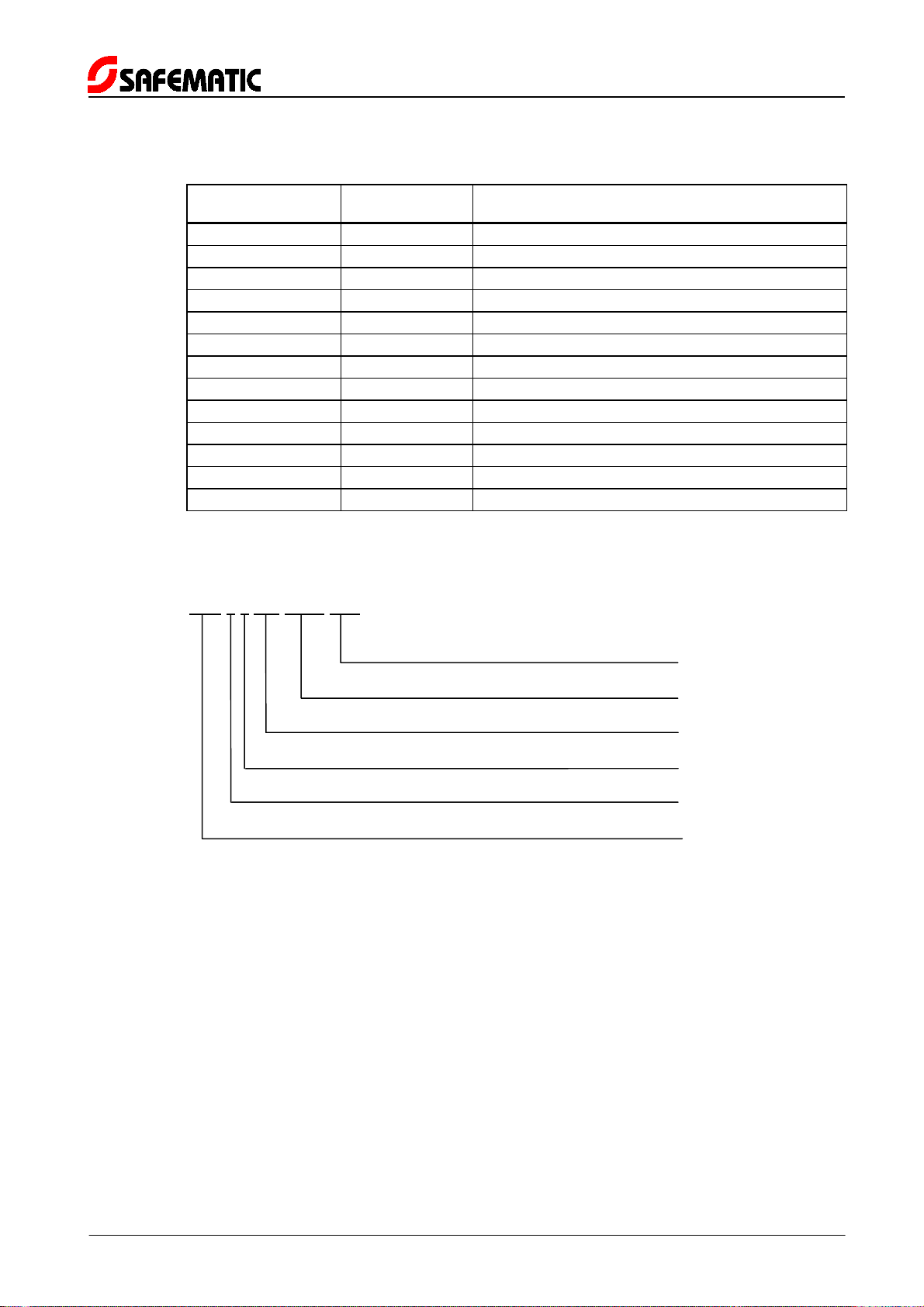
4.4 Connections
Input
•pressure switch, 2 pcs, closing contact
or pressure transmitter, 2 pcs, 4–20 mA / 0–250 bar, 2-wire type
•interlocking, lubrication points in operation when external interlocking switch is open
Output
•lubricant, 2 pcs, female thread R ¼”
•alarm, potential-free contact open in alarm mode, load 115V / 1A max.
Cable channels in the intermediate plate
•PG 13,5 cable gland, 2 pcs, for 6-12 mm cable diameters
•PG 11 cable gland, 2 pcs, for 4-10 mm cable diameters

MULTILUBE
MLP
HMLU2CEN.doc 21.03.2006 Rev. 2C
5 (5)
4.5 Symbols
MLP-A-B-C-D-E Abbreviation Description
MLP: MLP MultiLube pump
A: 4 Lubricant reservoir volume, 4 l
10 Lubricant reservoir volume, 10 l
B: 1 Number of lines, 1-line system
2 Number of lines, 2-line system
C: 24 Power input, 24 V
115 Power input, 115 V
230 Power input, 230 V
D: IF103 User interface, IF-103
24 External control unit, control voltage 24 V DC
115 External control unit, control voltage 115 V AC
E: PSE Pressure control unit, built-in pressure sensor
no symbol Pressure control unit, external pressure control unit
Example:
MLP-4-2-230-IF103-PSE
Power input, 230 V
User interface, IF-103
Pressure control unit, built-in pressure sensor
Number of lines, 2-line system
Lubricant reservoir volume, 4 l
MultiLube pump
5 SPARE PARTS
See MLP-pumping unit spare parts (drawing no. 361033G).


This manual suits for next models
1
Table of contents
Other SAFEMATIC Lubrication System manuals