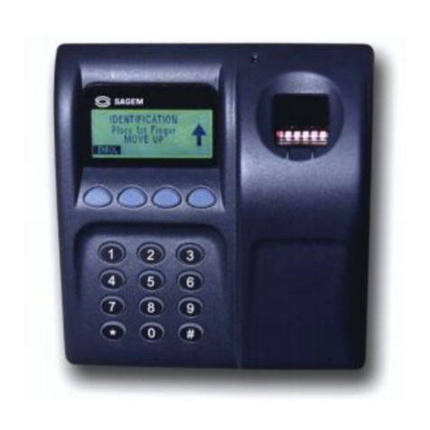
Sagem MorphoAccess 200E User manual


i

i
CONTENTS
Welcome to SAGEM SA MorphoAccess™ 1
Safety instructions 2
General description 4
Installation instructions 6
Pre-Installation Checklist for the MorphoAccess 6
Initial Installation Procedure 7
Stage 1: Preparing the MorphoAccess cables/wires for installation 7
Stage 2: Positioning and preparing the MorphoAccess for nal installation
against the mounting surface 8
Final installation procedure 10
Stage 1: Wiring the MorphoAccess to the building 10
Stage 2. Fastening the MorphoAccess to the building 11
Stage 3. Installing the MorphoAccess protective visor 12
Stage 4: Testing the MorphoAccess functionality 12
How to upgrade MorphoAccess 200E to 300E 14
Pre-Installation checklist 14
Performing the upgrade 14
Conguring Wiegand vs. Data clock 17
Performing the Conguration 17
Outdoor MorphoAccess Technical characteristics 20
Recommendations 22
Areas containing combustibles 22
General precautions 22
Appendix 1 - Cable conguration tables 23
Appendix 2 - Wall fastener specs 26
Product Warranty, Limitations and Software License 27
Contents

ii 1

ii 1
Welcome to SAGEM SA MorphoAccess™ 200E / 300E
Congratulations for choosing the SAGEM SA MorphoAccess™
Automatic Fingerprint Recognition Terminal. The MorphoAccess
provides an innovative and effective solution for access control
or time and attendance applications using ngerprint verication
and/or identication.
The MorphoAccess terminal integrates SAGEM image
processing and feature matching algorithms (MorphoSoft™
and MorphoImaging™). This technology is based on lessons
learned during 18 years of experience in the eld of biometric
identication and the creation of literally millions of individual
ngerprint identication records.
We believe you will nd the SAGEM SA MorphoAccess fast,
accurate, easy to use, and suitable for physical access control
or time and attendance.
The SAGEM SA MorphoAccess offers the following
advantages:
- Has been designed for use in outdoor environments, is
protected against water jets and is dust tight
- Has a high quality optical scanner
- Supports multiple input/output interfaces used in the physical
access control industry
- Has a local area network interface for easy interaction with
other host systems
- Is easily installed and integrated into your available ofce
space
- Has an interface that is easy to use in both setup and
operational modes
- Has extensive, exible ash memory for data storage (user
data, biometric templates, etc.)
To ensure proper installation of your SAGEM SA MorphoAccess,
we recommend that you read this Installation Guide in its
entirety.
Introduction
The SAGEM logo and trademark are the property of E.
All other trademarks or product names are trademarks or product names of the respective title
holders.

2 3
Safety instructions - Please Read Before Installation
WARNING: INSTALLATION TO BE PERFORMED BY
PROFESSIONAL INSTALLERS ONLY
Note: These instructions for the installation of the MorphoAccess
assume the installer is properly qualied as a professional,
familiar with applicable industry standards, local building/zoning
codes, and proper installation practices. Installation should not
be attempted by non-professionals.
You are required to use a National Electric Code Class 2 power
supply at 12 V DC ± 5% and 2.5A minimum. This product is
intended to be installed in accordance with the NEC Class 2 r
equirements.
Europe: SAGEM SA hereby declares that the SAGEM SA
MorphoAccess™ has been tested and found compliant with
the below listed standards as required by the EMC Directive
89/336/EEC: EN55022 (1994) / EN55024 (1998) and by the low
voltage Directive 73/23/EEC amended by 93/68/EEC: EN60950
(2000).
USA: This device complies with part 15 of the FCC Rules.
Operation is subject to the following two conditions: (1) this
device may not cause harmful interference, and (2) this device
must accept any interference received, including interference
that may cause undesired operation.
If this equipment interferes with radio or television reception
(which can be determined by disconnecting and re-connecting
the unit), the user is encouraged to try to correct the interference
by one or more of the following measures:
- Reorient or relocate the receiving antenna.
- Increase the separation between the equipment and
receiver.
- Connect the equipment into an outlet on a circuit different
from that to which the receiver is connected.
- Consult the dealer for help.
Safety instructions

2 3
CAUTION
RISK OF EXPLOSION IF BATTERY IS REPLACED BY AN
INCORRECT TYPE.
REPLACE ONLY WITH THE SAME OR EQUIVALENT TYPE
RECOMMENDED BY THE MANUFACTURER.
MUST BE DISPOSED OF PROPERLY.
Safety instructions
ATTENTION
IL Y A DANGER D'EXPLOSION S'IL Y A REMPLACEMENT
INCORRECT DE LA BATTERIE.
REMPLACER UNIQUEMENT AVEC UNE BATTERIE DU
MÊME TYPE OU D'UN TYPE ÉQUIVALENT RECOMMANDÉ
PAR LE CONSTRUCTEUR.
ELIMINER DE FAÇON APPROPRIÉE.
WARNING: Failure to properly seal the MorphoAccess against the mounting
surface may result in accident or injury. Due to the many types of building
materials that exist, ensuring adequate sealing against the mounting surface
is the sole responsibility of the installer. The mounting gasket provided with
the MorphoAccess is only for the convenience of the installer. For some
applications with rough mounting surfaces, a bead of silicone sealant can
be placed around the entire perimeter of the gasket before placing the
MorphoAccess against the mounting surface.
WARNING: As an additional precaution, take all steps necessary (in
accordance with the National Electric Code) to ensure that if water leaks into
the mounting surface, that no high voltage or other potentially dangerous
wiring, power sources, transformers, or electronics will become wet. This
may include installing high voltage wiring or electronics above the hole
in which MorphoAccess is mounted and waterproong connections as
needed. Providing for safety outside the MorphoAccess packaging is the
sole responsibility of the installer.

4 5
General description
3D View
Display
136 x 34 pixels
Keyboard
Sensor
Mounting slots
(4 places)
Front View
Function keys
Visor
General description

4 5General description
Rear View
Wiegand
RS-485
Power
Ethernet
Multi-function
Wall Gasket
Location

6 7Pre-installation checklist
Installation instructions
The installation instructions are divided into three segments -
The Pre-Installation Checklist, The Initial Installation Procedure,
and the Final Installation Procedure. Each segment lists the
procedures you will perform, followed by the detailed instructions
for each procedure.
Pre-Installation Checklist
1. Installation should be performed by a trained and qualied
installer. Make sure to adhere to all applicable local building
codes. A National Electric Code (NEC) Class 2 power supply
must be used for the MorphoAccess.
2. Prepare for the MorphoAccess installation by selecting a
mounting location that reduces exposure to the environment
as much as possible within easy reach of the door that is
being controlled by the MorphoAccess.
3. Verify that a standard junction box, at least the size of a
dual-gang box, has been installed at the correct height
necessary for the MorphoAccess to meet any local or Federal
requirements for ADA compliance.
4. Verify that there is enough free wall space surrounding
the junction box to accommodate the placement of the
MorphoAccess.
5. Verify that the main power and functional interface cables are
properly wired within the building, per applicable local building
codes, and that wire stubs are accessible within the junction
box where the MorphoAccess will be installed.
6. Turn off the main power to the junction box until the installation
of the MorphoAccess is complete.
Note: Once steps 1 through 6 are complete, the
MorphoAccess is ready for installation.

6 7
Initial Installation Procedure
The Initial Installation Procedure consists of two stages: (1) Preparing the
MorphoAccess cables/wires for installation, and (2) Positioning and preparing
the MorphoAccess for nal installation against the mounting surface.
Stage 1: Preparing the MorphoAccess cables/wires for
installation
1. Identify the MorphoAccess cables that will be wired for your
particular installation requirements, for example, power,
Wiegand, or RS-485.
Note: The Ethernet cable comes prewired for 568B with a
standard RJ45 socket installed. The interface cables have
a protective cover placed over the end of each cable. If
the interface cables are used for an installation, remove
the protective cover in order to perform the necessary
wiring.
2. Familiarize yourself with the cable wire diagrams located in
Appendix 1 of this installation guide.
3. Prepare the MorphoAccess cables for connection to the
building cables as follows:
a. Shorten the MorphoAccess cable stubs as necessary for
each installation.
b. Strip one inch of the cable insulation from the end of each
cable you will be using.
Note: Be careful not to cut the individual wires within
the cables.
c. Strip - inch of insulation from the end of each individual
wire you will be connecting.
Note: If you are using self-tapping wire connectors, this
step may not be necessary.
4. Prepare the building cables for installation in the same manner
as described above for the MorphoAccess cables.
Initial installation

8 9
Stage 2: Positioning and preparing the MorphoAccess for nal
installation against the mounting surface
1. If you haven't already done so, use the included hex wrench
to unscrew the four screws securing the MorphoAccess visor
and remove the visor. Place the visor out of the way until
needed at the end of the installation procedure.
2. Lift the MorphoAccess into position near the junction box
and place the wire stubs inside the junction box in order
to temporarily position the device against the mounting
surface.
3. Orient the MorphoAccess against the mounting surface in
the position that it will be permanently mounted with the
cable stub seals centered within the junction box without
any excessive stress applied to the cables.
4. Once you are satised with the location of the device against
the mounting surface, remove the backing from the gasket
material and position the sticky side of the gasket against
the backside of the MorphoAccess ensuring that the gasket
material does not cover the mounting holes.
5. Once the MorphoAccess is properly positioned against the
mounting surface, mark the location of the four fasteners at
the center of the four oval slots, cut out in the ange, that
surrounds the MorphoAccess. (See diagram on Page 5)
6. Once the four fastener locations are marked, remove the
MorphoAccess from against the mounting surface and place
in a safe location, out of the way from your work area.
7. Drill and prepare the holes for the four fasteners.
Note: The MorphoAccess comes with four Alligator™
anchors. These anchors can be used to mount the device
to any surface, of any thickness above 1/4" (6mm).
For complete technical specications for the Alligator
anchor please visit: http://www.toggler.com/pdf/
alligator.pdf
Positioning and preparing the MorphoAccess

8 9
For other types of surfaces you should select an appropriate
anchor that is rated to support a minimum of 5 lb (2.25 kg).
See Appendix 2, p. 26 for generic bolt specications.
Note: A variety of fasteners can be used to mount the
MorphoAccess to different types of material. The mounting
holes must be prepared according to the type of fastener
being used for an installation and the type of material
the MorphoAccess is being mounted against. Use "best
practices" installation procedures for the type of fastener
being used.
8. Once the fastener locations are properly prepared for accepting
the fasteners, temporarily mount the MorphoAccess to the
mounting surface to check for proper alignment of the
fasteners and placement.
9. To temporarily mount the MorphoAccess, lift the device into
position near the junction box and place the wire stubs inside
the junction box in order to position it against the mounting
surface.
10. Fasten the device to the mounting surface with the four
fasteners.
11. If you are satised with the mounting, remove the device
from the wall and place it in a safe location, away from your
work area. If you need to make an adjustment, remove the
MorphoAccess from the wall and make the adjustment
accordingly.
You are now ready for the nal installation procedure.
Positioning and preparing the MorphoAccess

10 11
Final Installation Procedure
The Final Installation Procedure includes four stages: (1) Wiring
MorphoAccess to the building, (2) Fastening MorphoAccess to
the building, (3) Installing the MorphoAccess protective visor,
and (4) Testing MorphoAccess functionality.
Stage 1: Wiring MorphoAccess to the building
1. Position MorphoAccess in such a way that the wire stubs are
conveniently placed within reach of the building wire stubs.
Note: To accomplish this may require placing the
MorphoAccess on a stool or other secure work surface in
order to position it at a height that allows the installer
to conveniently connect the wires to the building wires
without needing to physically hold the device in position.
2. Refer to the cable wire diagram provided in Appendix 1 of
this installation guide for the color coding of each individual
wire that will be connected for your installation.
Note: Wiring the MorphoAccess includes connecting the
interface wires rst, then connecting the power wires. Once
all wires have been properly connected and sealed against
the elements, MorphoAccess will be ready to be secured
to the mounting surface.
4. Connect each MorphoAccess wire to the corresponding wire
in the building cables. Take care when connecting the wires
in order not to damage the individual wires and to ensure a
positive connection. Each wire should be properly wrapped
or sealed in order to ensure uninterrupted service to the
device. Follow NEC installation requirements when wiring
this device.
FInal Installation

10 11
Stage 2. Fastening MorphoAccess to the building
1. To complete permanent mounting of the MorphoAccess,
neatly wind and place the cable harness inside the junction
box without any excessive stress applied to the harness.
This will facilitate the mounting of the device tight against the
mounting surface.
2. Once the wire harness is in place in the junction box, place the
device against the mounting surface and align the slots in the
ange with the holes in the mounting surface.
Note: The mounting holes should have been pre-drilled
and prepared for installation as outlined earlier in the Initial
Installation Procedure.
3. Once the device is properly placed against the mounting
surface, ensure that it makes a positive sealed connection
between the mounting surface and the gasket on the back
of the device.
Note: To ensure a watertight seal on rough mounting
surfaces, a bead of silicone sealant can be placed around the
entire perimeter of the gasket before placing MorphoAccess
against the mounting surface.
4. Install the four screws through the slots in the ange into the
four prepared mounting holes. Tighten the mounting screws.
Note: Be careful not to overtighten the screws or the front
housing will bend visibly under the bolt heads.
Note: If you use mounting screws that pass through the
mounting surface (such as a thin wall or an electrical
mounting box), be sure to seal the mounting screw holes
per the NEC for outdoor installations.
Final installation

12 13
Stage 3. Installing the MorphoAccess protective visor
Warning: The protective visor must be installed in order to
protect the nger imaging scanner and the LCD display from
direct sunlight and dripping water.
1. Place the protective visor over the MorphoAccess and align
the four mounting holes on the visor with the four mounting
holes on the ange.
2. Re-attach the visor to the ange with the included four screws
and washers using the included hex wrench. Firmly tighten
each screw to 8 in-lb (0.90 N-m).
3. Place the provided screw caps over each screw to complete
a nished look.
4. Remove the protective lm covering the LCD window.
Stage 4: Testing MorphoAccess functionality
1. Once the installation is complete, turn on the main power to
the MorphoAccess.
2. Inspect the MorphoAccess and verify that it powers up and
proceeds to the main screen.
3. Inspect the LCD and verify that the contrast and brightness
settings make the screen readable. If the LCD is not readable,
see the setup menu in the Software Guide for how to adjust
the contrast and brightness of the LCD screen.
4. Inspect the scanner and verify that the scanner is glowing
red.
5. Have the Administrator perform an enrollment and verify that
the enrollment is successful.
Note: This step depends on the type of system conguration
and may not be appropriate for all installations.
Final installation

12 13Final installation
6. Perform an identification and verify that the door opens
correctly.
Note: This step depends on the type of system
conguration and may not be appropriate or available for
all installations.
Note: If any unexplained problems occur, please contact
the company where you purchased the MorphoAccess for
troubleshooting instructions.
Installation of MorphoAccess is now complete.

14 15Upgrading
How to upgrade MorphoAccess™ 200E to 300E
Pre-Installation checklist
This is a memory upgrade which, when installed, provides the
capability to manage 16 biometric databases of 3,000 records
each for a total of 48,000 people.
Note: This memory upgrade must be performed by authorized
personnel only. Any work carried out by non-authorized
personnel will invalidate your warranty.
Warning: Make sure the existing database residing on the
MorphoAccess 200 has been backed up before continuing
with this upgrade.All existing database information in the
MorphoAccess 200 will be lost during this procedure. If
transferring a memory module from one MorphoAccess 300
to another, all database information contained on the module
will be lost.
Performing the upgrade
1. Remove the MorphoAccess visor screw caps, with a small
straight blade scewdriver, and then remove the four visor
screws, using the included hex wrench, and disconnect the
MorphoAccess from the mounting surface and make sure
the main power to the device is turned off.
2. Unscrew the front housing from the back housing by removing
the four screws securing the two halves together using the
included hex wrench.
3. Carefully separate the front and rear housing.
Note: Carefully disconnect the cables between the front
and rear housing before completely separating the two
halves.
4. Turn the front housing upside down in order to look inside.
Identify the location of the memory module by looking at the
picture on the next page.

14 15
Memory module upgrade
Gasket seal
The word "DOWN"
is printed on the
lower right corner
of the module.
5. Use approved static discharge protection. Remove the memory
module from its protective ESD packaging.
6. Orient the memory module correctly by rotating the module so
that the word "DOWN" is located in the bottom right corner
of the module.
7. Place the memory module in position over the two 24-pin
connectors and press the module into place. Use rm, even
pressure on both connectors at the same time to seat the
module in place.
The word "UP"
is printed on the
module in the upper
left corner.
Upgrading

16 17
Note: The module should press into place rmly without
much resistance. If it appears that excessive force is
required to seat the module, remove the module and
visually inspect the pins on the MorphoAccess circuit board
to ensure that the pins are not bent out of alignment.
8. Visually inspect the gasket which provides a positive seal
between the two halves of the housing. Ensure that the
gasket is properly seated within the frame on the front half
of the housing.
Note: If the gasket appears to be damaged, contact your
MorphoAccess vendor to order a replacement gasket
before proceeding.
9. Carefully reconnect the ribbon cables between the two halves
of the housing.
10. Place the two halves of the MorphoAccess housing together,
making sure that the gasket maintains its position within the
gasket frame.
11. Screw the two halves together with the four screws and
washers which were removed earlier.
Note: Carefully tighten the four screws to 8 in-lb (0.90 N-
m). Do not overtighten.
12. Screw the visor back onto the housing. Tighten the four
screws to 8 in-lb (0.90 N-m). Place the screw caps into place
over the four screws.
The MorphoAccess is now upgraded.
Upgrading
This manual suits for next models
1
Table of contents
Other Sagem Touch Terminal manuals
