1. GÉNÉRALITÉS
1.1 Applications
Le module KIDSON a pour fon tion de protéger les réseaux de
hauffage ontre l’embouage par élimination ontinue des
matières en suspension tout en assurant un dégazage permanent
du réseau. Cette élimination s’effe tue par des phénomènes
physiques naturels.
1.2 Caractéristiques techniques
• Pression de servi e maxi : 10 bars
• Plage de température : 0 à 100 °C
• Volume réseau à traiter : 0,5 à 40 m3
• DN réseau fermé : 15 à 250
• Tension : Mono 230 V
2. SÉCURITÉ
La présente noti e devra être lue ave attention avant installation
et mise en servi e. On veillera en parti ulier, au respe t des points
on ernant la sé urité du matériel vis à vis de l’utilisateur
intermédiaire ou final.
2.1 Symboles des consignes du manuel
Mise en garde.
Consignes relatives à l’éle tri ité.
Appelle l’attention sur un risque potentiel, mettant
en danger la sé urité des personnes.
3. TRANSPORT ET STOCKAGE
Dès ré eption du matériel, vérifier s’il n’a pas subi de dommages
durant son transport. En as de défaut onstaté, prendre dans les
délais prévus toutes dispositions né essaires auprès du transporteur.
Si le matériel livré devait être installé ultérieurement stockez-
le dans un endroit sec et protégez-le contre les chocs et
toutes influences extérieures (humidité gel etc...).
4. PRODUITS ET ACCESSOIRES
4.1 Descriptif (Voir FIG. 1)
1 : Coffret de ommande
2 : Cir ulateur spé ifique à haque modèle de Kidson
3 : Séparateur ave hambre de rétention des boues
4 : Elément magnétiques polaires
5 : Flexibles tressés
6 : Vanne de hasse
7 : Dégazeur automatique
8 : Vanne d’isolement
9 : Vanne d’équilibrage
10 : Bras support (modèles 0,5-1-2). Pied support (modèles 3-4-5)
11 : Vanne d’évent
12 :
Ra ord-union
13 : Joint plat
14 : Ra ord
15 : Vanne
16 : Câble
”A”: Ensemble livré pré-monté
4.2 Caractéristiques dimensionnelles (Voir FIG. 2)
Référen e H1 H2 H3 H4 L1 L2 D1 Ø1 Ø2 Ø3 Nb Masse Conte-
ommande
mm mm mm mm mm mm mm taraudé taraudé taraudé aimants Kg nan e
entrée sortie purges litres
KIDSON 0,5 • 140 440 710 150 440 48,3 1/2” 1/2” 3/4” 1 7,2 0,63
KIDSON 1 • 140 440 710 150 490 70 3/4” 3/4” 3/4” 2 10,6 1,85
KIDSON 2 • 140 440 710 150 490 88,9 3/4” 3/4” 3/4” 4 12,6 2,55
KIDSON 3 220 790 890 1175 265 880 139,7 1” 1” 1”1/2 6 22 9,1
KIDSON 4 220 1125 1275 1585 280 910 159 1”1/4 1”1/4 1”1/2 12 32,7 19,57
KIDSON 5 220 1185 1335 1680 280 910 168,3 1”1/4 1”1/4 1”1/2 12 37,8 25
6
4.3 Assemblage (Voir FIG. 1)
Toutes les piè es du module s’assemblent par liaisons filetées.
Utiliser la olle tubétan he fournie pour étan her les ra ords
(respe ter les onsignes d’utilisation).
Ne pas oublier les joints pour le circulateur et les flexibles.
Vérifier le sens de ir ulation de la vanne d’équilibrage (rep. 9) et du
ir ulateur (rep. 2).
Nota : Les piquages entrée/sortie sur les modèles 0,5 - 1 - 2 ou les
piquages sortie sur les modèles 3 - 4 - 5 traversent le séparateur pour
un ra ordement indifféremment à droite ou à gau he. Obstruer les
orifi es non utilisés ave les bou hons fournis.
5. INSTALLATION
Afin de ne pas perturber le fon tionnement de l’installation
de hauffage, IL EST IMPÉRATIF DE MAINTENIR UNE PRESSION
CONSTANTE DANS LE RÉSEAU, en raison de la perte d’eau
due à l’éva uation des boues liquides : prévoir une
alimentation d’eau automatique ou manuelle.
5.1 Local
S’assurer que la porte du local autorise le libre accès du module.
Le KIDSON doit être installé dans une lo al fa ilement a essible,
normalement aéré et protégé du gel.
5.2 Montage
KIDSON 0 5 - 1 - 2
fixation murale par boulons de s ellement non fournis.
KIDSON 3 - 4 - 5
fixation au sol par boulons de s ellement non fournis.
5.3 Raccordements hydrauliques (Voir FIG. 3)
Quelle que soit la onfiguration de l’installation (neuve ou an ienne),
le module doit être ra ordé en dérivation sur le retour du réseau.
Ra order les orifi es aspiration, refoulement selon les diamètres
indiqués dans le tableau pré édent (Voir Chapitre 4).
Le piquage de l’aspiration doit se situer sur la génératri e inférieure de
la analisation, elui du refoulement sur la génératri e supérieure.
Pour isoler le module et permettre les réglages et les
interventions intercaler impérativement des vannes ”quart de
tour” ou similaire sur les tuyauteries aspiration-refoulement.
La tuyauterie d’éva uation des boues doit obligatoirement être
prévue ave dis onnexion totale sur éxutoire à pression
atmosphérique. Le diamètre de ette tuyauterie doit être au moins
égal à elui de la vanne de purge (rep. 6).
5.4 Raccordements électriques
Les raccordements et les contrôles électriques doivent être
effectués par un électricien agréé et conformément aux
normes locales en vigueur
S’assurer que l’installation générale est conforme à la norme
NFC 15100.
Réseau d’alimentation
Utiliser un âble éle trique à 3 ondu teurs (phase, neutre et terre)
pour ra order le réseau MONO 230 V aux bornes du offret (rep. 1).
Câblage coffret-circulateur
Utiliser le âble (rep. 16) fourni et reportez-vous à la noti e de
montage du ir ulateur.
Ne pas oublier de raccorder la mise à la terre
(conducteur vert-jaune).
6. MISE EN ROUTE
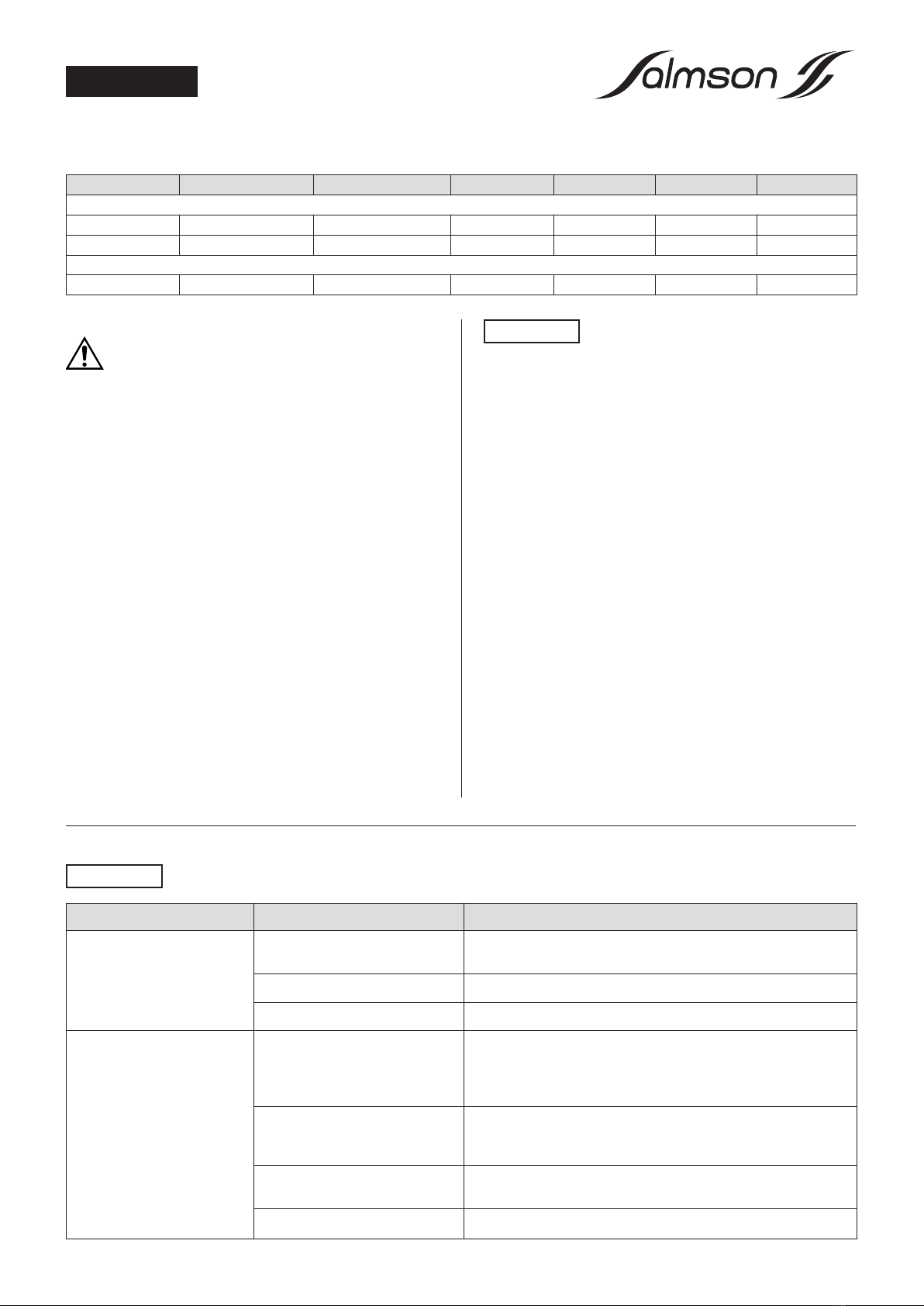
6.1 Réglages
La vanne d’équilibrage (rep. 9) ontrôle la pression différentielle et
ajuste la se tion de passage pour maintenir le débit à la valeur
préréglée. Les valeurs indiquées dans le tableau i-dessous sont
réglées en usine.
ATTENTION !
ATTENTION !
FRANÇAIS