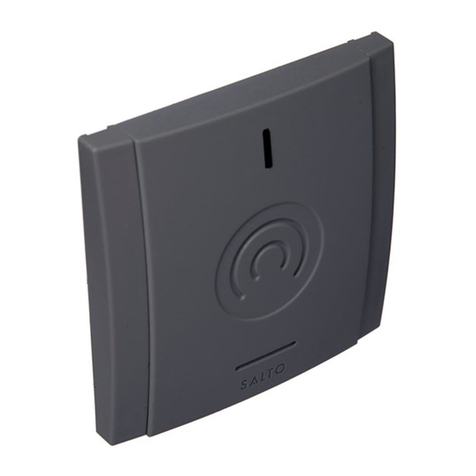
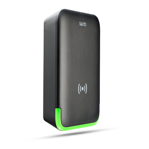
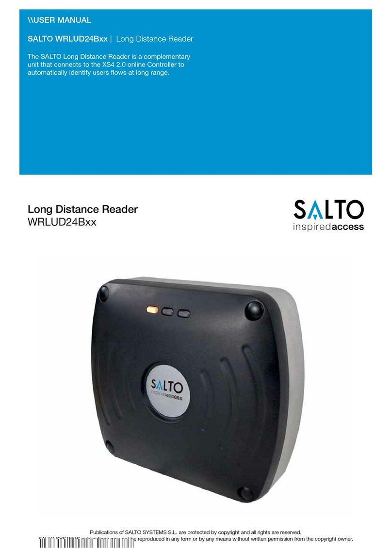
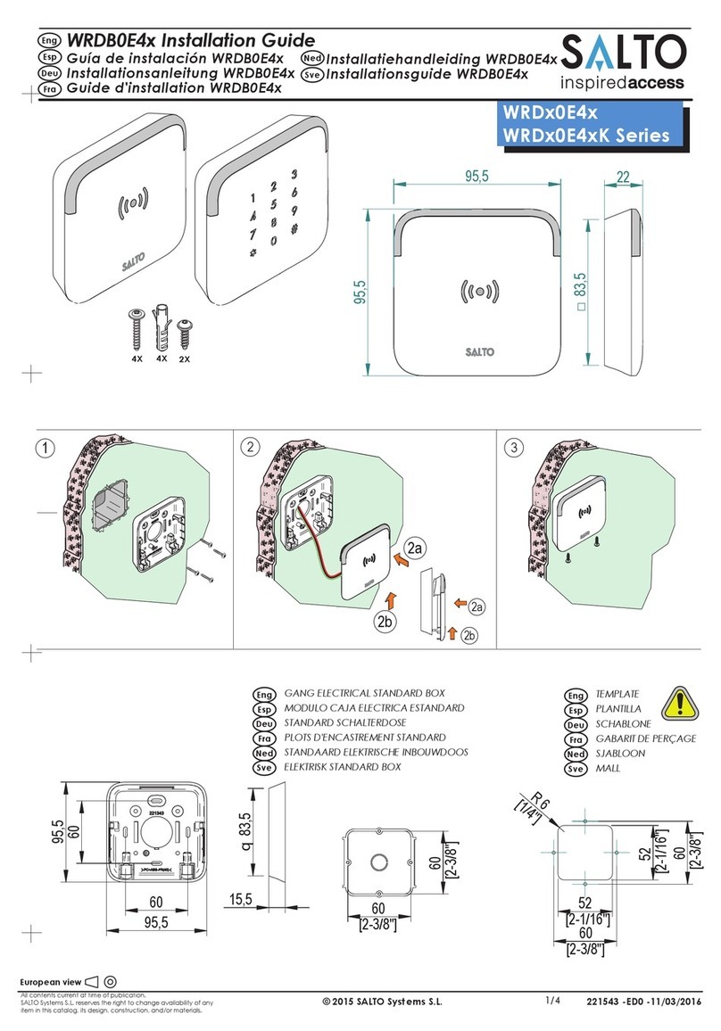
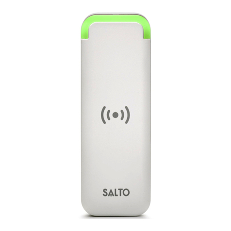
Salto WRM 9000 User manual

All contents current at time of publication.
SALTO Systems S.L. reserves the right to change availability of any
item in this catalog, its design, construction, and/or materials. 220360 -ED1 -27/04/2011
©2010 SALTO Systems S.L.
WRMPK
1/8
83
83 13,5
83
83 13.5
LECTORES
READERS
WANDLESER
LECTEURS
Proximity
Key Pad
MIFARE
®
DESFire®
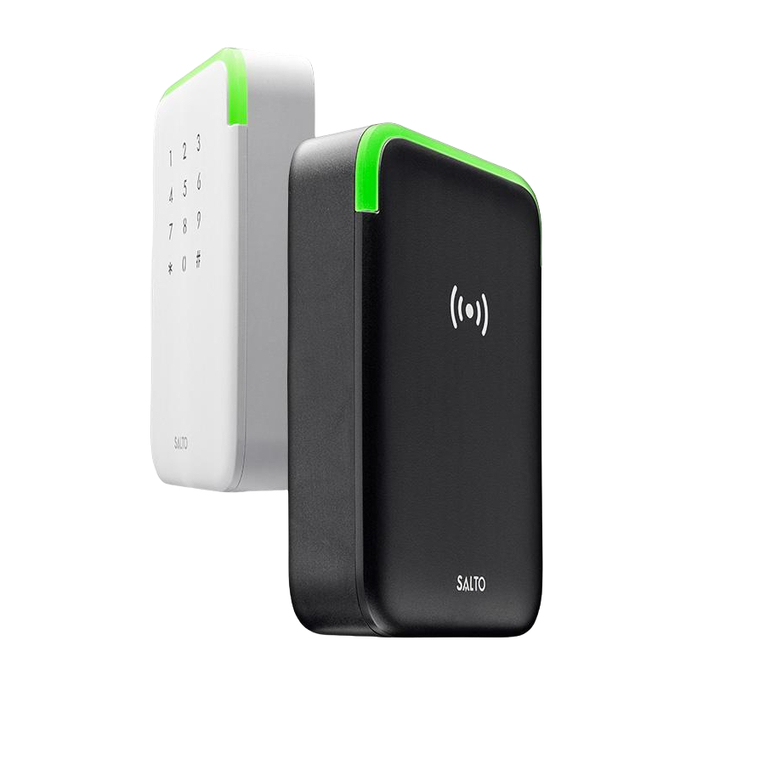
WRM 9000
WRM 9001

All contents current at time of publication.
SALTO Systems S.L. reserves the right to change availability of any
item in this catalog, its design, construction, and/or materials. 220360 -ED1 -27/04/2011
©2010 SALTO Systems S.L. 2/8
83
83
60
60
60
60
52
52
R6
MARCO ANTIVANDALICO
ANTIVANDALIC FRAME
SICHERHEITSRAHMEN
MONTAGE ANTI-VANDAL
60 7
110
110
91
91
TORX-10 TAMPER
TORX 10
WRMBL1
WRMFWAV
BASE BAJA SIMPLE -MONTAJE DE EMPOTRAR
LOW SINGLE BASE - FLUSH MOUNTING
MONTAGE MIT 1-FACH UP-RAHMEN
EMBASE SIMPLE - MONTAGE À ENCASTRER
1 MODULOS CAJA ELECTRICA ESTANDARD
1 GANG ELECTRICAL STANDARD BOX
1-FACH STANDARD SCHALTERDOSE
1 PLOTS D'ENCASTREMENT STANDARD
PANEL METALICO
METAL PLATE
METALLPLATTE
PLAQUE METALLIQUE
PLANTILLA
TEMPLATE
SCHABLONE
GABARIT DE PERCAGE
WRMxxxx
INCLUIDO
INCLUDED
INKLUDIERT
INCLURE

All contents current at time of publication.
SALTO Systems S.L. reserves the right to change availability of any
item in this catalog, its design, construction, and/or materials. 220360 -ED1 -27/04/2011
©2010 SALTO Systems S.L. 3/8
83
165
71 7
2 MODULOS CAJA ELECTRICA ESTANDARD
2 GANG ELECTRICAL STANDARD BOX
2-FACH STANDARD SCHALTERDOSE
2 PLOTS D'ENCASTREMENT STANDARD
PANEL METALICO
METAL PLATE
METALLPLATTE
PLAQUE METALLIQUE
60
71
52
R6
60
60
60
BASE BAJA DOBLE -MONTAJE DE EMPOTRAR
LOW DOUBLE BASE - FLUSH MOUNTING
MONTAGE MIT 2-FACH UP-RAHMEN
EMBASE DOUBLE - MONTAGE ENCASTRER
EJEMPLOS DE APLICACION
APPLICATION EXAMPLES
BEISPIEL ZUSAMMENSTELLUNG
EXEMPLES D'APPLICATION
WRMBL2
PLANTILLA
TEMPLATE
SCHABLONE
GABARIT DE PERCAGE

All contents current at time of publication.
SALTO Systems S.L. reserves the right to change availability of any
item in this catalog, its design, construction, and/or materials. 220360 -ED1 -27/04/2011
©2010 SALTO Systems S.L.
20
83
60
60
83
60
WRMBH1
60
4/8
BASE ALTA SIMPLE - MONTAJE DE SOBREPONER
HIGH SINGLE BASE - SURFACE MOUNTING
MONTAGE MIT 1-FACH AP-RAHME
EMBASE SIMPLE - MONTAGE EN APPLIQUE
O
PANEL METALICO
METAL PLATE
METALLPLATTE
PLAQUE METALLIQUE
PLANTILLA
TEMPLATE
SCHABLONE
GABARIT DE PERCAGE

All contents current at time of publication.
SALTO Systems S.L. reserves the right to change availability of any
item in this catalog, its design, construction, and/or materials. 220360 -ED1 -27/04/2011
©2010 SALTO Systems S.L.
83
165 20
71
71
60
60
5/8
131
O
WRMBH2
BASE ALTA DOBLE-MONTAJE DE SOBREPONER
HIGH DOUBLE BASE - SURFACE MOUNTING
MONTAGE MIT 2-FACH AP-RAHMEN
EMBASE DOUBLE - MONTAGE EN APPLIQUE
PANEL METALICO
METAL PLATE
METALLPLATTE
PLAQUE METALLIQUE
PLANTILLA
TEMPLATE
SCHABLONE
GABARIT DE PERCAGE

All contents current at time of publication.
SALTO Systems S.L. reserves the right to change availability of any
item in this catalog, its design, construction, and/or materials. 220360 -ED1 -27/04/2011
©2010 SALTO Systems S.L. 6/8
CABLEADO
WIRING
ANSCHLUSS
CABLAGE
Posición del Jumper "METAL" en panel
metálico y con WRMFWAV.
"METAL" Jumper´s position in metalic
plate or WRMFWAV.
Position der Steckbrücke bei
Verwendung auf Metall oder in
Kombination mit WRMFWAV
Posittion du cavaller pour un montage
sur une plaque métallique ou
WRMFWAV
* NOTA : ! IMPORTANTE ¡
ALOJAMIENTO SOBRE PANEL
METALICO , SEGUN PLANTILLA.
* NOTE : WARNING !!
FOR METAL PLATE MOUNTING,
FOLLOW THE TEMPLATE.
METAL
Nota 1 : Los cables 2 & 3 deben
pertenecer al mismo par trenzado.
Nota 2 : Los cables 4 & 3 deben
pertenecer al mismo par trenzado.
Nota 3 : Para alcanzar 100 m. entre el lector
y el control, utilizar cable tipo
UTP CAT 5 y respetar lo descrito
en la Nota 1 y 2. (Sólo CU5000)
Nota 4 : Conexiones calefactor
Nota 5: Para alcanzar 100m entre el
calefactor y la fuente de
alimentación, utilizar cable de red
de 3 núcleos y 0,75mm2 de área de
conductor por núcleo
Note 1 :2 & 3 wires have to belong
to the same twisted pair.
Note 2 :4 & 3 wires have to belong
to the same twisted pair.
Note 3 : To reach 100 m between thereader and
the control unit , the cable has to be UTP
CAT 5 type and the technician has to
make the connections shown above.
(Only CU5000)
E
MIN. 50 cm
METAL
ATTENTION- Information for a good functioning.
ACHTUNG- Wichtig für eine ordnungsgemäBe Funktion
ATTENTION- Information pour un bon fonctionnement.
ATENCION- Información para un correcto funcionamiento.
Conexión a :
Connection to:
Anschluss für:
Connexion au:
WRMPK
Note 1 : Anschluss 2 & 3 müssen mit einem
verdrilltem Adernpaar geführt werden.
Note 2 : Anschluss 3 & 4 müssen mit einem
verdrilltem Adernpaar geführt werden.
Note 3 :Um die Entfernung von 100 m zwischen
Wandleser und Steuereinheit zu
gewährleisten, muss ein Kabel von Typ UTP
CAT 5 verwendet und It.Beschreibung
angeschlossen werden. (Nur CU5000)
Note 4: Anschluss Heizung.
Note 5 : Um zwischen Heizung Netzteil 100m zu
erreichen, verwenden Sie ein Kabel 3x0,75mm2
* ACHTUNG: ! WARNUNG¡
BEI VERWENDUNG AUF METALL
AUSNEHMUNG LT. SCHABLONE DURCHFÜHREN.
* NOTE : ! ATTENTION ¡
POUR L'UTILISATION D'UNE PLAQUE
METALLIQUE VOIR LE GABARIT DE PERCAGE.
Conexiones entre el lector y la unidad de control
Reader-control electrical connections Elektrischer Anschluss Wandleser-Steuereinheit
Connexions électriques entre le lecteur et le carte de gestion
Note 1 : L'accompagnant du connecteur 2
doit être raccordé sur le connecteur 3.
Note 2 : L'acompagnant du connecteur 4
doit être raccordé sur le connecteur 3.
Note 3 : Il ne doit pas avoir plus de 100 m
entre le lecteur et l'unité de contrôle.
Vous devez utiliser une câble UTP
CAT 5 pour faire vos raccordements.
(CU5000 Uniquement)
F
D
LECTOR
READER
LECTEUR
LESEN
*Note 3
4
3
2
1
6
54
3
2
1
5
*Note 5
*Note 4
CONTROL
STEUEREINHEIT
GND
12v DC -MIN. 500mA.
100
Circuito Conector
Circuit Connector
Circuit-Anschluss
Circuit Connecteur
Eng
Note 4 : Heater connections.
Note 5 : To reach 100m (between the heater
and the power supply), the cable has to
be a main cable, three cores, 0.75 mm2
conductive area per core.
Note 4 : Résistance chauffante.
Note 5 : Pour atteindre les 100 mètres entre la
résistance chauffante et l’alimentation, il
est nécessaire d’utiliser un câble de
réseau à 3 noyaux, 0,75mm2 de surface
conductrice par noyau.
All contents current at time of publication.
SALTO Systems S.L. reserves the right to change availability of any
item in this catalog, its design, construction, and/or materials. 220360 -ED1 -27/04/2011
©2010 SALTO Systems S.L.
WRMPK
WRMPK
7/8
Conexión a :
Connection to:
Anschluss für:
Connexion vers:
WRM 9000
WRM 9001
TECLADO
KEY PAD
TASTATUR
CLAVIER A CODES
E
Eng
F
D
Declaración de conformidad
Por medio de la presente Salto Systems S.L. (Pol. Lanbarren C/Arkotz,9 - 20180 Oiartzun – Spain - CIF B20708517), declara que este
equipo cumple con los requisitos esenciales y cualesquiera otras disposiciones aplicables o exigibles de la Directiva 1999/5/CE o
la Directiva 89/336/EEC. Podrá encontrar una copia de la declaración de conformidad original en la siguiente dirección de Internet:
http://www.saltosystems.com
Todos los modelos de proximidad son “Receiver class 3”.
Declaration of conformity
By means of the present Salto Systems S.L. (Pol. Lanbarren C/Arkotz, 9 - 20180 Oiartzun - Spain - CIF B20708517), declares tha
t
this equipment fulfills the essential requirements and any other applicable or indispensable dispositions of the Directive 1999/5/CE
or the Directive 89/336/EEC. You will be able to find a copy of the original declaration of conformity at the following Interne
t
address: http://www.saltosystems.com
A
ll proximity models are "Receiver class 3".
Déclaration de conformité
Par le biais de celle-ci, Salto Systems S.L. (Pol. Lanbarren C/Arkotz, 9 - 20180 Oiartzun – Spain - CIF B20708517), déclare être
conforme aux normes essentielles et n’importe quelles autres dispositions applicable et exigibles des Directives 1999/5/CE ou
89/336/EEC. Vous pourrez trouver une copie de la déclaration de conformité originale sur le site internet suivant:
http://www.saltosystems.com
Tous les modèles de proximité sont “Receiver class 3”.
Konformitätserklärung
Hiermit erklärt Salto Systems S.L. (Pol. Lanbarren C/Arkotz, 9 – 20180 Oiartzun – Spanien – UID-Nr. B20708517), dass sich
dieses Produkt in Übereinstimmung mit den grundlegenden Anforderungen und den relevanten Vorschriften der Richtline
1999/5/EG bzw. 89/336/EWG befindet. Die Kopie der Konformitätserklärung im Originalwortlaut ist auf folgender Website zu finden:
http: http://www.saltosystems.com
A
lle Proximity-Modelle sind “Receiver class 3”.

All contents current at time of publication.
SALTO Systems S.L. reserves the right to change availability of any
item in this catalog, its design, construction, and/or materials. 220360 -ED1 -27/04/2011
©2010 SALTO Systems S.L.
SOLO PARA MODELOS DE PROXIMIDAD
Nota: estos dispositivos han sido probados cumpliendo los requerimientos de un dispositivo digital de Clase B, de acuerdo con la
normativa FCC apartado 15. Estos requerimientos han sido establecidos para garantizar una protección contra las interferencias
perjudícales dentro de un entorno residencial. Estos dispositivos pueden generar, utilizar o incluso irradiar energía po
r
radiofrecuencia, y si no se instalan y utilizan aplicando dichos requerimientos, estas pueden producir interferencias que
perjudiquen las comunicaciones por radiofrecuencia. Aun así, no hay garantía de que dichas interferencias perjudiciales no
puedan producirse en una instalación concreta. Si estos equipos causan interferencias perjudiciales en receptores de radio o
televisión, y no se resuelven apagando y encendiendo el receptor, recomendamos al usuario en intentar corregir dichas
interferencias aplicando alguna o varias de estas medidas.
Reorientación o recolocación de la antena receptora.
Aumentar la distancia entre el dispositivo y el receptor
oConecte el dispositivo a una salido del circuito diferente a la que está conectada el receptor.
oConsulte al distribuidor o a un técnico con experiencia en radio y televisión.
ONLY FOR PROXIMITY MODELS
Note: This equipment has been tested and found to comply with the limits for a Class B digital device, pursuant to part 15 of the
FCC Rules. These limits are designed to provide reasonable protection against harmful interference in a residential installation.
This equipment generates, uses, and can radiate radio frequency energy and, if not installed and used in accordance with the
instructions may cause harmful interference to radio communications. However, there is no guarantee that interference will no
t
occur in a particular installation. If this equipment does cause harmful interference to radio or television reception, which can be
determined by turning the equipment off and on, the user is encouraged to try to correct the interference by one or more of the
following measures:
Reorient or relocate the receiving antenna.
Increase the separation between the equipment and receiver.
oConnect the equipment into an outlet on a circuit different from that to which the receiver is connected.
oConsult the dealer or an experienced radio/TV technician for help.
SEULEMENT POUR LES MODELES DE PROXIMITÉ
Remarque: cet appareil a été testé conforme aux normes d’un dispositif numérique de Class B, et conforme aux normes FCC
chapitre 15.
Ces normes ont été établies pour assurer une protection contre les mauvaises interférences dans des environnements résidentiels.
Ces dispositifs peuvent générer, utiliser ou même irradier de l’énergie de radiofréquence et s’ils ne sont pas installés ou utilisés
suivant ces normes, ces dispositifs peuvent produire des interférences qui portent atteinte aux communications par radiofréquence.
Malgré ça, il n’existe aucune garantie que de t’elles interférences puissent se produire dans une installation précise. Si ces
appareils causent des interférences sur des récepteurs de radio ou de télévision, et ne peuvent pas être résolues en éteignant ou
allumant le récepteur, nous conseillons aux usagers d’essayer de corriger ces interférences en appliquant l’une de ces mesures :
Réorienter ou déplacer l’antenne du récepteur.
Accroitre la distance entre l’appareil et le récepteur
oConnecter l’appareil a une borne de sortie différente à celle où est connecté le récepteur.
oConsulter votre distributeur ou un technicien spécialisé en radio ou télévision.
E
Eng
F
8/8
www.saltosystems.com
This manual suits for next models
2
Table of contents
Other Salto Card Reader manuals

Salto
Salto XS4 Mini User manual

Salto
Salto NCoder EC Series User manual

Salto
Salto WRDx0E4 Series User manual

Salto
Salto WRDx0A4 Series User manual

Salto
Salto EC20DR User manual

Salto
Salto WRDx0A4 Series User manual

Salto
Salto WRDx0E4x Series User manual

Salto
Salto WRLUD24B series User manual

Salto
Salto XS4 Mini User manual

Salto
Salto WRD0B User manual