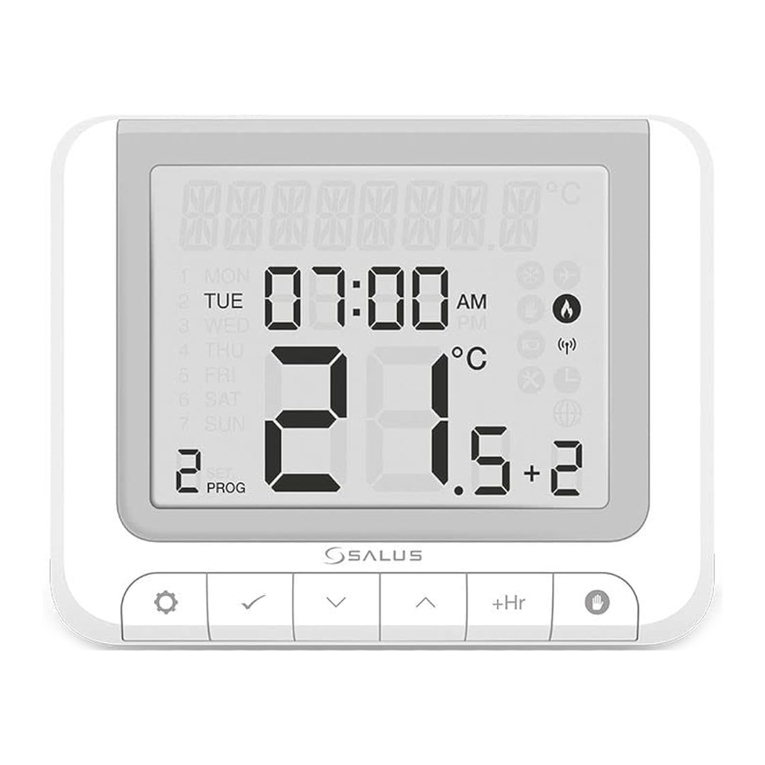
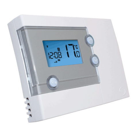
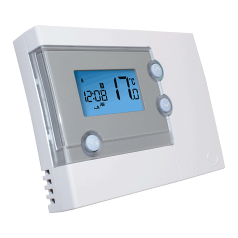
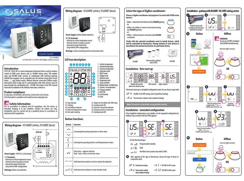
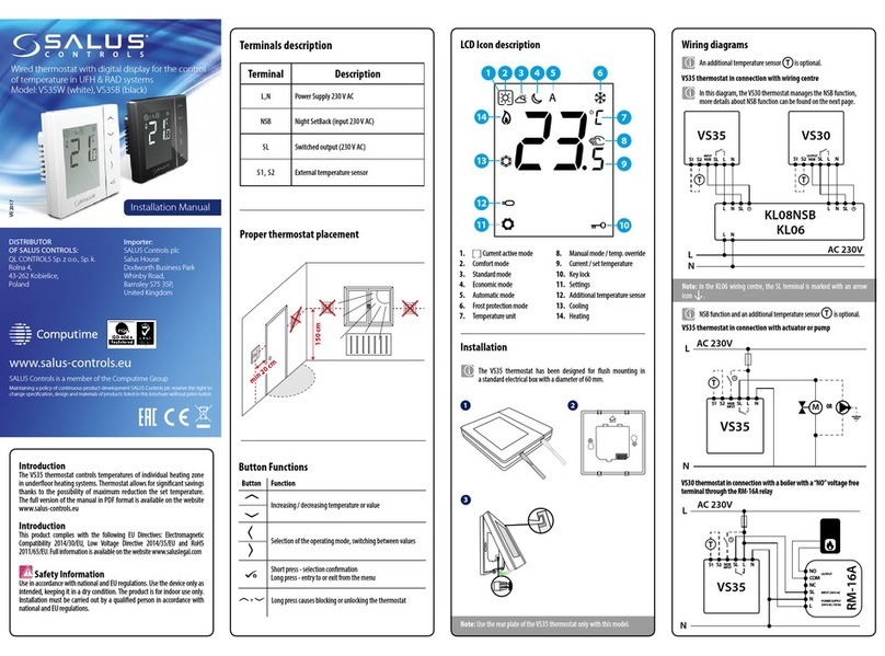
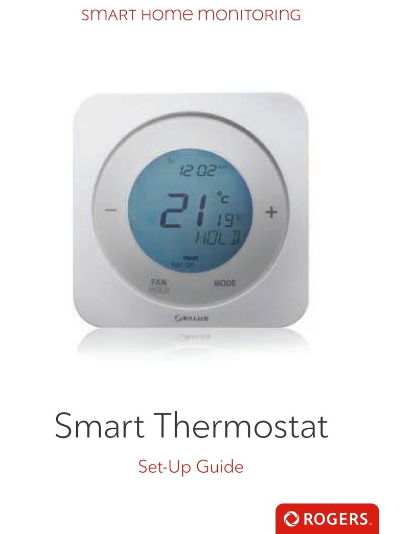
Salus ST620ROF User manual

Programmable RF Room Thermostat
with One Touch Energy Saving
Override Control
CONTROLS
INSTRUCTION MANUAL
Instruction Manual
Model: ST620ROF
SALUS ST620ROF Manual 003.qxp_89 11/08/2015 09:44 Page 1

02 ST620ROF INSTRUCTION MANUAL
PRODUCT COMPLIANCE
This product complies with the essential requirements of the following EC Directives:
•Electro-Magnetic Compatibility directive 2004/108/EC
•EC Marking directive 93/68/EEC
•R&TTE Directives 99/5/EC
SAFETY INFORMATION
These instructions are applicable to the Salus Controls model stated on the front cover of this manual only,
and must not be used with any other make or model.
These instructions are intended to apply in the United Kingdom only, and should be followed along with
any other statutory obligations.
This accessory must be tted by a Competent person, and installation must comply with the guidance
provided in the current editions of BS7671 (IEEWiring Regulations) and Part ‘P’of the Building Regulations.
Failure to comply with the requirements of these publications could lead to prosecution.
Always isolate the AC Mains supply before installing or removing the Integral RF Boiler Control to the
boiler.
When tting or replacing the batteries, do not mix old and new batteries together.
Do not use rechargeable batteries.
Please leave these instructions with the end user where they should be kept in a safe place for future
reference.
SALUS ST620ROF Manual 003.qxp_89 11/08/2015 09:44 Page 2

INTRODUCTION
A programmable thermostat is a device that combines the functions of both a room thermostat and
heating controller into a single unit. The programmable thermostat is used to switch the heating system
by means of time and temperature change. This unit is not like a standard programmer. It works by
controlling the temperature according to a series of programmed settings that take eect at dierent
times of the day.
The ST620ROF from Salus Controls is a stylish and accurate 5/2 or 7 day programmable electronic
thermostat with a large, easy to read Liquid Crystal Display (LCD).This programmable thermostat has been
specically designed to be used Volt Free. Unlike ordinary single unit design programmable thermostats,
this is a new type of unit that separates the operational functions into two units.
The Receiver is used for wiring connections and heat on/o control. The ST620 provides the user interface
and temperature sensing / control. The two units are linked together by a Radio Frequency (RF) signal.
The use of the revolutionary Touch Ring technology makes for simple usage, and is coupled with a unique,
smart design. The LCD display will show the current room temperature and the‘one touch’operation makes
the ST620ROF easy to operate.
ST620ROF INSTRUCTION MANUAL 03
SALUS ST620ROF Manual 003.qxp_89 11/08/2015 09:44 Page 3

04 ST620ROF INSTRUCTION MANUAL
FEATURES
• Touch Ring Technology
• Large LCD with White Backlight
• Radio Controlled Clock (RCC)
• Manual Time / Date Setting Option
• Holiday Function
• Service Function
ST620ROF Features
• One Touch Energy Saver Override Control (RF)
• Volt free switching option
• 5/2 or 7 day programming exibility
• Built-in start up programming for quick installation
• Frost protection
• Large, easy to read display with blue backlight
• Burner on symbol
• Easy to use programming
• User friendly
SALUS ST620ROF Manual 003.qxp_89 11/08/2015 09:44 Page 4

ST620ROF INSTRUCTION MANUAL 05
INSTALLATION
Please read the important safety information at the start of this manual before you begin to install the
device.
The ideal position to locate the ST620 programmable thermostat is about 1.5m above oor level. It should
be mounted in a location where the thermostat is accessible, reasonably lit and free from extremes of
temperature and draughts. Do not mount the thermostat on an outside wall, above a radiator or in a
location where it may be subjected to direct sunlight.
The ST620 should be mounted in a location where it will not come into contact with moisture or
condensation, as this can aect the Touch Ring operation.
To ensure trouble free reception for both the Radio Controlled Clock (RCC) and the Radio Frequency (RF)
signal, always ensure that the programmable thermostat is mounted away from any possible sources of
interference (such as radios, TV sets, computers, etc.), and is not mounted on or in close proximity to large
metal objects. Installing the ST620 in enclosed areas such as cellars and basements is not recommended.
SALUS ST620ROF Manual 003.qxp_89 11/08/2015 09:44 Page 5

06 ST620ROF INSTRUCTION MANUAL
CONNECTING THE ST620ROF RECEIVER
NOTE: All electrical installation work should be carried out by a suitably qualied Electrician or other competent
person. If you are not sure how to install this digital thermostat consult either with a qualied electrician, heating
engineer or your boiler / heating system supplier for advice on how to continue.
The ST620ROF Receiver should be mounted in a suitable location that is both accessible for the connection of mains
and control wiring, and allows good reception of the RF signal. The Receiver needs a 230V AC mains supply to
operate, and this should be fused appropriately (16A max.).
The Receiver should be mounted in a location where it will not come into contact with water, moisture or
condensation. There are few electrical connections required to the ST620ROF, and these connections should be
made to the terminal block inside the Receiver. No Earth connection is required for the correct and safe operation
of the ST620ROF, but a parking terminal is provided to connect an Earth wire if one is present.
These electrical connections are shown in the table below:
Terminal Function
COM Common Contact
NO Normally Open Contact
Earth Parking (No electrical connection)
L Incoming Mains - Live
N Incoming Mains - Neutral
SALUS ST620ROF Manual 003.qxp_89 11/08/2015 09:45 Page 6

RECEIVER WIRING TERMINALS
The receiver cover can be removed from its back plate by
unscrewing the grub screws under the front face and slowly pull
them apart .
Please note: These screws DO NOT need to be fully removed.
Once the cover is fully removed the terminals will become
exposed ready for installation.
ST620ROF INSTRUCTION MANUAL 07
230V
230V
BOILER
230V Switching - Combination Boiler
BOILER
230V
24V
BOILER
Volt Free - Combination Boiler
BOILER
SALUS ST620ROF Manual 003.qxp_89 11/08/2015 09:45 Page 7

2. INSTALLATION
ST620 Programmable Room Thermostat
Getting Started…
Installing the ST620 Batteries
To open the case of the ST620, undo the securing screw on the
bottom.
Now pull the screw down until it stops, then carefully separate the
two halves of the case by gently pulling out an upwards direction.
You will now see the battery compartments on the rear of the front
fascia as shown.
Ensure that the batteries are inserted correctly and check the
polarity.
08 ST620ROF INSTRUCTION MANUAL
SALUS ST620ROF Manual 003.qxp_89 11/08/2015 09:45 Page 8

As soon as the batteries have been inserted, the ST620 will power up for the rst time and behave
in thefollowing way: All the segments on the display along with the display backlight will be
turned on as shown.
The ST620 will now prompt you to choose a language. If you require ENGLISH press OK.
If you require a dierent Language use the touch ring to scroll through the language options then
press OK.
The ST620 at this point will be in AUTO and at factory default settings. Changing default settings
will be explained in sections 4 & 5. You will also notice that the time at the top of the LCD is
ashing. This will continue to ash until the unit picks up the RCC (Radio Controlled Clock) signal
and displays the correct time. More information on the RCC can be found on page 28.
Now put the ST620 front fascia in a safe place so you can mount the ST620 back plate. The back
plate is easily xed to the wall and uses industry standard mounting positions. We recommend
that you continue with the back plate mounting before starting to program the ST620.
POWERING UP THE ST620 FOR THE FIRST TIME
ST620ROF INSTRUCTION MANUAL 09
SALUS ST620ROF Manual 003.qxp_89 11/08/2015 09:45 Page 9

Note: If you do not wish to mount the ST620 on the wall, use the stand provided and
assemble the ST620 front and back housing. Remember to tighten the screw at the bottom.
Wall Mounting Guidelines
The ST620 should be mounted in a location where the thermostat is accessible, reasonably lit and
free from extremes of temperature and draughts. Do not mount the thermostat on an outside wall,
above a radiator or in a location where it may be subjected to direct sunlight.
The ST620 should be mounted in a location where it will not come into contact with moisture or
condensation as this can aect the Touch Ring operation. To ensure trouble free reception for both the Radio Controlled Clock
(RCC) and the Radio Frequency (RF) signal. Always ensure that the programmable thermostat is mounted away from any
possible sources of interference (such as radios, TV sets, computers, etc.), and is not mounted on or in close proximity to large
metal objects. Installing the ST620 in enclosed areas such as cellars and basements is not recommended.
NOTE: The ideal position to locate the ST620 is about 1.5m above oor level.
RF Transmission
The receiving range between ST620 and the RF Boiler Control is around 100 metres in open air, however many factors can
aect the RF transmission and shorten the operating distance, e.g. shielding by thick walls, foil back plasterboard, metal objects
such as ling cabinets, general RF interference, and so on.
The operating range is generally around 30 metres, which is large enough for most
household applications.
Mounting the Back plate
Use the screws and anchors supplied to mount the ST620 back plate in your chosen
position. Now attach the ST620 front fascia to the back plate. Remember to tighten the
securing screw.
SURFACE MOUNT STAND SUPPLIED
10 ST620ROF INSTRUCTION MANUAL
SALUS ST620ROF Manual 003.qxp_89 11/08/2015 09:45 Page 10

‘A’ ‘A’
One Touch Override (OTO)
The OTO can be mounted anywhere inside the property for convenience.
We suggest mounting the unit at the main entry /exit of the property.
1. To begin installation remove the front cover by sliding it up from the back plate.
2. Mark and drill two holes at points ‘A’. Fix the OTO back plate to the wall
using the screws and anchors provided.
INSTALLATION OF ONE TOUCH OVERIDE
ST620ROF INSTRUCTION MANUAL 11
SALUS ST620ROF Manual 003.qxp_89 11/08/2015 09:45 Page 11

12 ST620ROF INSTRUCTION MANUAL
3. Insert the two AAA batteries (supplied) into the bottom rear of the front cover
4. Position the front cover abovethe back plate and slide down until the
cover is in line with back plate
SALUS ST620ROF Manual 003.qxp_89 11/08/2015 09:45 Page 12

ST620ROF INSTRUCTION MANUAL 13
1. Press the SYNC button for 3 seconds then release, the bottom switch will
become red.
(SYNC Button).
(Note: Once paired, the bottom switch will turn green).
SETTING UP RF COMUNICATION BETWEEN ST620ROF
2. Activate ST620 into pairing mode. To access the Menu screens on the ST620RF,
press the OK key twice. The rst menu displayed is the PROGRAM menu:
3. Use the Touch Ring to scroll through the Menus to locate the pair option then
press OK key
4. Press OK key again activate pairing mode. PAIR will stop ashing and the pair
icon will appear
5. The display will change to show a rundown timer:
SALUS ST620ROF Manual 003.qxp_89 11/08/2015 09:45 Page 13

1. Press the SYNC button for 3 seconds on the
One Touch Overide and then release.
(SYNC Button)
(Note: Once paired, the bottom switch will turn green).
SETTING UP RF COMUNICATION BETWEEN ST620ROF
14 ST620ROF INSTRUCTION MANUAL
2. Press the SYNC button for 3 seconds then release,
the bottom switch will become red.
(SYNC Button)
SALUS ST620ROF Manual 003.qxp_89 11/08/2015 09:45 Page 14

SYNC button
Auto
Setback
Out Button
Key/Operation
OUT
SYNC
SETBACK
AUTO
Functions
OUT Switches the override feature on or o
Puts the OTO into pairing mode
to allow wireless (RF) connection
Allows selection of a 2°C, 4°C
or 6 °C setback temperature setting
Lowest set temperature in the
ST620 is used (or manual override
setpoint, or programme setting of
that day)
1 Selecting the set back temperature
On the Side of the One Touch Override (OTO) you
will see a vertical slide switch. The slide switch
allows you to select an override temperature that
will operate when the OTO is activated. If you select
2ºC, 4ºC or 6ºC then the active temperature
selected on the RT500 programmable room
thermostat will be reduced by either 2ºC, 4ºC or 6ºC.
If you select AUTO then the ST620 will switch to the
lowest temperature selected on the ST620.
2. Activating the OTO On the front cover of the One
Touch Override (OTO) you will see that there is a
large button, press this to activate the OTO. When
activated the red light behind the word“OUT” will
ash.
To deactivate the OTO press the button again, the
light will ash once and go out.
ONE TOUCH OVERIDE INTERFACE AND CONTROLS
ST620ROF INSTRUCTION MANUAL 15
SALUS ST620ROF Manual 003.qxp_89 11/08/2015 09:45 Page 15

Indicator Description Function
Clock Display Displays the day and time
Temperature indicator Displays set or measured temperature
Alphanumeric Display Displays menu and other status messages
Programme Number Displays the number of the
indicator active (selected) programme
Heat Mode indicator Indicates heating output is turned on.
Holiday indicator Indicates Holiday operation mode is selected
Battery Status Indicates battery is low
RF Signal indicator Indicates the unit is transmitting
a wireless signal
RCC indicator Indicates unit is searching for radio controlled clock signal
Service indicator Indicates Service function is active
Frost Mode indicator Indicates frost setting is turned on
Touch Lock indicator Indicates touch lock is activated
There are few user controls for the ST620, making the programmable thermostat very easy to operate.The controls are a Touch
Ring (which surrounds the user display), two touch sensitive buttons, a reset button and a slide operated switch mounted on
the side of the thermostat. These controls are shown below, along with a description of each of their functions.
USER CONTROL FUNCTION
16 ST620ROF INSTRUCTION MANUAL
SALUS ST620ROF Manual 003.qxp_89 11/08/2015 09:45 Page 16

USER CONTROL FUNCTION SUMMARY ST620:
Key / Operation Functions
Touch Ring (move clockwise) Increases the set temperature and scrolls through the menu selection
Touch Ring (move anti- clockwise) Decreases the set temperature and scrolls through the menu selection
OK Key Enters Menu or conrms a menu selection
Arrow (Back) Key Single touch- sets the unit back 1 step.
Hold for 2 seconds sets unit back to normal mode
Reset Button Resets the thermostat to default (original factory) settings
Slide Switch Activates and deactivates the key lock function (prevents accidental changes)
ST620ROF INSTRUCTION MANUAL 17
SALUS ST620ROF Manual 003.qxp_89 11/08/2015 09:45 Page 17

Programme Output Weekday Weekend
1ON 6:00AM 6:00AM
TEMP 21ºC 21ºC
2ON 8:00AM 8:00AM
TEMP 14ºC 14ºC
3ON 11:00AM 11:00AM
TEMP 21ºC 21ºC
4ON 1:00PM 1:00PM
TEMP 14ºC 14ºC
5ON 4:00PM 4:00PM
TEMP 21ºC 21ºC
6ON 9:00PM 9:00PM
TEMP 14ºC 14ºC
Reviewing the Set Temperature
1. AUTO mode is when the thermostat is displaying the room temperature.
2. If you press the Touch Ring anywhere except the OK and Arrow keys you can check the
set temperature setting.
This will display the current set temperature. The set temperature will be displayed for two
seconds before the LCD changes to display the room temperature again.
The ST620 will go back to AUTO mode without changing the set temperature after 10 seconds
of inactivity, or after pressing the Arrow key.
4. BASIC OPERATION
GETTING STARTED…
ST620 PROGRAMMABLE ROOM THERMOSTAT
YOUR ST620 COMES WITH FACTORY SET DEFAULT
PROGRAM. THE TEMPERATURE AND TIME SETTINGS
HAVE ALREADY BEEN SET. IF THE DEFAULT
PROGRAM MEETS YOUR REQUIREMENT THERE IS
NO NEED TO CHANGE THE DEFAULT PROGRAM.
18 ST620ROF INSTRUCTION MANUAL
SALUS ST620ROF Manual 003.qxp_89 11/08/2015 09:45 Page 18

Manual Override
When the ST620 is in AUTO mode, press the Touch Ring anywhere except the OK
and Arrow keys to enter the manual override mode. The currently set temperature
will be displayed on the LCD and will ash.
When the set temperature is ashing, press the touch ring and move your nger
clockwise to increase the set temperature, or anti-clockwise to decrease the set
temperature. Press OK at any time to conrm the selection.
NOTE: The ST620 will go back to AUTO mode without changing the set
temperature after 10 seconds of inactivity, or after pressing the Arrow key.
When the ST620 is operating in Manual Override mode, the LCD will display
MANUAL instead of AUTO. The manual setting will remain in eect until the next
programme time is reached, or the Manual Override mode is cancelled.
Manual Override mode can be cancelled at any time by pressing and holding the
Arrow key for 2 seconds – this will return the ST620 to AUTO mode.
ST620ROF INSTRUCTION MANUAL 19
SALUS ST620ROF Manual 003.qxp_89 11/08/2015 09:45 Page 19

5. ADVANCED FUNCTIONS
Menu Screen Overview
Press the OK key twice and use the touch ring to
scroll through the Menus, and you can then press
the OK key to select the menu you want to use.
You can scroll through the menus in either direction, depending on the direction you move your nger around the
Touch Ring. The menus are displayed in the order shown in the picture above.
Pressing the Arrow key will return the ST620 to AUTO/MANUAL mode. The programmable thermostat will also return to
AUTO/MANUAL mode after 10 seconds if no Key is pressed.
NOTE: SERVICE and CONTROL are functions that should be carried out by an installer or competent person.
These function are explained in detail on Page 32.
20 ST620ROF INSTRUCTION MANUAL
SALUS ST620ROF Manual 003.qxp_89 11/08/2015 09:45 Page 20
Table of contents
Other Salus Thermostat manuals

Salus
Salus WBRT520TX User manual

Salus
Salus HTRP230 User guide

Salus
Salus RT500 User manual

Salus
Salus iT500 User manual

Salus
Salus T105 RF User manual

Salus
Salus QUANTUM SQ610RF User manual

Salus
Salus ZigBee User manual

Salus
Salus RT510WBC User manual

Salus
Salus RT310 User manual

Salus
Salus RXRT520 User manual
Popular Thermostat manuals by other brands

EPH
EPH CP4-HW-OT Installation and operation guide

Friedrich
Friedrich DWC1 Installation and operation manual

Bpt
Bpt TH124.01 Instructions for use

Nailor
Nailor UNI2-VAV Installation and operation manual

Beok Controls
Beok Controls BOT-205 user manual

Silvercrest
Silvercrest Classic Model L Operating instructions and safety advices