manuals.online logo
Brands
  1. Home
  2. •
  3. Brands
  4. •
  5. Salus
  6. •
  7. Thermostat
  8. •
  9. Salus VS10WRF User manual

Salus VS10WRF User manual

Scan for equipment
Name this equipment
Living room
Connect equipment
Finish
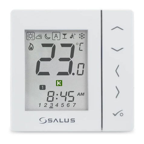
Digital programmable wireless 4 in 1 thermostat
Models: VS10WRF, VS10BRF,
VS20WRF, VS20BRF
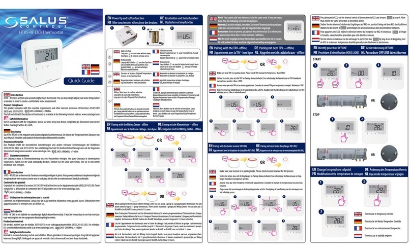
Introduction
VS10..RF / VS20..RF is a room temperature thermostat that is used for wireless
control of iT600 series devices such as: KL08RF wiring centre, TRV radiator
valve and RX10RF boiler receiver. In combination with Universal Gateway
UGE600 this regulator can be controlled over the Internet using SALUS Smart
Home app (Online mode). Without Internet connection (Offline mode)
thermostat works locally, but its communication with other devices must be
done through the coordinating unit - CO10RF. Full version of the PDF manual
instruction is available on the website www.salus-controls.eu
Product compliance
EC Directives: 2014/30/EU, 2014/35/EU, 2014/53/EU i 2011/65/EU.
Full information is available on the website www.saluslegal.com
Power Supply: 4xAAA (alkaline batteries)
S1, S2 Terminals:
- external air or floor temperature sensor
- external contact (occupancy sensor)
- external hot water thermostat
(only with KL10RF configuration)
Montage: surface mounting (need to remove back cover)
Power Supply: 230V AC (L, N terminals)
1, 2 Terminals:
- external air or floor temperature sensor
- external contact (occupancy sensor)
- external hot water thermostat
(only with KL10RF configuration)
Montage: 60mm concealed box
L
S
230V AC
FUSE
T
N
Choose a ZigBee coordinator and prepare it to work with iT600 series
devices:
Firstly with the selected coordinator need to install devices, which
will be controlled by thermostat. Pairing method of each devices is
described in the manual instruction of a particular device.
KL08RF RX10RF
• Online - connected to the Internet via the UGE600 gateway
or
• Offline -the ability to connect to the Internet using
the UGE600 gateway
or
• Offline - without Internet connection with CO10RF
coordinator WARNING!
Do not use CO10RF coordinator
with UGE600 simultaneously.
Enter the wiring centre
number with or ,
Confirm your choice by .
Close the ZigBee network
Open the ZigBee network
Enter the zone number
with or ,
Confirm your choice by .
Wiring diagram - VS20WRF (white), VS20BRF (black)
Wiring diagram - VS10WRF (white), VS10BRF (black)
Installation - first start up
Installation - pairing with KL08RF / KL10RF wiring centre
Online Offline
OR
OR
LCD Icon description
Select the type of ZigBee coordinator:
Button Functions
Safety Information
Use in accordance to national and EU regulations. Use the device as
intended, keeping it in dry condition. Product for indoor use only.
Installation must be carried out by a qualified person in accordance to
national and EU regulations.
VII 2017
VS10WRF
T45 IP30
2 1 L
Probe 230VAC
N
-- --
MCU software*Numbers 88.8 and 8.8
relate to the software version
1. Comfort temperature
2. Standard temperature
3. Economic temperature
4. Automatic mode
5. PARTY mode
6. Holiday mode
7. Antifrost mode
8. Temperature unit
9. Group controller
10. Manual mode / override temp.
11. Current / set temperature
12. Program number
13. AM / PM
14. Lock function
15. Clock
Button Function
Increasing/decreasing temperature or other value
Selecting the operating mode or switching between values
Short press - approve selection
Hold - enter / exit to or from the menu
Hold down these buttons to lock or unlock the keyboard
Hold down these buttons to enter installer mode
+
++
16. Day indicator
17. Settings
18. Low battery indicator
19. External temperature sensor
20. Hot water heating
21. Modes for Hot Water (KL10RF only)
22. Cooling mode ON
23. Internet connection indicator
24. Gateway wireless connection
25. Heating mode ON
ZigBee software
1
8
9
10
11
14
17 16 15
13
12
22
23
24
25
21
20
19
18
2 3 4 5 6 7
Thermostatic radiator
valve (TRV)
1
5
5
2
6
11
3
7
6
4
SALUS
Smart Home
Online Offline
5 sec
5 sec
5 sec
5 sec
Grouping
(Offline only)
Install the wiring centre
according to the instructions
attached to the product.
1
4
2 3
If the simplified configuration is not suitable, run the expanded configuration by
holding 3 keys as below until SEL PROG appears:
After approval of the type of thermostat, choose the type of device to
cooperation with:
Note:Thermostat is set by default as programmable (weekly).
Programmable (weekly)
Underfloor heating
- KL08RF or KL10RF wiring centre (underfloor heating)
Thermostat starts up in a simplified configuration mode.You can choose to pair with:
Daily
Thermostatic radiator
valve (radiator heating)
-Thermostatic radiator valve (radiator heating)
Hot Water timer (works only with KL10RF)
Set the theromstat type:
RX10RF in RX1 mode
RX10RF in RX2 mode
Installation - extended configuration
3
S1 S2
UP
S
T
for 14.4 MCU,
7.3 (VS20..RF), 10.9 (VS10..RF) ZigBee software version
Quick Guide
Note: If thermostat works in AUTO mode, then the overwritten temperature
will be maintained until next program. In manual mode and antifrost mode
temperature change is permanent.
Note:
This action will permanently remove all your settings.
Auto Manual
On O
1
4
2
5
3
6
If you have made an error, need to change your thermostat parameters
or want to return to the factory settings, please follow steps below.
Distributor: Importer:QL CONTROLS Sp. z o.o., Sp.k.
Rolna 4, 43-262 Kobielice, Poland
www.salus-controls.eu
SALUS Controls plc
Salus House, Dodworth Business Park
Whinby Road, Barnsley S75 3SP, United Kingdom
Factory Reset
Pairing thermostat withTRV in Offline mode Pairing thermostat with RX10RF boiler receiver Identification of paired devices
Temperature change
Pairing thermostat withTRV in Online mode
11
1
5
6
7
8
9
10
23
45
67
89
13
15
16
18
17
19
14
Scan for equipment
Name this equipment
Living room
Connect equipment
Finish
Save
0 TRVs on this thermostat
Select TRV(s) for Living room
TRV-1 Living room
1 TRVs on this thermostat
3
WARNING! Do not use CO10RF coordinator with UGE600 simultaneously.
Thermostat will go to the home screen.
Open the tab with the main parameters of the thermostat, set to work with TRV.
Install the RX10RF boiler receiver according to the
instructions attached to the product. Choose proper
mode configuration with RX1/RX2 switch inside of
RX10RF, then prepare regulator for pairing.
Enter the installer mode, select code“00”and confirm it with button.
To set the temperature, press or , and then confirm it with button.
LED diodes on the devices connected to the thermostat will start to blink.
RX10RF in RX1 mode
Run thermostat in extended configuration
mode and select the device type:
RX10RF in RX2 mode
Device is paired with
coordinator, diode on
the TRV will start to blink
orange.
Press to exit the test menu.
Diode on the TRV will
light up once green
and stop blinking.
TRV has been added.
5 sec
5 sec
5 sec
OR
OR
Hold the button for 10 seconds,
The LED on the head should start
to blink red.
10 sec
Install the TRV on the valve
according to the instructions
attached to the product.
Select the device
type - TRV.
Select the device
type - TRV.
Install the TRV on the valve
according to the instructions
attached to the product.
10 11 12
SALUS
Smart Home
2
1
1
2
4
34
3
3
65
3
Open the ZigBee network
Close the ZigBee network.
Scan for equipment
WARNING!
Do not use CO10RF coordinator
with UGE600 simultaneously.
WARNING! In network coordinator can works only with 1 receiver in RX1
mode and 1 receiver in RX2 mode.
Open the ZigBee network
Online Offline
OR
OR
OR
SALUS
Smart Home
5 sec
5 sec
5
Name this equipment
Boiler
Connect equipment
Finish
Close the ZigBee network
OR
6
Online Offline
5 sec
5 sec
5 sec
5 sec
5 sec
3
2
2
4
5 sec
5 sec
5 sec
5 sec
WARNING! You can connect up to 6 heads to one thermostat.

Other manuals for VS10WRF

1

This manual suits for next models

3

Other Salus Thermostat manuals

Salus Optima S User manual

Salus

Salus Optima S User manual

Salus ST101ZB User manual

Salus

Salus ST101ZB User manual

Salus VS35W User manual

Salus

Salus VS35W User manual

Salus iT500 User manual

Salus

Salus iT500 User manual

Salus iT500 User manual

Salus

Salus iT500 User manual

Salus FT100 Owner's manual

Salus

Salus FT100 Owner's manual

Salus Quantum WQ610 User manual

Salus

Salus Quantum WQ610 User manual

Salus RT500BC User manual

Salus

Salus RT500BC User manual

Salus ST620RF User manual

Salus

Salus ST620RF User manual

Salus ERT30 User manual

Salus

Salus ERT30 User manual

Salus Optima S User manual

Salus

Salus Optima S User manual

Salus RT310TX User manual

Salus

Salus RT310TX User manual

Salus AWRT10RF User manual

Salus

Salus AWRT10RF User manual

Salus QUANTUM SQ610RF User manual

Salus

Salus QUANTUM SQ610RF User manual

Salus ERT20RF User manual

Salus

Salus ERT20RF User manual

Salus QUANTUM SQ610RF User manual

Salus

Salus QUANTUM SQ610RF User manual

Salus AS20WRF User manual

Salus

Salus AS20WRF User manual

Salus RT510LG5V User manual

Salus

Salus RT510LG5V User manual

Salus RT310i User manual

Salus

Salus RT310i User manual

Salus TS600 User manual

Salus

Salus TS600 User manual

Salus RT310SPE User manual

Salus

Salus RT310SPE User manual

Salus Quantum SQ610 User manual

Salus

Salus Quantum SQ610 User manual

Salus ST620 User manual

Salus

Salus ST620 User manual

Salus RT510RF User manual

Salus

Salus RT510RF User manual

Popular Thermostat manuals by other brands

White Rodgers 1F80-240 Installation and operation instructions

White Rodgers

White Rodgers 1F80-240 Installation and operation instructions

Lennox ComfortSense 3000 Series Operation manual

Lennox

Lennox ComfortSense 3000 Series Operation manual

Beok Controls TGW60 Series manual

Beok Controls

Beok Controls TGW60 Series manual

Trane TCONT824 installation guide

Trane

Trane TCONT824 installation guide

Drayton Digistat 2 User instructions

Drayton

Drayton Digistat 2 User instructions

Danfoss DEVIreg 610 installation guide

Danfoss

Danfoss DEVIreg 610 installation guide

Honeywell RTH2310 operating manual

Honeywell

Honeywell RTH2310 operating manual

Honeywell T4398 Series manual

Honeywell

Honeywell T4398 Series manual

Johnson Controls TEC2101-3 N2 installation instructions

Johnson Controls

Johnson Controls TEC2101-3 N2 installation instructions

Neptronic EVCBM14NIT2S Specification and installation instructions

Neptronic

Neptronic EVCBM14NIT2S Specification and installation instructions

Thermogroup 5250 Installation & user guide

Thermogroup

Thermogroup 5250 Installation & user guide

Carrier TC -PAC installation instructions

Carrier

Carrier TC -PAC installation instructions

HomeMatic HMIP-eTRV-2 Mounting instruction and operating manual

HomeMatic

HomeMatic HMIP-eTRV-2 Mounting instruction and operating manual

OJ Electronics UTCG-9991 user manual

OJ Electronics

OJ Electronics UTCG-9991 user manual

suntouch SunStat 500700-120 Installing

suntouch

suntouch SunStat 500700-120 Installing

nest G4CVZ user manual

nest

nest G4CVZ user manual

Loreme THL101 Configuration handbook

Loreme

Loreme THL101 Configuration handbook

Atag One Zone quick start guide

Atag

Atag One Zone quick start guide

manuals.online logo
manuals.online logoBrands
  • About & Mission
  • Contact us
  • Privacy Policy
  • Terms and Conditions

Copyright 2025 Manuals.Online. All Rights Reserved.