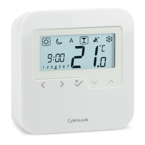
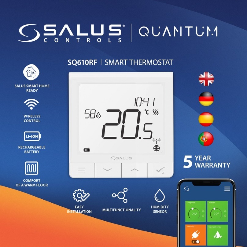
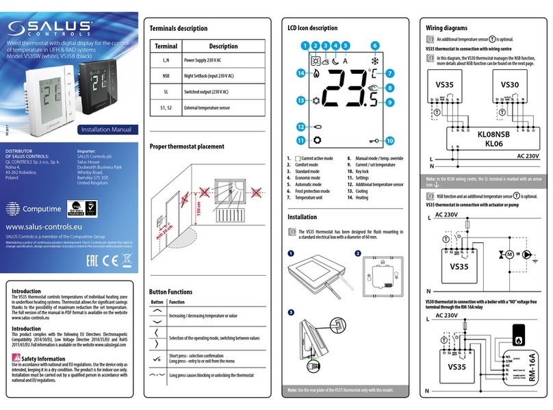
Salus QUANTUM SQ610RF User manual

IX 2019

2
Introduction
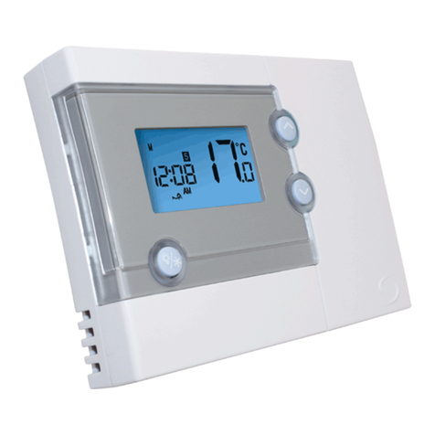
The SQ610RF Quantum is a ZigBee temperature controller for wireless control of iT600 series devices, such as
the KL08RF wiring centre, miniTRV head, RX10RF boiler control module.
In order to control SQ610RF over the Internet or via the SALUS Smart Home mobile app (ONLINE mode), it
must be installed together with the UGE600 Internet gateway (sold separately). From the application level, it is
possible to pair SQ610RF with other system elements, e.g. Smart Plug SPE600, Smart Relay SR600 or window/
door sensor OS600/SW600.
SQ610RF can be used locally without an Internet connection (OFFLINE mode), however, it’s communication
with other devices must be done using the CO10RF coordinator (sold separately).
Full manual in PDF format is available at www.salus-controls.eu site.
Useinaccordancetonationaland EU regulations.Usethe device as intended,keepingit in drycondition. Product for
indoor use only. Installation must be carried out by a qualied person in accordance to national and EU regulations.
Disconnect your equipment before cleaning it with a dry cloth.
Product Compliance
Safety Information
This product complies with the essential requirements and other relevant provisions of Directives 2014/30/ EU,
2014/35/EU, 2014/53/EU and 2011/65/EU. The full text of the EU Declaration of Conformity is available at the
following internet address: www.saluslegal.com.
Package Content:
1) SQ610RF QuantumThermostat
2)Wall mounting plate
3) Self-adhesive mounting tape
4) Mounting screws
5) Manual instruction

3
Polski
Русский
Český English
Before you start:
Charging to full battery level may take up to
24h maximum.
New SQ610RF Quantum Thermostat is partially
charged, however, we recommend you to fully
charge the battery before use.
Connect charger to micro-USB Port which is at
the bottom of SQ610RF Quantum Thermostat to
charge the device.
Wiring diagram (S1, S2 Input)
Symbols explanation:
S – volt-free contact
T – temperature sensor
S1,S2 Terminals:
- air or oor temperature sensor
- external volt-free contact to connect any ON/
OFF switch or occupancy sensor (Hotel card)
Mounting: to mount thermostat you can use
included accesories (mounting screws or self-
adhesive tape). Remove back cover to mount the
plate to the wall. After this just attach thermostat
to the plate (it has built-in magnet).
Please note:
Theideal position to thermostat mountingisabout
1,5m under oor level far from heating or cooling
sources. Thermostat can’t be exposed to sunlight
or any extreme conditions like for example draft.
1 2
3
S1
S2
T
S

4
1. Menu/Settings description + Clock
2. AM/PM
3. Temperature unit
4. Heating indicator (icon is animating when
there is heating demand)
5. Cooling indicator (icon is animating when
there is cooling demand)
6. RF Connection indicator
7. Internet connection indicator
8. Occupancy sensor (hotel card)
9. Key lock function
10. Standby mode icon
11. CurrentTemperature / Setpoint Temperature
12. Holiday mode
13. Temporary override mode
14. Settings icon
15. Baterry status indicator
16. External / Floor temp sensor indicator
17. Schedule program number
18. Schedule mode icon
19. Day indicator/ SET information
20. Current Humidity value
2
8
9
10111214
15
20
19
18
17
16
1
3
4
5
6
7
13
LCD Icon Description

5
Polski English
Русский
Český
Buttons Description
1) Menu button / Return button.
2) In the MAIN SCREEN: Press and hold for 3 sec to change the thermostat operating mode
(Schedule mode / Permanent mode /Temporary override mode).
3) In the SETTINGS SCREEN:
Press and hold for 3 sec to go back without saving the changes.
4) In the PAIRING SCREEN (in SYSTEM TYPE Menu): Press and hold for 3 sec to see other
pairing options.
+
In the MAIN SCREEN - press and hold these buttons together for 3 seconds to LOCK / UNLOCK
the Thermostat keys).
“Up”Button (Increase parameter value/moving on the menu in‘UP’direction)
„Down”Button (Decrease parameter value/moving on the menu in‘DOWN’direction)
1) Press and hold for 3 seconds to POWER UP new device
2)“OK / Tick”Button (Conrm parameter value / Go to the next menu / Save settings)
3) In the MAIN SCREEN: Press and hold for 3 seconds to enter Standby mode
4) In the SETTINGS SCREEN: Press and hold for 3 sec to go back to the MAIN SCREEN & SAVE all the changes.
5) During PAIRING process – hold button for 3 seconds to POWER OFF or REBOOT the thermostat.
Button Function

6
COMPATIBILTY WITH OTHER SALUS CONTROLS DEVICES
QuantumThermostat can work in ONLINE or OFFLINE mode.
At rst step you need to decide in which mode your thermostat will work.
ONLINE MODE OFFLINE MODE
Universal Gateway is
CONNECTED TO THE INTERNET
You can congure and use all your
devices in the Smart Home App
Download the Smart Home
App on your iOS or Android
device for remote access to your
SALUSequipment. SALUS
Smart Home
CO10RF Coordinator - You can use
standard ZigBee network coordinator
toinstall and useyour devices.
Universal Gateway is NOT
CONNECTED TO THE INTERNET
You can use your devices locally
without the SmartHome App.
Gateway works in this mode as
standard ZigBee coordinator.
OR
Compatibile devices:
KL08RF – Wiring Centre for
8-zone underoor heating
(UFH).
TRV (Thermostatic
Radiator Valve) with
wireless communication.
RX10RF
receiver
SR600*
Smart Relay SPE600*
Smart Plug
Only with Online Mode*
GET IT ON
Download on the

7
Polski English
Русский
Český
First power up sequence
To power on the Thermostat hold
button for 3 seconds...
3 sec.
For easier installation, please make sure you have already added other devices to your ZigBee network, such as
Underoor Heating Control Box (KL08RF) or Radiator heads (TRV’s) etc.
Please note:
Now, choose your language by
„” or „ ” buttons. Conrm
your language by button.
...display will show all icons...
...then thermostat will display
the software version.
MENU / Press for 3 sec
to POWER UP
For more information
scan this code or visit:
www.salus-controls.com
3 sec
Removetheprotection foil
3
2
5
1
4

8
Installation in ONLINE mode
AfterLanguage selection follow below stepstoadd your devicetothe SmartHomeappand pair with other devices:
2
8
7
4
1
SALUS
SmartHome
Go to SALUS Smart Home app
3
Once your thermostat is added to
the app you will see above screen
on the LCD.
9
56

9
Русский
Český Polski English
11 1210
13 14
Name this equipment
SQ610RF Thermostat
Connect equipment
Finish
3
After that thermostat will display
main screen.
Congratulations!You succesfully
congured SQ610RF Quantum
Thermostat.
15

10
Installation in OFFLINE mode
Pairing with Wiring Centre / Control Box (Install the Wiring Centre / Control Box according to the
instructions included with product)
1
23
Open the ZigBee network
4
7
56
Select system type: UNDERFLOOR,
press button to conrm.
Using and buttons select theControl
Box number (press PAIR button on the Control
Box to see its address number). Press
button to conrm.
Use or buttons to select
the zone number and press
button to conrm.
8
Now you can pair your thermostat
with additional zones. Select one
more zone or nish the pairing process
by button.
OR
5 sec.
5 sec.
9
Close the ZigBee network
OR
3
3
5 sec.
5 sec.

11
Русский
Český Polski English
7
54
3
6
Open the ZigBee network
Select system type:
RADIATORS
Now hold antenna button for 10
sec. on all TRV’s which you want
to pair with yourTermostat.
Pairing with TRV radiator head (Install the TRV accordingtotheinstructionsincludedwith
product)
On the LCD you will see the numberof paired
TRV’s. Once all TRV’s are paired - press
button to nish the pairing process.
OR
5 cek.
5 cek.
10sec
12
98
Close the ZigBee network
OR
5 cek.
5 cek.
You can pair up to 6 TRV’s with 1
Thermostat. AllTRV’s have to within
the same room withThermostat.
3
3

12
SQ610RF Full menu structure
Schedule settings
User settings
Admin settings
Language
TIME/DATE
HOLIDAY MODE
THERMOSTAT CALIBRATION
SHOW/HIDE DISPLAY HUMIDITY
SHOW/HIDE DISPLAY FLOOR
STANDBYTEMP SETPOINT
HEAT/COOL
RESET USER SETTINGS
TEMPERATURE SCALE
DISPLAY TEMPERATURE RESOLUTION
1.
HEAT CONTROL ALGORITHM 2.
COOL CONTROL ALGORITHM
S1/S2 INPUT 3.
MINIMUM SETPOINT
MAXIMUM SETPOINT
VALVE PROTECTION 4.
MINIMUMTURN OFF TIME 5.
OPTIMISATION FEATURE 6.
COMFORTWARM FLOOR 7.
PIN CODE
DEVICE INFORMATION 8.
FACTORY RESET 9.
ENGLISH
DANISH
POLISH
...
DISABLE
MO-FR+SA-SU
MO-SU
SINGLE DAYS
Main menu

13
Русский
Český Polski English
Short description of some selected functions
(all functions are described in the full version of the SQ610RF manual):
1. DISPLAY TEMP RESOLUTION: This function determines the resolution of the displayed temperature -
User can temperature set by steps (every 0,5*C or 0,1*C).
2. CONTROL ALGORITHM:This function denes how to control the room temperature. Available options
are: ITLC for Underoor Heating / Radiators / Electrical Heating (that’s advanced algorithm for precise
maintenanceof room temperature),hysteresis+/-0.5°C or+/-0.25°C,THB Actuator(optionrecommended
for systems withTHB auto balancing actuators).
3. S1/S2 INPUT: A oor sensor, an external temperature sensor or an occupancy sensor can be connected
to the S1/S2 input of SQ610RF. Additionally, by connecting a NO type of ON/OFF voltage-free contact, you
can use this input as a OneTouch rules trigger (programmed in the Salus Smart Home app) or as a Heat/
Cool changeover.
4. VALVE PROTECTION: This function activates all actuators once a week for 5 minutes (in summer, this
function helps to prevent the actuators stuck).
5. MIN TURN OFF TIME: Minimum switch-o time (thermostat will not send the signal for heating/
cooling more often than specied in this parameter).
6. OPTIMISATION FEATURE: Optimum Start and Optimum Stop functions are energy saving feature that
makes thermostat most cost eective (in combination with ITLC control algorithm).
8. DEVICE INFORMATION: In this menu user can check: SoftwareVersion, Battery Level, RF range value,
Paired devices or also user can activate Identication mode.
9. FACTORY RESET: Here you can RESET your device to factory settings. After successfull reset
device will be removed from ZigBee network and you will need to add / pair your device again.
7. COMFORT WARM FLOOR: Thisfunctionhelps to keepthe oor warm,even if the roomis warmenough
and there is no need to turn on the heating. User can select 3 levels of warm oor feature. Please note it is
not an economy feature, as your heating system may be ON even if there is no heating demand from the
room thermostat. It is COMFORT feature which keeps your oor warm all the time.

14
Wprowadzenie:
SQ610RF Quantum jest pomieszczeniowym regulatorem temperatury opartym o technologię ZigBee,
służącym do bezprzewodowego sterowania urządzeniami z serii iT600 takimi jak: listwa sterująca KL08RF, mini
głowicaTRV, moduł sterujący kotłem RX10RF.
Aby regulator miał możliwość sterowania przez Internet lub za pomocą aplikacji mobilnej SALUS Smart Home
(tryb ONLINE), należy podłączyć go z bramką internetową UGE600 (sprzedawana osobno). Z poziomu aplikacji
istnieje możliwość parowania go z innymi elementami systemu np.: Smart Plug SPE600, Smart Relay SR600 czy
czujnik otwarcia okna (drzwi) OS600 / SW600.
Można także używać regulatora lokalnie bez połączenia z Internetem (tryb OFFLINE), jednak należy pamiętać,
że jego komunikacja z innymi urządzeniami musi odbywać się za pośrednictwem jednostki koordynującej
CO10RF (sprzedawana osobno).
Pełna wersja instrukcji w formacie PDF znajduje się na stronie internetowejwww.salus-controls.com
Używać zgodnie z regulacjami obowiązującymi w danym kraju oraz na terenie UE. Urządzenie należy używać
zgodnie z przeznaczeniem, utrzymując je w suchym otoczeniu. Produkt wyłącznie do użytku wewnątrz budynków.
Instalacja musi zostać przeprowadzona przez wykwalikowaną osobę, zgodnie z zasadami obowiązującymi w
danym kraju oraz na terenie UE.
Zgodność produktu
Bezpieczeństwo
Dyrektywy UE: 2014/30/EU, 2014/35/EU, 2014/53/EU i 2011/65/EU.
Pełne informacje dostępne są na stronie internetowej www.saluslegal.com
Zawartość opakowania:
1) SQ610RF QuantumThermostat
2) Płytka montażowa ścienna
3)Taśma montażowa samoprzylepna
4) Śrubki montażowe
5) Instrukcja

15
Polski
Русский
Český English
Zanim zaczniesz:
Pierwsze ładowanie może trwać do 24
godzin.
Podłącz ładowarkę do portu micro-USB, który znajduje
się na spodzie termostatu SQ610RF Quantum w celu
naładowania urządzenia.
Schemat Podłączenia (S1,S2):
Wyjaśnienie symboliki:
S – styk beznapięciowy
T – czujnik temperatury np. FS300
Wejścia S1,S2:
- czujnik temperatury powietrza lub podłogi,
- styk zewnętrzny beznapięciowy (ON/OFF) lub
czujnik obecności (np. karta hotelowa)
Montaż: do montażu regulatora użyj akcesoriów
dołączonych do zestawu (śrubki montażowe lub
samoprzylepna taśma montażowa). Zdejmij tylną
płytkę z regulatora w celu zamontowania jej na
ścianę. Następnie po prostu nałóż regulator na płytkę
(płytka posiada wbudowany magnes).
Uwaga:
Idealna pozycja do montażu regulatora SQ610RF
wynosi ok. 1,5 m nad poziomem podłoża, z dala
od wszelkich źródeł ciepła lub chłodu. Nie zaleca
się montować regulatora na ścianie zewnętrznej, w
przeciągu lub w miejscu, gdzie będzie narażony na
bezpośrednie działanie promieni słonecznych.
1 2
3
S1
S2
T
S
Nowy regulator SQ610RF jest częściowo naładowany
iprzygotowany do instalacji. Zalecamy doładować
akumulator do pełna zanim zacznie się użytkować
urządzenie.

16
1. Opis Menu / Ustawień + Zegar
2. Tryb Zegara AM/PM
3. Jednostka temperatury
4. Wskaźnik ogrzewania (animacja ikony oznacza, że
działa tryb ogrzewania)
5. Wskaźnik chłodzenia (animacja ikony oznacza, że
działa tryb chłodzenia)
6. Wskaźnik połączenia RF (z koordynatorem)
7. Wskaźnik połączenia z internetem
8. Czujnik obecności (karta hotelowa)
9. Funkcja blokady przycisków
10. Ikona trybu Standby
11. AktualnaTemperatura / Zadana Temperatura
12. TrybWakacyjny
13. Tryb tymczasowego nadpisania
14. Ikona ustawień
15. Wskaźnik baterii
16. Dodatkowy czujnik temperatury
17. Numer programu harmonogramu
18. Ikona aktywnego harmonogramu
19. Wskaźnik dni tygodnia
20. Wskaźnik wilgotności
2
8
9
10111214
15
20
19
18
17
16
1
3
4
5
6
7
13
Opis ikon wyświetlacza

17
Opis Przycisków
1) Przycisk Menu / Przycisk Powrotu.
2) Na GŁÓWNYM EKRANIE: Naciśnij i przytrzymaj przez 3 sekundy aby zmienić tryb pracy termostatu
(Tryb Harmonogramu / Tryb Ręczny / Tryb tymczasowego nadpisania).
3) Na EKRANIE USTAWIEŃ:
Naciśnij i przytrzymaj przez 3 sekundy aby wyjść z ustawień bez zapisywania
zmian.
4)Na EKRANIE PAROWANIA (w trakcie instalacji regulatora i wyboru TYPU SYSTEMU) przytrzymanie
klawisza przez 3 sekundy spowoduje odsłonięcie ustawień rozszerzonych (instalacja z RX10RF)
+
Na GŁÓWNYM EKRANIE - naciśnij i przytrzymaj te przyciski jednocześnie przez 3 sekundy aby
ZABLOKOWAĆ / ODBLOKOWAĆ klawisze regulatora.
Przycisk“W GÓRĘ”(Podwyższa wartości parametrów / poruszanie się po menu“W GÓRĘ”)
Przycisk“W DÓŁ”(Obniża wartości parametrów / poruszanie się po menu“W DÓŁ”)
1) Naciśnij i przytrzymaj przez 3 sekundy, żeby włączyć nowe urządzenie.
3) Na GŁÓWNYM EKRANIE: Naciśnij i przytrzymaj przez 3 sekundy aby wejść w tryb Standby.
4) Na EKRANIE USTAWIEŃ: Naciśnij i przytrzymaj przez 3 sekundy aby wyjść z MENU GŁOWNEGO
ustawień z ZAPISANIEM wszystkich zmian w ustawieniach.
5) Podczas procesu PAROWANIA - przytrzymaj przez 3 sekundy abyWYŁĄCZYĆ lub ZRESETOWAĆ
regulator.
Przycisk Funkcja
Polski
Русский
Český English

18
KOMPATYBILNOŚĆ Z INNYMI URZĄDZENIAMI SALUS CONTROLS
Regulator SQ610RF Quantum może pracować w trybie ONLINE lub OFFLINE.
W pierwszej kolejności należy zdecydować, w którym trybie będzie pracował.
TRYB ONLINE TRYB OFFLINE
Uniwersalna bramka UGE600
JEST POŁĄCZONA Z INTERNETEM
Można kongurować i korzystać ze
wszystkich urządzeń przez aplikację
SmartHome
Pobierz aplikację Smart Home
na swoje urządzenie z iOS lub z
Androidemabyuzyskać dostęp
do zdalnego sterowania
urządzeniamiSALUS.
SALUS
Smart Home
CO10RF Koordynator - Możesz użyc
tegostandardowegokoordynatorasieci
ZigBee aby dodać i korzystać ze swoich
urządzeń.
Uniwersalna bramka UGE600 NIE
JEST PODŁĄCZONA DO INTERNETU
Możesz korzystać ze swoich
urządzeń w sieci lokalnej bez
aplikacji SmartHome. Bramka działa
jako standardowy koordynator sieci
ZigBee.
LUB
Kompatybilne urządzenia:
KL08RF – 8-strefowa
Listwa Sterująca dla
ogrzewania podłogowego
(UFH).
TRV(Termostatyczna
głowica grzejnikowa)
- bezprzewodowe
połączenie.
RX10RF
Odbiornik
Kotłowy
SR600*
Inteligentny
Przekaźnik
SPE600*
Inteligentna
Wtyczka
Tylko w trybie Online*
GET IT ON
Download on the

19
Polski
Русский
Český English
Pierwsze Uruchomienie
Przytrzymaj przycisk przez
3 sekundy, aby uruchomić
termostat i...
3 sek
Dla łatwiejszej instalacji upewnij się, że dodałeś już do sieci ZigBee urządzenia takie jak: Listwa Sterująca
(KL08RF) lub GłowiceTRV itp.
Uwaga:
Teraz wybierz język za pomocą
przycisków „ ” lub „ ” .
Wybór potwierdź przyciskiem .
...wyświetlacz pokaże wszystkie
ikony...
...następnie regulator
wyświetli wersję
oprogramowania.
MENU / Press for 3 sec
to POWER UP
For more information
scan this code or visit:
www.salus-controls.com
3 sec
Usuńfolięochronną
3
2
5
1
4

20
Instalacja w trybie ONLINE
Po wyborze języka postępuj zgodnie z poniższymi krokami w celu dodaniaTwojego regulatora do aplikacji SmartHome i
parowania z innymi urządzeniami:
SALUS
SmartHome
Przejdź do aplikacji SALUS Smart
Home
3
Gdy regulator połączy się z siecią,
zobaczysz napis na LCD taki jak
powyżej.
9
2
1
7
45 6
8
Other manuals for QUANTUM SQ610RF
4
Table of contents
Languages:
Other Salus Thermostat manuals

Salus
Salus Quantum SQ610 User manual

Salus
Salus Quantum WQ610 User manual

Salus
Salus ST910WZ CA User manual

Salus
Salus iT500 User manual

Salus
Salus ST620RF User manual

Salus
Salus ST620ROF User manual

Salus
Salus RT 10 User manual

Salus
Salus HTRP230V User manual

Salus
Salus ERT20 Service manual

Salus
Salus RT300 User manual